One Community

Open Source Hydraulic Elevator Design, Assembly Guide, and Finite Element Analysis
This page shares the research and design methods used by the team to ensure the safety and manufacturability of the Duplicable City Center open source hydraulic elevator designs. For easy reference, the document is divided into the following sections:
- Related Pages
- What
- Why
- Ways to Contribute and Researchers
- Resources
- Summary
- Frequently Answered Questions
NOTE: THIS PAGE IS NOT CONSIDERED BY US TO BE A COMPLETE AND USABLE TUTORIAL UNTIL WE FINISH OUR OWN CONSTRUCTION OF THIS COMPONENT, CONFIRM ALL THE DETAILS, AND ADD TO THIS PAGE ALL THE RELATED VIDEOS, EXPERIENCE, AND OTHER UPDATES FROM THAT BUILD. IN THE MEANTIME, YOU CAN HELP US COMPLETE IT ALL SOONER WITH THE FOLLOWING OPTIONS:
INPUT & FEEDBACK | JOIN OUR TEAM | HELP US BUY THE PROPERTY
RELATED PAGES








WHAT IS OPEN SOURCE HYDRAULIC ELEVATOR DESIGN AND FEA
 Open source hydraulic elevator design and finite element analysis is the process of developing a complete elevator assembly, defining its structural load paths, checking its major components through hand calculations, and using finite element analysis to review stress and deformation behavior before future design development. This report documents the process used to develop the open source hydraulic elevator assembly for the Duplicable City Center project.
The elevator model includes a redesigned lift shaft, elevator cab chassis, T89/B-style guide rails, sliding guide shoes, guide rail brackets, hydraulic rod-to-cab interface, shaft enclosure panels, cab panels, door systems, hydraulic layout components, final renderings, and digital movement representation.
The hydraulic jack is assumed to carry the primary vertical lifting load. The guide rails and guide shoes are assumed to provide lateral guidance and cab alignment. The shaft frame and cab chassis are treated as the primary structural systems in the current design stage. The enclosure panels, doors, and hydraulic system details are included for assembly completion, layout, rendering, and future design development.
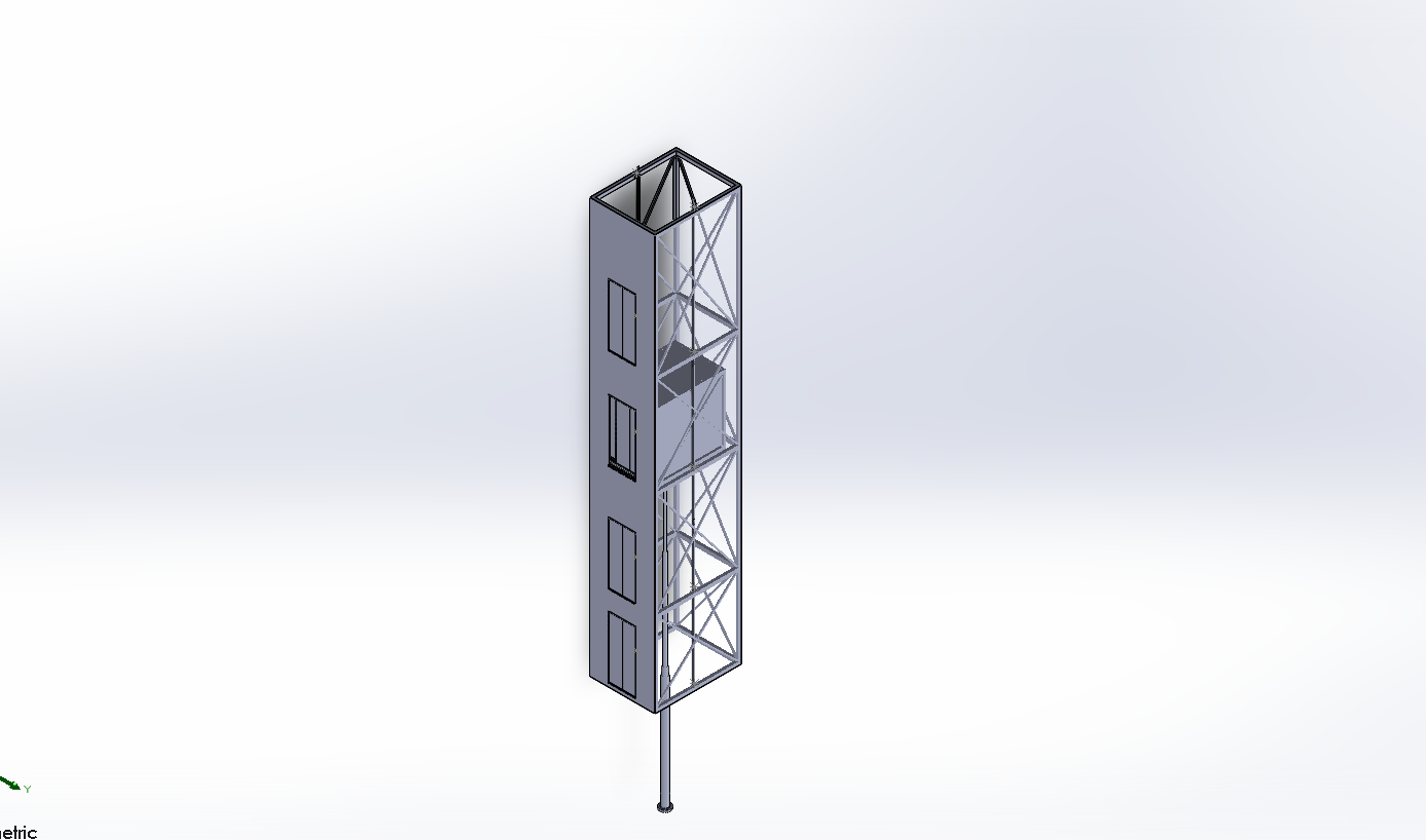
Rendered Elevator Design – Click to enlarge
WHY OPEN-SOURCE HYDRAULIC ELEVATOR DESIGN AND FEA
Open sourcing the hydraulic elevator design work is useful because future contributors need a clear record of the design process, assumptions, calculations, assembly sequence, finite element analysis setup, and remaining limitations. A hydraulic elevator assembly contains several interacting systems, and unclear assumptions can make the model difficult to replicate or improve.
This report is important because it documents how the elevator assembly was developed and checked. It explains why the shaft structure was redesigned, why guide rails and sliding guide shoes were selected, how the cab chassis was modified for load transfer, how major load cases were selected, how boundary conditions were applied, and what should be reviewed before future fabrication or construction.
The work also helps convert the SolidWorks model from a visual assembly into an engineering model with defined load paths. The redesigned shaft, cab chassis, guide rails, guide shoes, brackets, and hydraulic interface are all documented so that future contributors can understand how the system is intended to function.
Any design modification should be followed by a new safety assessment because changes to shaft member size, guide rail spacing, cab dimensions, hydraulic loading, guide shoe location, bracket layout, or connection type can change the stress and deformation behavior of the elevator assembly.
WAYS TO CONTRIBUTE AND RESEARCHERS
SUGGESTIONS | CONSULTING | MEMBERSHIP | OTHER OPTIONS
CLICK THESE ICONS TO JOIN US THROUGH SOCIAL MEDIA


RESEARCHERS FOR THIS COMPONENT:
HYDRAULIC ELEVATOR ENGINEERING DETAILS
This section documents the major design assumptions, subsystem layout, hand calculations, finite element analysis setup, assembly guide, physical assembly guidance, recommendations, resources, and frequently asked questions.
- What is open source hydraulic elevator design and FEA
- Why open-source hydraulic elevator design and FEA
- Key consultants
- Hydraulic elevator engineering details
- Basic Hydraulic Elevator Design Assumptions
- Material Properties
- Lift Shaft Design
- Elevator Cab Chassis Design
- Guide Rail Design
- Sliding Guide Shoe Design
- Guide Rail Bracket Design
- Hydraulic Rod-to-Cab Interface Design
- Hydraulic Connection Hand Check
- Enclosures, Doors, and Hydraulic Layout
- Finite Element Analysis
- SolidWorks Assembly Guide
- Physical Assembly Guide
- Final Elevator Design
- Final Design Summary
- Recommendations for Future Design Improvements
- Resources
- FAQ
- Final Note
BASIC HYDRAULIC ELEVATOR DESIGN ASSUMPTIONS
Multiple assumptions were required because the current project stage focused on CAD completion, structural sanity checking, and preliminary finite element analysis. The major assumptions are summarized here so future contributors can understand the basis of the model and update the report when new data becomes available.
The elevator is assumed to be a four-floor hydraulic elevator concept. The hydraulic jack is assumed to carry the primary vertical load. The guide rails are assumed to provide lateral guidance and alignment only. The guide rails are not treated as the primary vertical load-bearing structure.
The lift shaft is treated as a standalone structural frame. This means the shaft is checked as if it must support its own frame, guide rail brackets, enclosures, guide rail reactions, and overall alignment without relying on surrounding building walls for primary stability. The shaft was redesigned as a hollow braced steel frame to improve lateral stiffness and reduce the unsupported length of the vertical members.
The cab chassis is treated as the main structural frame of the elevator cab. The cab enclosure panels are not assumed to carry the primary hydraulic load. The hydraulic force is assumed to enter the cab through the hydraulic rod-to-cab interface and transfer into the bottom cab frame and vertical cab frame members.
Bolted joints were not modeled in detail. For the current finite element analysis, many connections were treated as bonded or welded. This was done to simplify the preliminary FEA setup. This assumption is acceptable for early stress and deformation checks, but it does not validate final bolted, welded, or clamped connection behavior.
The hydraulic system, door systems, and enclosure panels were modeled at the current layout and assembly-representation level. These components complete the SolidWorks assembly and support the final renderings, but they require additional design validation before fabrication or construction.
The key assumed dimensions and design values are shown below.
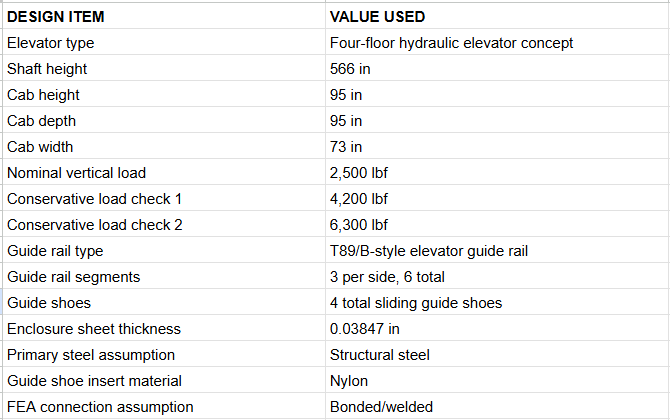
Elevator Design Dimension Assumptions – Click for source table
MATERIAL PROPERTIES
The following material properties were used for hand calculations and finite element analysis. These values should be replaced with supplier-provided material data as the design is developed further. The following are covered here:
- Structural Steel
- Guide Rail Steel
- Nylon Guide Shoe Insert
- Sheet Metal Enclosure Panels
STRUCTURAL STEEL
Structural steel was used for the shaft frame, cab chassis, guide rail brackets, guide shoe housing, hydraulic interface components, and other main structural steel members
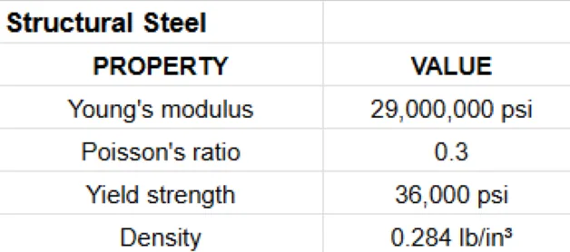
Structural Steel Material properties – Click for source table
GUIDE RAIL STEEL
The T89/B-style guide rails were modeled as steel. The same structural steel material properties were used for preliminary hand calculations and FEA unless supplier-specific guide rail data becomes available.
NYLON GUIDE SHOE INSERT
The sliding insert inside the guide shoe was modeled as nylon. Nylon was selected as a simple plastic liner material for the sliding interface between the steel guide rail and steel guide shoe housing.
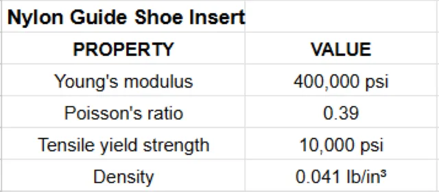
Nylon insert Material properties – Click for source table
The tensile yield strength was used as a preliminary comparison value for von Mises stress. Detailed nonlinear contact, creep, wear, lubrication, and friction behavior were not included.
SHEET METAL ENCLOSURE PANELS
The shaft and cab enclosure panels were modeled using steel sheet material with thickness of 0.03847 equivalent to 20-gauge steel sheets. These panels are included for enclosure and final assembly representation. They are not treated as the main structural members.
LIFT SHAFT DESIGN
The lift shaft was redesigned as a hollow braced steel frame. The purpose of the shaft is to support guide rail brackets, maintain guide rail alignment, provide the elevator travel envelope, support enclosure panels, and act as the fixed reference structure in the SolidWorks assembly.
This section discusses the following:
- The Shaft Dimensions
- The Shaft Loads
- Nominal Lateral Shaft Load
- Conservative Lateral Shaft Load
- Shaft Column Direct Compression
- Shaft Post Cross-Sectional Area
- Conservative Load per Shaft Post
- Shaft Post Direct Compression Stress
- Shaft Column Buckling Without Bracing
- Unbraced Shaft Post Euler Buckling
- Shaft Column Buckling With Bracing
- Braced Shaft Post Euler Buckling
- Shaft X-Bracing Member Properties
- X-Brace Cross-Sectional Area
- X-Brace Moment of Inertia
- X-Brace Radius of Gyration
- Calculated X-Brace Lengths
- Narrow-Face X-Brace Length
- Wide-Face X-Brace Length
- Calculated X-Brace Axial Force
- Narrow Face Brace Force – 500 lbf Lateral Load
- Wide Face Brace Force – 500 lbf Lateral Load
- Narrow Face Brace Force – 1,260 lbf Lateral Load
- Wide Face Brace Force – 1,260 lbf Lateral Load
- Maximum Checked X-Brace Axial Force
- X-Brace Axial Stress
- Maximum X-Brace Axial Stress
- X-Brace Buckling
- Narrow-Face X-Brace Buckling Capacity
- Wide-Face X-Brace Buckling Capacity
- X-Brace Buckling Factor of Safety
- Shaft Horizontal Ring Member
- Horizontal Ring Member Response – 500 lbf
- Horizontal Ring Member Response – 1,260 lbf
- Shaft Design Summary
The shaft redesign was needed because a tall frame can appear strong in direct compression but still perform poorly in lateral sway, racking, and guide rail alignment. The shaft is 566 in tall, so bracing is important to reduce unsupported column length and improve global stiffness.
The redesigned shaft uses main vertical posts, horizontal ring members, and X-bracing on the major sides. The bracing provides a lateral load path and helps prevent the rectangular shaft from racking under guide loads or assembly loads.
The assumed shaft structural members used for the calculations are:

Table depicting structural members used for calculations and design – Click for source table
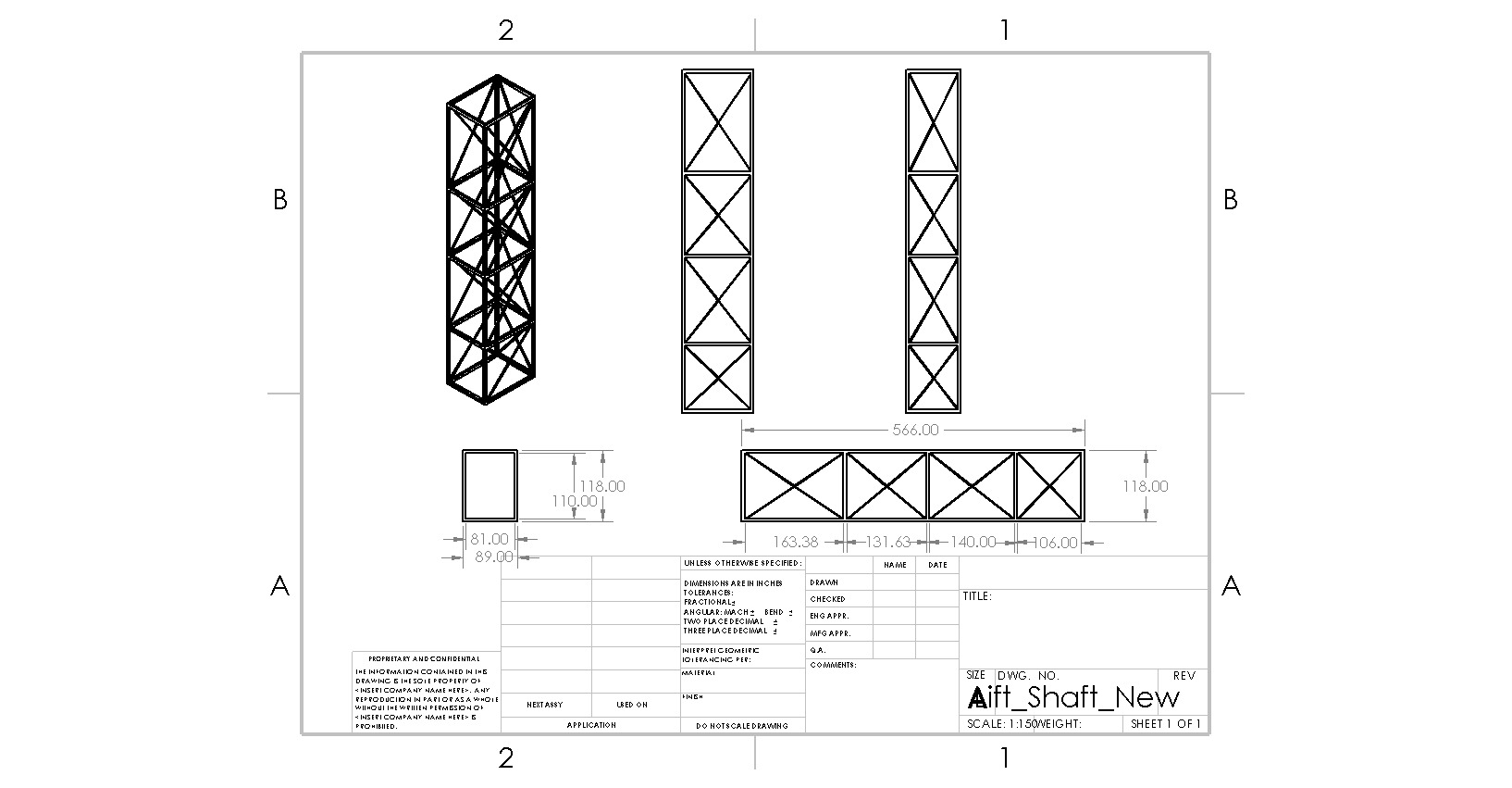
Representative image of the elevator shaft – Click to enlarge
THE SHAFT DIMENSIONS
This section establishes the basic size of the elevator shaft and the height of each braced section. These dimensions are needed because the length and width of the frame directly affect how much the steel members can bend or buckle. The same dimensions are used throughout the shaft calculations that follow.
The bay height used for bracing calculations is 111 in. This corresponds to dividing the shaft height into multiple braced levels. The exact bay height should be updated if the final SolidWorks model uses different bracing levels.

Table depicting dimensions of structural members used for calculations and design – Click for source table
THE SHAFT LOADS
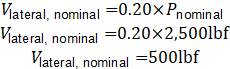
The shaft load cases are defined before the structural checks so that every later calculation uses the same design basis. The main vertical reference load is 2,500 lbf, while 4,200 lbf and 6,300 lbf are retained as higher preliminary checks. Because the hydraulic jack is assumed to carry the primary vertical load, the shaft calculations use an assumed portion of the vertical load as a lateral force to represent preliminary sideways demand on the braced frame.
For these checks, P represents the selected vertical elevator load and V_lateral represents the corresponding lateral shaft load. A lateral-load factor of 0.20, or 20%, is used as a preliminary sanity-check assumption. The nominal lateral case is therefore based on P_nominal = 2,500 lbf, and the conservative lateral case is based on P_conservative = 6,300 lbf. These are preliminary design loads rather than final code-defined elevator load combinations.
NOMINAL LATERAL SHAFT LOAD
The nominal lateral shaft load represents the preliminary sideways force used for the normal design case. It is calculated as 20% of the 2,500 lbf nominal vertical elevator load. In the equation below, V_lateral,nominal is the assumed nominal lateral force, P_nominal is the 2,500 lbf reference vertical load, and 0.20 is the selected lateral-load factor. The resulting 500 lbf value is used in the nominal brace-force and horizontal-member checks.
CONSERVATIVE LATERAL SHAFT LOAD
The conservative lateral shaft load applies the same 20% lateral-load assumption to the higher 6,300 lbf vertical load. Here, V_lateral,conservative is the assumed conservative sideways force and P_conservative is the 6,300 lbf vertical reference load. The resulting 1,260 lbf lateral force provides the more demanding preliminary case for the shaft bracing and horizontal ring-member calculations.
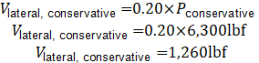
These loads are not final code-defined elevator loads. They are preliminary lateral checks used to evaluate whether the braced shaft layout is reasonable
SHAFT COLUMN DIRECT COMPRESSION
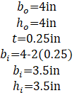
The first shaft-post strength check evaluates direct compression in the four main HSS 4 x 4 x 0.25 vertical posts. Direct compression describes the squeezing stress produced when the vertical elevator load is carried through the steel cross-section. The calculation first determines the amount of steel in one hollow post, then assigns one-quarter of the conservative vertical load to each post, and finally divides that load by the steel area to obtain compressive stress.
SHAFT POST CROSS-SECTIONAL AREA
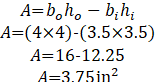
The shaft-post cross-sectional area, A, is the amount of steel available to carry axial load. Because the HSS member is hollow, the inner empty area must be subtracted from the outside square. In the geometry below, bo and ho are the 4 in outside width and height, t is the 0.25 in wall thickness used in this simplified calculation, and bi and hi are the resulting 3.5 in inside dimensions. The calculated area is then used in the direct-compression stress check.
CONSERVATIVE LOAD PER SHAFT POST
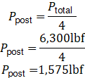
The conservative load per shaft post, P_post, is found by distributing the 6,300 lbf total conservative vertical load equally among the four primary shaft posts. P_total represents the total applied vertical load and the divisor of four represents the four assumed load-carrying posts. The resulting 1,575 lbf per post is the axial force used in the direct-compression calculation.
SHAFT POST DIRECT COMPRESSION STRESS
The direct compressive stress, sigma, indicates how much axial force is carried by each square inch of steel in one shaft post. It is calculated using sigma = P/A, where P is the 1,575 lbf conservative load assigned to one post and A is the calculated 3.75 in2 steel cross-sectional area. The resulting stress is compared with the assumed 36,000 psi steel yield strength to determine whether simple material compression is a controlling condition.
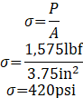
The calculated direct compression stress is much lower than the assumed steel yield strength of 36,000 psi. This means direct compression is not the main concern. The shaft design is more likely controlled by lateral sway, buckling length, racking, guide rail alignment, and connection behavior.
SHAFT COLUMN BUCKLING WITHOUT BRACING
Direct compressive stress alone does not describe the stability of a tall shaft post. A long member can become unstable and bow sideways, or buckle, before the steel reaches its material yield strength. A preliminary Euler column-buckling check is therefore performed using the approximately full unsupported shaft-post length to establish a reference unbraced condition.
For the HSS 4 × 4 × 0.25 inshaft post:
UNBRACED SHAFT POST EULER BUCKLING
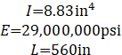
The critical buckling load, Pcr, is the estimated compressive force at which an ideal straight column can lose stability and begin to bow sideways. The Euler relation used here depends on E, the elastic modulus of steel; I, the second moment of area of the HSS cross-section; and L, the unsupported column length. For the HSS 4 x 4 x 0.25 post, E = 29,000,000 psi, I = 8.83 in4, and the unbraced reference length is L = 560 in. The result provides a simplified baseline for comparison with the braced shaft.
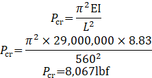
The unbraced buckling capacity is not low compared with the load per post, but it is not a good design basis for a tall elevator shaft because it does not account for lateral sway, guide rail alignment, eccentricity, frame racking, base flexibility, or connection behavior. This supports the decision to add bracing and reduce unsupported length.
SHAFT COLUMN BUCKLING WITH BRACING
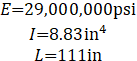
The buckling calculation is repeated after the shaft is divided into shorter unsupported segments by the horizontal framing and X-bracing. Because Euler buckling capacity varies inversely with the square of unsupported length, reducing the effective length can greatly increase column stability. The braced calculation uses the same steel stiffness and post section properties but reduces the unsupported length to 111 in, representing one braced shaft bay.
BRACED SHAFT POST EULER BUCKLING
For the braced condition, Pcr again represents the estimated critical buckling load, E is the 29,000,000 psi elastic modulus, I is the 8.83 in4 second moment of area, and L is reduced to 111 in. Substituting the shorter unsupported length into the same Euler relation quantifies the increase in idealized buckling resistance created by the intermediate shaft bracing.
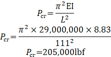
The braced condition provides much higher estimated buckling resistance than the unbraced condition. This demonstrates why the shaft redesign uses horizontal frame levels and X-bracing. The bracing reduces unsupported length and improves global stiffness.
SHAFT X-BRACING MEMBER PROPERTIES
The X-braces provide a diagonal load path that limits shaft racking and lateral sway. Before the braces can be checked for axial stress and compression buckling, the basic section properties of the selected HSS 2 x 2 x 0.1875 member are established. The calculations determine the steel area A, the second moment of area I, and the radius of gyration r, which describe the member’s axial load-carrying area and resistance to instability.
X-BRACE CROSS-SECTIONAL AREA
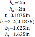
The brace cross-sectional area, A, is the amount of steel available to carry tension or compression along the diagonal member. The area is calculated by subtracting the hollow inner square from the outside square. In the geometry below, bo and ho are the 2 in outside dimensions, t is the 0.1875 in wall thickness used in the simplified section calculation, and bi and hi are the resulting 1.625 in inside dimensions.
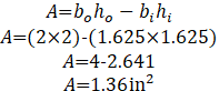
X-BRACE MOMENT OF INERTIA
The second moment of area, I, describes how the brace cross-section resists bending about its centroidal axis. This property is important for compression stability because a section with greater bending stiffness is more resistant to buckling. The rectangular-tube expression below uses the outside dimensions bo and ho and the hollow inside dimensions bi and hi to obtain I for the selected HSS brace.
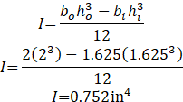
X-BRACE RADIUS OF GYRATION
The radius of gyration, r, combines the brace area and second moment of area into a single geometric measure used in column-slenderness and buckling evaluations. It is calculated from r = sqrt(I/A), where I is the calculated 0.752 in4 second moment of area and A is the 1.36 in2 steel cross-sectional area. The result describes how the brace material is distributed around the member centerline.
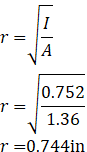
CALCULATED X-BRACE LENGTHS
The actual diagonal length of each X-brace is required because brace geometry affects both the axial force developed under lateral loading and the member’s buckling capacity. Each brace forms the hypotenuse of a right triangle made by the 111 in braced-bay height and the width of the corresponding shaft face. The diagonal length d is therefore calculated from the bay height h and face width b using the Pythagorean relationship shown below.

NARROW-FACE X-BRACE LENGTH
For the narrow shaft face, h is the 111 in braced-bay height and b is the 89 in shaft-face width. The calculated diagonal length d represents the unsupported length of the narrow-face brace used later in both the brace-force geometry and compression-buckling checks.
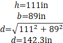
WIDE-FACE X-BRACE LENGTH
For the wide shaft face, h remains 111 in while b increases to 118 in. The resulting diagonal length d is longer than the narrow-face brace, which affects the brace angle and reduces the ideal Euler buckling capacity because buckling resistance decreases as unsupported length increases.
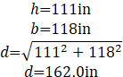
These brace lengths are used in the axial force and buckling checks.
CALCULATED X-BRACE AXIAL FORCE
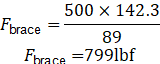
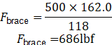
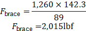
When a lateral shear V acts on a braced shaft bay, the diagonal member resists that sideways motion through an axial force along its own length. For this conservative preliminary check, one diagonal is assumed to carry the full bay shear. The brace force F_brace is obtained from the lateral shear V, the diagonal length d, and the shaft-face width b using F_brace = Vd/b. The equation accounts for the fact that the diagonal member is inclined rather than horizontal.

NARROW FACE BRACE FORCE – 500 LBF LATERAL LOAD
This case evaluates the narrow 89 in shaft face under the 500 lbf nominal lateral shear. In the equation, V = 500 lbf is the applied bay shear, d = 142.3 in is the narrow-face diagonal length, and b = 89 in is the horizontal shaft-face width. The result is the axial force carried by one diagonal under the nominal narrow-face condition.
WIDE FACE BRACE FORCE – 500 LBF LATERAL LOAD
This case applies the same 500 lbf nominal lateral shear to the 118 in wide shaft face. Here, d = 162.0 in and b = 118 in. Because the brace angle differs from the narrow face, the resulting axial force is calculated separately even though the applied lateral shear is unchanged.
NARROW FACE BRACE FORCE – 1,260 LBF LATERAL LOAD
This case evaluates the narrow 89 in face under the higher 1,260 lbf conservative lateral shear. The same diagonal geometry is used, with d = 142.3 in and b = 89 in. This combination produces the largest brace demand among the four checked geometry and load cases and is therefore carried forward to the stress and factor-of-safety checks.
WIDE FACE BRACE FORCE – 1,260 LBF LATERAL LOAD
This case applies the 1,260 lbf conservative lateral shear to the 118 in wide shaft face. The brace force is calculated using d = 162.0 in and b = 118 in so the effect of the wider bay geometry can be compared directly with the narrow-face conservative case.
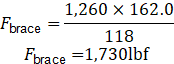
MAXIMUM CHECKED X-BRACE AXIAL FORCE
The maximum checked brace force, F_brace,max, is the largest axial demand obtained from the four brace-load cases. Selecting the highest value provides a conservative single force for the subsequent direct-stress and buckling factor-of-safety calculations. The governing value from the current calculations is 2,015 lbf.

X-BRACE AXIAL STRESS
This calculation checks how intensely the selected X-brace is being pulled or compressed internally. It divides the force in the brace by the amount of steel in the tube. The result is compared with the steel strength to see whether the brace material is being overloaded.
The brace axial stress is calculated by dividing the axial force by the brace cross-sectional area.

MAXIMUM X-BRACE AXIAL STRESS
This calculation applies the largest previously calculated brace force to the brace cross-section. It gives the highest direct stress expected in the selected brace for the checked cases. The result provides a simple strength check before considering buckling.
This calculation divides the maximum brace axial force by the HSS brace area to obtain normal stress. The result is compared with the assumed 36,000 psi steel yield strength as a preliminary yielding check.
Using the highest checked brace axial force:
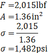
The calculated axial stress is much lower than the assumed steel yield strength of 36,000 psi. This indicates that the brace has adequate preliminary axial stress capacity for the checked lateral load cases.
X-BRACE BUCKLING
A diagonal brace can carry tension for one direction of lateral loading and compression when the loading direction reverses. Compression introduces the possibility of elastic buckling, so both calculated brace lengths are checked using the same simplified Euler column relationship. The critical load Pcr is compared with the maximum brace demand to evaluate preliminary stability rather than material yielding alone.

NARROW-FACE X-BRACE BUCKLING CAPACITY
The narrow-face brace buckling calculation uses Pcr = pi^2EI/L^2, where E = 29,000,000 psi is the steel elastic modulus, I = 0.752 in4 is the brace second moment of area, and L = 142.3 in is the narrow-face diagonal length. Pcr represents the idealized compression load at which this brace could lose stability and bow sideways.
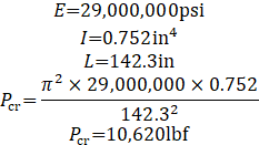
WIDE-FACE X-BRACE BUCKLING CAPACITY
The wide-face brace is checked with the same steel modulus and section stiffness but with the longer L = 162.0 in diagonal length. Because the Euler buckling load decreases with the square of member length, this longer brace is expected to have the lower critical buckling capacity and therefore provides the more restrictive preliminary stability case.
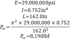
The lowest estimated Euler buckling capacity is:

The maximum checked brace axial force is:

X-BRACE BUCKLING FACTOR OF SAFETY
The buckling factor of safety, FS, compares the lowest calculated brace buckling capacity with the highest calculated brace axial demand. Pcr,min is the lower of the two Euler buckling capacities, and F_brace,max is the 2,015 lbf governing brace force. The ratio FS = Pcr,min/F_brace,max indicates how many times larger the simplified predicted buckling load is than the applied preliminary brace load.
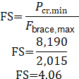
The preliminary buckling factor of safety is 4.06 for the checked conservative lateral case. This supports the use of HSS 2 x 2 x 0.1875 bracing for the current shaft concept, assuming the final CAD uses the same member size and similar braced lengths.
SHAFT HORIZONTAL RING MEMBER
The horizontal ring members connect the main shaft posts, support the X-bracing, and provide structural locations for guide-rail brackets. Hand calculations use simplified Euler-Bernoulli beam theory to evaluate two primary checks under lateral loading: bending stress, which indicates member strength, and mid-span deflection, which indicates stiffness and potential guide-alignment movement. A representative HSS 4 x 4 x 0.25 member is checked over the conservative 118 in the shaft-face span.

member properties:
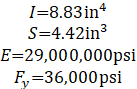
A conservative span of 118 in was used.

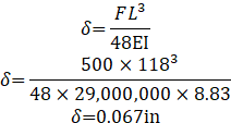
HORIZONTAL RING MEMBER RESPONSE – 500 LBF
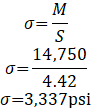
The nominal ring-member case treats the 118 in horizontal HSS member as a simply supported beam with a 500 lbf point load applied at mid-span. F is the applied lateral load, L is the 118 in span, M is the maximum bending moment, S = 4.42 in3 is the section modulus used to calculate bending stress, E = 29,000,000 psi is the steel elastic modulus, and I = 8.83 in4 is the second moment of area used to calculate deflection. The standard center-point-load relationships are applied below.
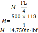
The bending stress is calculated by dividing the bending moment by the section modulus.
The deflection is calculated using the simply supported beam equation for a center point load.
HORIZONTAL RING MEMBER RESPONSE – 1,260 LBF
The conservative ring-member check repeats the same simply supported center-load model using F = 1,260 lbf while keeping the 118 in span and the same HSS section properties. This case shows how the bending moment, bending stress, and mid-span deflection increase as the lateral demand rises. The calculated stress is compared with the 36,000 psi assumed yield strength, while the deflection is reviewed for its potential effect on guide-rail alignment.
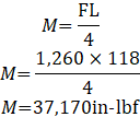
The bending stress is:
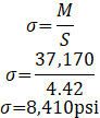
The deflection is:
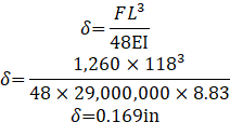
The calculated stresses are below the assumed steel yield strength. The deformation should still be reviewed in the full shaft FEA because guide rail alignment may be more sensitive to deflection than to stress.
SHAFT DESIGN SUMMARY
The shaft redesign is supported by the preliminary calculations. Direct compression stress in the main shaft posts is low. The bracing significantly reduces effective unsupported length and increases estimated column buckling capacity. The HSS 2 x 2 x 0.1875 X-bracing shows low axial stress and acceptable preliminary buckling capacity for the checked lateral load cases. The HSS 4 x 4 x 0.25 horizontal ring member also shows acceptable preliminary bending stress for the representative lateral load checks.
The shaft should still be reviewed through FEA because a real shaft frame depends on joint behavior, base anchorage, lateral sway, guide rail bracket loads, connection stiffness, and fabrication tolerances.
ELEVATOR CAB CHASSIS DESIGN
The elevator cab chassis was redesigned to provide a clear hydraulic load path and guide shoe mounting structure. The cab is not treated as a simple box made from enclosure panels. Instead, the cab chassis is treated as the main structural frame that carries the hydraulic load and supports the guide shoe brackets.
This section discusses the following:
- The Cab Hydraulic Load
- Cab Bottom Hydraulic Load Beams
- Load per Cab Hydraulic Beam
- Required Hydraulic Beam Section Modulus
- Selected HSS Beam Stress and Deflection
- Cab Load-Transfer Plate
- Local Hydraulic Plate Bearing Pressure
- Load-Transfer Plate Section Properties and Clear Span
- Load-Transfer Plate Bending – 2,500 lbf
- Load-Transfer Plate Bending – 6,300 lbf
- Vertical Cab Frame Members
- Vertical Cab Member Section Properties
- Vertical Cab Member Direct Compression
- Vertical Cab Member Buckling
- Guide Shoe Bracket Moment into Cab Frame
- Guide Shoe Bracket Moment
- Cab Frame Bending Stress from Guide Shoe Bracket
- Cab Chassis Design Summary
The assumed cab dimensions are:

Table depicting elevator cab chassis dimensions – Click for source table
The main cab structural members used in the design discussion are:
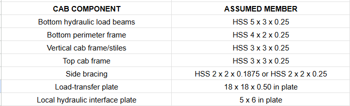
Table depicting elevator cab chassis structural members – Click for source table
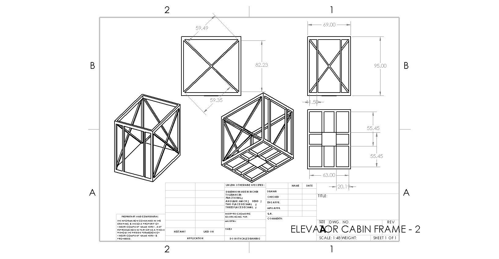
Image of the elevator cab – Click to enlarge
THE CAB HYDRAULIC LOAD
The nominal hydraulic load used for cab chassis calculations is 2,500 lbf. Conservative checks were also considered at 4,200 lbf and 6,300 lbf.
P = 2,500 lbf
The hydraulic force is assumed to enter the cab through the hydraulic interface at the cab bottom and then transfer into the cab chassis.
CAB BOTTOM HYDRAULIC LOAD BEAMS
The two primary bottom HSS beams carry the hydraulic lifting force from the central load-transfer region into the cab chassis. The beam checks use a simplified, simply supported model to evaluate load sharing, required bending strength, actual bending stress, and center deflection. The nominal 2,500 lbf hydraulic force is assumed to be shared equally between the two beams over the 73 in cab width.
LOAD PER CAB HYDRAULIC BEAM
The load carried by one hydraulic beam, P_beam, is obtained by dividing the total nominal hydraulic load P_total equally between the two primary bottom beams. With P_total = 2,500 lbf, each beam is assigned 1,250 lbf for the simplified bending and deflection calculations. The beam span L is taken as the 73 in cab width.
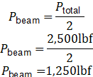
The cab width is 73 in, so the hydraulic load beams were checked using a 73 in span.
L = 73in
The maximum bending moment is calculated using the simply supported beam equation for a center point load.
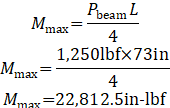
REQUIRED HYDRAULIC BEAM SECTION MODULUS
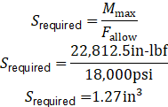
The required section modulus, S_required, is calculated to estimate the minimum bending capacity a candidate cab beam should provide before a specific HSS size is selected. M_max is the maximum bending moment from the 1,250 lbf center-load beam model, and F_allow = 18,000 psi is the preliminary allowable bending stress used in this sizing check. Dividing M_max by F_allow gives the minimum section modulus used to compare the candidate HSS members.
The compared member options are shown below.

Elevator load bearing members comparison – Click for source table
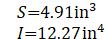
For HSS 5 x 3 x 0.25 :
SELECTED HSS BEAM STRESS AND DEFLECTION
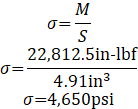
The selected HSS 5 x 3 x 0.25 beam is then checked directly for both strength and stiffness. Bending stress is calculated from sigma = M/S using M = 22,812.5 in-lbf and the selected section modulus S = 4.91 in3. Mid-span deflection is calculated using the simply supported center-point-load relation, where P_beam = 1,250 lbf, L = 73 in, E = 29,000,000 psi, and I = 12.27 in4. These results show whether the chosen beam remains both strong and reasonably stiff under the nominal shared hydraulic load.
The beam deflection is calculated using the simply supported beam equation for a center point load.

Using:
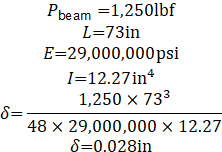
The HSS 5 x 3 x 0.25 beam gives low stress and low deflection for the nominal hydraulic load. It was selected as the preferred preliminary hydraulic load beam, with the 5 in dimension oriented vertically.
CAB LOAD-TRANSFER PLATE
The hydraulic force enters the cab through a relatively small local connection, so a larger 18 x 18 x 0.50 in steel plate is used to spread that concentrated force into the two primary bottom beams. The plate calculations first check average local bearing pressure at the 5 x 6 in interface and then use a simplified beam-strip model to evaluate bending of the larger transfer plate between the supporting beams.

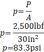
LOCAL HYDRAULIC PLATE BEARING PRESSURE
The average bearing pressure, p, represents the nominal hydraulic force distributed over the local 5 x 6 in contact area. P is the 2,500 lbf nominal hydraulic load and A is the 30 in2 local interface area. The relation p = P/A provides a simple average contact-pressure check before the larger plate is evaluated for bending.
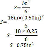
LOAD-TRANSFER PLATE SECTION PROPERTIES AND CLEAR SPAN
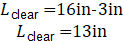
The simplified plate-bending model requires both a section modulus and an unsupported span. The section modulus S is calculated for an 18 in wide, 0.50 in thick rectangular plate strip using S = bt^2/6, where b is the effective strip width and t is the plate thickness. The clear span L_clear is estimated from the 16 in beam center-to-center spacing minus the 3 in beam width, giving the unsupported plate distance used in the bending checks.
Using a 16 in center-to-center beam spacing and 3 in beam width, the clear unsupported span is estimated as:
LOAD-TRANSFER PLATE BENDING – 2,500 LBF
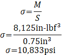
The nominal plate-bending check treats the load-transfer plate as a simplified beam strip spanning the 13 in clear distance between the two hydraulic load beams. P = 2,500 lbf is applied as the nominal center load, M is the resulting maximum bending moment, and sigma = M/S converts that moment into bending stress using the previously calculated plate section modulus S = 0.75 in3. The result is compared with the assumed steel yield strength as a preliminary strength check.
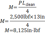
The bending stress in the load-transfer plate is:
LOAD-TRANSFER PLATE BENDING – 6,300 LBF
The conservative plate-bending check repeats the same simplified 13 in span model using P = 6,300 lbf. The geometry and section modulus remain unchanged, so the larger load directly increases the bending moment and plate stress. This higher case indicates how much strength margin remains before detailed plate, connection, and local-contact analysis is completed.
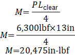
The bending stress is:
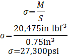
The plate stress remains below the assumed steel yield strength for this simplified bending check. The larger load-transfer plate is justified because it spreads the hydraulic load into the two main beams and reduces the risk of local plate bending.
VERTICAL CAB FRAME MEMBERS
The vertical HSS 3 x 3 x 0.25 cab members form the primary upright frame and also support the guide-shoe mounting regions. Their preliminary checks establish the section properties and then evaluate direct compression and Euler buckling. These calculations determine whether simple axial loading or column instability is likely to control the selected vertical member before local guide-shoe and connection effects are considered.
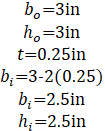
For HSS 3 x 3 x 0.25 :
VERTICAL CAB MEMBER SECTION PROPERTIES
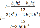
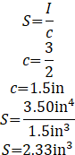
The cab-upright section properties describe how much steel is available to carry axial load and how resistant the tube is to bending and buckling. A is the cross-sectional steel area, I is the second moment of inertia, and S is the section modulus. The simplified HSS geometry uses 3 in outside dimensions, 0.25 in wall thickness, and 2.5 in inside dimensions. The section modulus is obtained from S = I/c, where c is the 1.5 in distance from the neutral axis to the outside surface.
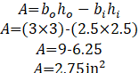
The moment of inertia is calculated using the rectangular tube equation.
The section modulus is calculated by dividing moment of inertia by the distance from the neutral axis to the outer surface.
VERTICAL CAB MEMBER DIRECT COMPRESSION
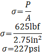
The direct-compression check assumes the 2,500 lbf nominal cab load is shared equally by four vertical frame members. P_stile is therefore the load carried by one upright, and A = 2.75 in2 is the calculated steel area of the HSS 3 x 3 x 0.25 section. The compressive stress sigma is calculated from P/A and compared with the assumed steel yield strength to determine whether simple axial compression is significant.
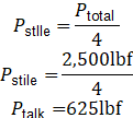
The direct compression stress is calculated by dividing the load per stile by the cross-sectional area.
VERTICAL CAB MEMBER BUCKLING
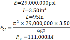
The cab upright is also checked for ideal elastic buckling because a vertical member can lose stability before reaching the material yield stress. Pcr is the critical buckling load calculated using the Euler relationship, with E = 29,000,000 psi, I = 3.50 in4, and L = 95 in representing the cab-member height used as the effective unsupported length in this preliminary model.

Using:
The direct compression stress is very low compared with the assumed steel yield strength of 36,000 psi. The vertical cab frame members are more likely to be controlled by guide shoe bracket loads, local connection behavior, and frame racking than by direct compression.
GUIDE SHOE BRACKET MOMENT INTO CAB FRAME
The guide shoe is offset from the main cab frame, so a lateral guide force produces both a direct force and a bending moment at the cab attachment. The simplified check evaluates the moment created by the 5 in stand-off distance and then converts that moment into bending stress in the supporting HSS 3 x 3 x 0.25 cab member. Reducing the offset reduces the bending demand transferred into the frame.
GUIDE SHOE BRACKET MOMENT
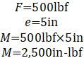
The bracket moment, M, is calculated from M = Fe, where F is the lateral guide-shoe force and e is the perpendicular offset between the guide load and the cab frame. For the conservative local check, F = 500 lbf and e = 5 in. The resulting bending moment represents the rotational demand transferred from the offset guide shoe into the cab structural member.
M = Fe
Using a conservative guide shoe load of 500 lbf and a 5 in offset:
If this moment is transferred into an HSS cab frame member:

CAB FRAME BENDING STRESS FROM GUIDE SHOE BRACKET
The bending stress in the cab frame is calculated from sigma = M/S. M is the 2,500 in-lbf guide-shoe bracket moment and S = 2.33 in3 is the section modulus of the HSS 3 x 3 x 0.25 cab member. The resulting stress is compared with the assumed 36,000 psi steel yield strength to determine whether the offset guide-shoe load creates a significant local bending demand in the frame.
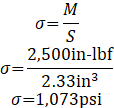
The calculated stress is low compared with the assumed steel yield strength of 36,000 psi. This supports attaching the guide shoe brackets to the cab structural frame, as long as the bracket load is transferred into the HSS frame members and not only into thin enclosure panels.
CAB CHASSIS DESIGN SUMMARY
The cab chassis redesign is supported by the preliminary calculations. The HSS 5 x 3 x 0.25 bottom hydraulic load beams provide low stress and low deflection for the 2,500 lbf load case. The 18 x 18 x 0.50 in load-transfer plate helps spread the hydraulic load into the two main beams. The HSS 3 x 3 x 0.25 vertical cab frame members show low direct compression stress and high preliminary buckling capacity. The reduced 5 in guide shoe offset keeps guide shoe bracket moment manageable.
GUIDE RAIL DESIGN
The guide rail system uses a T89/B-style elevator guide rail profile. The guide rails are intended to provide lateral cab guidance and alignment. They are not treated as the main vertical load-carrying system.
This section discusses the following:
- Guide Rail Lateral Loads
- Normal Lateral Guide Load
- Higher Lateral Guide Load
- Guide Load Distribution per Shoe
- Guide Rail Section Properties
- Guide Rail Bending and Deflection
- Guide Rail Bending and Deflection Equations
- Guide Rail Check – 60 in Bracket Spacing
- Guide Rail Check – 80 in Bracket Spacing
- Guide Rail Check – 96 in Bracket Spacing
- Guide Rail Factor of Safety – 96 in Spacing
- Guide Rail Design Summary
The guide rail dimensions used in the model are shown below.
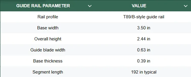
Guide Rail dimensions – Click for source table
The rail segmentation is:
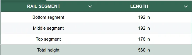
Guide Rail segmentation – Click for source table
Each side uses three rail segments. Two sides use six rail segments total.
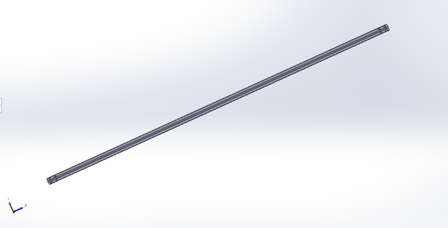
Guide Rail – Click to enlarge


VIDEO COMING: HOW TO ASSEMBLE THE GUIDE RAILS
SEE OUR HOW TO HELP AND/OR CROWDFUNDING CAMPAIGN PAGE TO HELP CREATE ALL THE TUTORIAL VIDEOS FASTER
GUIDE RAIL LATERAL LOADS
The guide rails are treated as lateral guidance members rather than as the primary vertical lifting structure. Preliminary guide loads are therefore derived as percentages of the 2,500 lbf nominal elevator load and are then distributed among the four guide shoes. F_lat denotes the total assumed lateral guide load, while F_shoe denotes the corresponding load assigned to one guide shoe for local rail and shoe checks.
NORMAL LATERAL GUIDE LOAD
The normal guide-load case assumes the lateral force is 10% of the 2,500 lbf nominal elevator load. In the equation below, F_lat is the total lateral guide force and the factor 0.10 represents the selected normal-load percentage. The resulting 250 lbf total lateral load is used as the lower preliminary guide-system case.
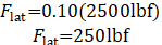
HIGHER LATERAL GUIDE LOAD
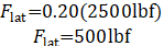
The higher guide-load case increases the assumed lateral demand to 20% of the same 2,500 lbf nominal elevator load. F_lat again represents the total lateral guide force, while 0.20 is the higher preliminary load factor. The resulting 500 lbf case is used for the more demanding guide-rail and guide-shoe evaluations.
GUIDE LOAD DISTRIBUTION PER SHOE
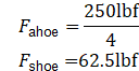
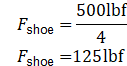
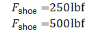
The total lateral guide force is divided among the four sliding guide shoes to estimate a nominal reaction at one shoe. F_shoe represents the load carried by one guide shoe and F_lat is the total lateral guide force, so the basic distribution uses F_shoe = F_lat/4. This gives 62.5 lbf per shoe for the 250 lbf total case and 125 lbf per shoe for the 500 lbf total case. Additional local checks at 250 lbf and 500 lbf per shoe are retained as higher preliminary contact cases.

For a total lateral load of 250 lbf
For a total lateral load of 500 lbf
Additional local guide-shoe checks:
Guide Rail Section Properties
Additional local checks were considered at 250 lbf and 500 lbf per guide shoe.
GUIDE RAIL SECTION PROPERTIES
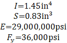
The T89/B-style guide rail was a T-section for preliminary calculations.
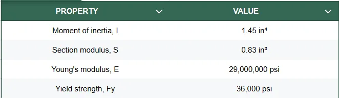
Guide Rail section properties – Click for source table
GUIDE RAIL BENDING AND DEFLECTION
The guide rail is checked as a simplified simply supported beam spanning between guide-rail brackets and carrying a lateral point load at mid-span. This model is used to evaluate both bending stress and lateral deflection because guide-rail performance can be governed by alignment and stiffness even when the material stress remains below yield. Several bracket spacings are compared using the same 500 lbf lateral load.
GUIDE RAIL BENDING AND DEFLECTION EQUATIONS
The beam equations below are used consistently for each bracket-spacing case. F is the applied center lateral load, L is the distance between guide-rail supports, M_max is the maximum bending moment, S is the rail section modulus, sigma is the maximum bending stress, E is the steel elastic modulus, I is the rail second moment of area, and delta is the maximum center deflection. For a simply supported beam with a center point load, the standard relationships are M_max = FL/4, sigma = M/S, and delta = FL^3/(48EI).

Bending stress:

Maximum center deflection:

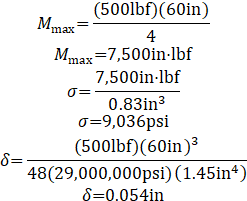
GUIDE RAIL CHECK – 60 IN BRACKET SPACING
The first guide-rail case uses F = 500 lbf and a support spacing L = 60 in. The same rail properties, S = 0.83 in3, I = 1.45 in4, and E = 29,000,000 psi, are used to calculate maximum bending moment, bending stress, and center deflection. This shortest spacing provides the baseline for comparing how increasing the unsupported rail length affects the guide system.
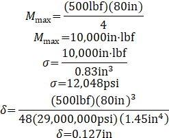
GUIDE RAIL CHECK – 80 IN BRACKET SPACING
The second guide-rail case increases the bracket spacing to L = 80 in while keeping the same 500 lbf center lateral load and rail properties. Because the bending moment grows with span and deflection grows strongly with the cube of span in this loading model, this case demonstrates the increased stress and movement produced by a wider support spacing.
GUIDE RAIL CHECK – 96 IN BRACKET SPACING
The third guide-rail case uses the widest checked support spacing, L = 96 in, with the same 500 lbf center lateral load. This is the most demanding of the three spacing cases because the longer unsupported rail segment produces the highest calculated bending moment, stress, and deflection. The result is used for the preliminary rail factor-of-safety check.
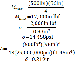
GUIDE RAIL FACTOR OF SAFETY – 96 IN SPACING
The guide-rail factor of safety, FS, compares the assumed steel yield strength with the maximum bending stress from the 96 in the spacing case. Fy = 36,000 psi is the assumed rail-steel yield strength and sigma_max = 14,458 psi is the calculated maximum bending stress. The ratio FS = Fy/sigma_max provides a preliminary strength margin, while the separate deflection result must still be reviewed for alignment and serviceability.
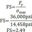
The stress values remain below the assumed steel yield strength for the checked cases. However, deflection increases significantly as bracket spacing increases. Based on this check, 60-80 in guide rail bracket spacing is preferred.
GUIDE RAIL DESIGN SUMMARY
The T89/B-style guide rail is reasonable for the preliminary elevator model. The rail stress is acceptable for the checked lateral guide load cases, but rail deflection and cab alignment are important. Bracket spacing should preferably remain in the 60-80 in range unless future FEA and supplier data support larger spacing.
SLIDING GUIDE SHOE DESIGN
The elevator cab uses four sliding guide shoes. Each guide shoe interfaces with the T89/B-style guide rail blade. The guide shoes are mounted to the cab frame and provide lateral cab alignment during travel.
This section discusses the following:
- Guide Shoe Contact Area
- Guide Shoe Contact Area Calculation
- Guide Shoe Contact Pressure
- Guide Shoe Contact Pressure – 125 lbf
- Guide Shoe Contact Pressure – 250 lbf
- Guide Shoe Contact Pressure – 500 lbf
- Guide Shoe FEA Boundary Conditions
- Guide Shoe Design Summary
The guide shoe assembly consists of:
- Steel guide shoe housing
- Nylon sliding insert
- U-shaped groove
- Cab-side mounting face
- Guide rail contact surfaces
The guide shoe is not intended to carry the main vertical elevator load. Its purpose is lateral guidance.
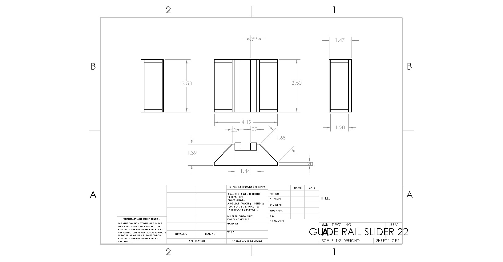
Guide Rail Slider – Click to enlarge
VIDEO COMING: HOW TO INSTALL GUIDE RAIL SLIDERS
SEE OUR HOW TO HELP AND/OR CROWDFUNDING CAMPAIGN PAGE TO HELP CREATE ALL THE TUTORIAL VIDEOS FASTER
UIDE SHOE CONTACT AREA
The sliding guide shoe keeps the cab centered by contacting the narrow blade of the guide rail through a nylon liner. This calculation determines the size of the surface over which that sideways force is spread. The contact area is needed to estimate the pressure on the nylon insert.
The guide shoe contact pressure was checked using the contact area between the guide rail blade and nylon liner.
Assumed contact height:
h = 5in
Guide rail blade width:
b = 0.63in
GUIDE SHOE CONTACT AREA CALCULATION
This calculation multiplies the assumed contact height by the guide-rail blade width to estimate the sliding contact area. A larger contact area spreads the same force over more material and reduces pressure. The result is used directly in the guide-shoe pressure checks.
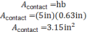
This calculation multiplies the assumed 5 in contact height by the 0.63 in guide-rail blade width to estimate the sliding interface area. The result is used as the denominator for each guide-shoe contact-pressure calculation.
Contact area:
GUIDE SHOE CONTACT PRESSURE
The average guide-shoe contact pressure, p, indicates how strongly the rail presses against the nylon sliding surface. It is calculated from p = F/A_contact, where F is the selected lateral load acting at one guide shoe and A_contact = 3.15 in2 is the estimated rail-to-liner contact area. Three load levels are checked to show how the average pressure changes as the local guide force increases.

GUIDE SHOE CONTACT PRESSURE – 125 LBF
For the 125 lbf guide-shoe case, F = 125 lbf is divided by the 3.15 in2 estimated contact area. This load corresponds to the per-shoe reaction obtained when the 500 lbf total lateral guide load is shared equally among four guide shoes, and it provides the primary distributed-load contact-pressure check.

GUIDE SHOE CONTACT PRESSURE – 250 LBF
The 250 lbf case is an additional local guide-shoe check using the same 3.15 in2 contact area. Here, F = 250 lbf represents a larger localized force than the evenly distributed per-shoe reaction. The calculation shows the corresponding increase in average pressure on the nylon liner.

GUIDE SHOE CONTACT PRESSURE – 500 LBF
The 500 lbf case is the highest local guide-shoe load considered in the contact-pressure checks. F = 500 lbf is divided by the same 3.15 in2 contact area to obtain a conservative average pressure for the nylon liner. This result is a preliminary static check and does not include wear, friction, lubrication, creep, heat, or nonlinear contact behavior.
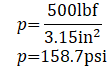
These contact pressures are low for a preliminary sliding shoe concept. Final guide shoe design should still account for wear, friction, lubrication, material creep, heat, guide rail finish, and replacement access.
GUIDE SHOE FEA BOUNDARY CONDITIONS
For the individual guide shoe FEA, the rear mounting face of the guide shoe was fixed. A lateral force was applied to one inner nylon slider face at a time. The opposite inner face and all exterior faces were left free.
The guide shoe load cases were:
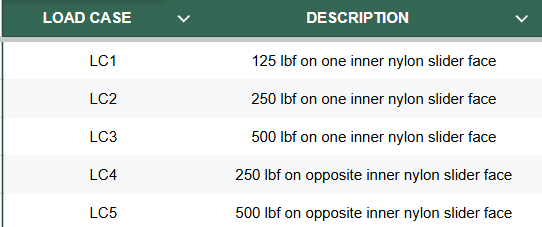
Guide Shoe FEA load conditions – Click for source table
GUIDE SHOE DESIGN SUMMARY
The sliding guide shoe design is appropriate for preliminary cab alignment and guide rail interface modeling. The nylon insert provides a simple replaceable sliding surface, and the steel housing provides the structural body. The guide shoe FEA should be interpreted as a preliminary local check because detailed friction, wear, lubrication, and nonlinear contact were not included.
GUIDE RAIL BRACKET DESIGN
This section discusses the following:
- Guide Rail Bracket Function and Load Path
- Guide Rail Bracket Design Summary
GUIDE RAIL BRACKET FUNCTION AND LOAD PATH
The guide rail brackets connect the T89/B-style guide rails to the lift shaft frame. These brackets are important because they transfer lateral guide forces from the rail into the shaft structure.
The guide rail bracket load path is:
Guide shoe force
- to guide rail blade
- to guide rail base
- to guide rail bracket
- to shaft frame
The bracket design must maintain rail alignment while avoiding interference with the guide shoes, fishplates, enclosure panels, and cab travel path.
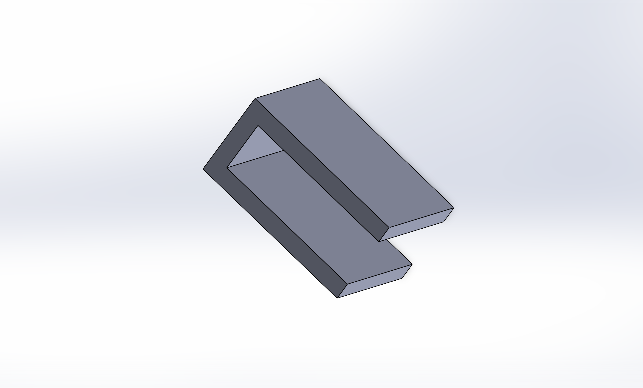
Guide Rail Bracket – Click to enlarge
GUIDE RAIL BRACKET DESIGN SUMMARY
The guide rail bracket provides the mechanical connection between the guide rail and shaft. In the current model, the bracket is suitable for layout and preliminary FEA. Future work should add final bolt or weld details, mounting hole sizing, washer contact, clamp preload, installation tolerances, and supplier-specific guide rail bracket requirements.
HYDRAULIC ROD-TO-CAB INTERFACE DESIGN
The hydraulic rod-to-cab bracket transfers the hydraulic lifting force into the cab chassis. This is one of the most important structural interfaces in the elevator model.
This section discusses the following:
- Hydraulic Connection Hand Check
- Pin Direct Shear Stress
- Conservative Pin Bending Stress
- Pin Stress Scaling to 2,500 lbf and Factor of Safety
- Pin Stress Scaling to 6,300 lbf and Factor of Safety
- Hydraulic Bracket FEA Setup
- Hydraulic Interface Design Summary
The hydraulic interface includes:
- Hydraulic rod or cylinder representation
- Rod-end or clevis-style connection
- Cab-side bracket
- Pin connection representation
- Cab bottom load-transfer region
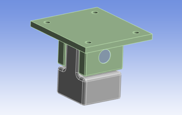
Hydraulic Rod to Cab Link – Click to enlarge
Here is the video tour:
VIDEO COMING: HOW TO ASSEMBLE THE HYDRAULIC END JOINT
SEE OUR HOW TO HELP AND/OR CROWDFUNDING CAMPAIGN PAGE TO HELP CREATE ALL THE TUTORIAL VIDEOS FASTER
HYDRAULIC CONNECTION HAND CHECK
The hydraulic rod-to-cab connection transfers the lifting force from the hydraulic system into the elevator cab. These hand calculations check the steel pin at that joint for the main ways it could be overloaded, including shearing across the pin and bending through its length. The results provide a simple strength check before relying on the FEA model.
An earlier pin/clevis style bracket check was performed using a 2,100 lbf reference load. The final nominal elevator load used later in the project was 2,500 lbf, so the original 2,100 lbf check should be treated as an initial calculation and updated if final dimensions change.
The initial check used the following dimensions:
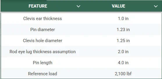
Hydraulic rod end dimensions – Click for source table
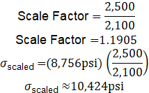
The scaling calculations and factors of safety are correct. Using the exact scale factor, 2,500 / 2,100 = 1.19048, gives a scaled conservative pin-bending stress of approximately 10,424 psi.
PIN DIRECT SHEAR STRESS
This calculation checks whether the hydraulic connection pin could be cut across its cross-section by the lifting force, similar to a bolt being sliced through. The applied load is divided by the pin’s shear area to estimate the internal stress. The result shows whether direct shearing is a significant concern.
This calculation evaluates average shear stress in the connection pin at the original 2,100 lbf reference load. It provides a simple baseline check of the pin cross-section before considering the more conservative effect of pin bending.
The pin direct shear stress at the 2,100 lbf reference load was:

CONSERVATIVE PIN BENDING STRESS
This calculation checks whether the hydraulic connection pin could bend because the load acts through the clevis and rod-eye connection rather than perfectly through one flat plane. Bending can create higher stress than simple shear in a pin. The conservative result is therefore used as the main reference stress for the later load-scaling checks.
This calculation uses the conservative pin-bending representation from the original bracket check to estimate von Mises stress in the pin. The bending result is treated as the more critical baseline stress and is scaled to the later project load cases.
The conservative pin bending von Mises stress was:

PIN STRESS SCALING TO 2,500 LBF AND FACTOR OF SAFETY
This calculation adjusts the previously calculated pin bending stress from the 2,100 lbf reference load to the 2,500 lbf nominal design load. It then compares the scaled stress with the assumed steel yield strength. The factor of safety shows how much strength margin remains at the nominal load.
This calculation scales the 2,100 lbf conservative pin-bending stress linearly to the final 2,500 lbf nominal elevator load. The scaled stress is then compared with the assumed 36,000 psi steel yield strength to obtain a preliminary nominal-load factor of safety.
Scaling the conservative pin bending stress from 2,100 lbf to 2,500 lbf
PIN STRESS SCALING TO 6,300 LBF AND FACTOR OF SAFETY
This calculation scales the same pin bending stress to the larger 6,300 lbf conservative load case. It represents a much more demanding condition and therefore gives a smaller strength margin. The resulting factor of safety helps show how close the pin comes to the assumed steel yield strength under this higher load.
This calculation scales the same conservative pin-bending stress to the 6,300 lbf higher load case. The resulting factor of safety shows the reduced margin at the conservative load and identifies the pin/clevis interface as a priority for detailed future validation.
For the 6,300 lbf conservative load case:
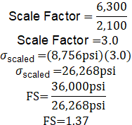
This indicates that the hydraulic rod-to-cab interface may be acceptable for preliminary nominal loading but should receive detailed future review under conservative and dynamic load cases. Pin bending, clevis bearing, edge distance, weld sizing, fatigue, and local plate bending should be checked before final design.
HYDRAULIC INTERFACE DESIGN SUMMARY
The hydraulic rod-to-cab bracket is a critical component and should be reviewed carefully in future work. The current model provides a load-transfer representation suitable for preliminary FEA, but final validation requires detailed pin, clevis, bearing, weld, plate bending, fatigue, hydraulic actuator, and connection checks.
ENCLOSURES, DOORS, AND HYDRAULIC LAYOUT
 The enclosure panels, door systems, and hydraulic layout components were added to complete the elevator assembly and support final rendering. These components improve the visual completeness and layout representation of the elevator system.
This section discusses the following:
- Shaft and Cab Enclosure Panels
- Cab and Shaft Door Systems
- Hydraulic Layout Components
SHAFT AND CAB ENCLOSURE PANELS
The shaft and cab panels were modeled using steel sheet material with thickness of 0.03847 in (20 gauge). These panels are treated as enclosure components rather than primary structural members.
CAB AND SHAFT DOOR SYSTEMS
The door systems were modeled for cab and shaft layout. They are not final validated door mechanisms. Future work should define tracks, rollers, interlocks, guides, safety clearances, and installation hardware.
HYDRAULIC LAYOUT COMPONENTS
The hydraulic components were modeled for layout and rendering. Detailed hydraulic pressure, bore, stroke, seal, fitting, pump, reservoir, and buckling checks were not completed in this stage.
FINITE ELEMENT ANALYSIS
Finite element analysis was performed in ANSYS Mechanical on critical components and assemblies. The FEA was used to evaluate stress and deformation trends and to confirm that the redesigned components had reasonable preliminary structural behavior.
The analyzed components and assemblies included:
- Guide shoes
- Guide rails
- Cab chassis
- Hydraulic rod-to-cab bracket
- Lift shaft
- Full lift assembly
The general FEA assumptions were:
- Structural steel was assigned to steel members.
- Nylon was assigned to guide shoe inserts.
- Bonded contacts were used for welded or simplified connection regions.
- Detailed bolts, weld beads, threads, washers, preload, and frictional slip were not modeled.
- Loads were applied as forces or distributed loads.
- Fixed supports were applied at representative mounting, base, or support regions.
- Mesh controls were applied around critical geometry, brackets, contact regions, and load-transfer areas.
- Results were reviewed using von Mises stress and total deformation.
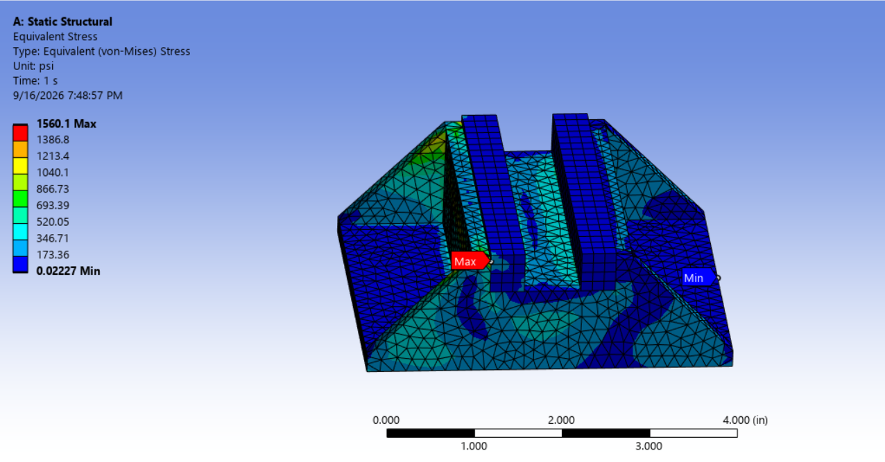
 How to read the FEA images: The colors show where the calculated result is highest and lowest within each model. Red marks the highest value on that particular plot and blue marks the lowest; red does not automatically mean that a part is failing. The numerical maximum must be compared with the material strength for stress plots and with acceptable movement or alignment limits for deformation plots.
GUIDE SHOE FEA RESULTS
The guide shoe FEA checked the nylon slider and steel housing under lateral loading. The rear mounting face was fixed, and the lateral load was applied to one inner slider face at a time.
The result images show:
- Von Mises stress in the guide shoe.
- Total deformation of the guide shoe.
- Stress near internal groove corners.
- Stress near the rear mounting face.
Guide shoe von Mises stress plot – Click to enlarge
The highest stress is concentrated at the inside corner of the U-shaped guide shoe, close to the region where the lateral force is transferred from the rail/slider into the housing. This type of local hotspot is expected where the shape changes suddenly and the force is carried through a smaller area. The maximum shown is 1,560 psi, which is below the preliminary strength values used for the steel housing and nylon insert, so this 250 lbf static load case does not show material yielding.
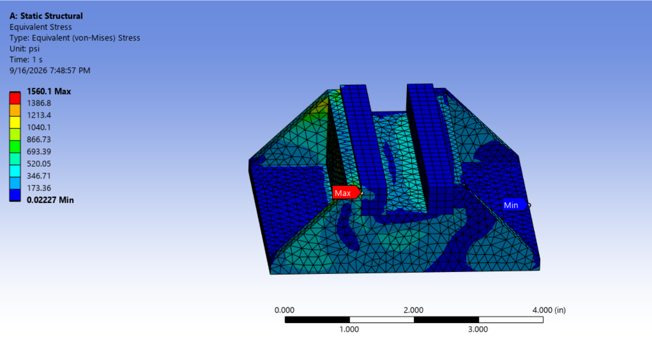
Guide shoe total deformation plot – Click to enlarge
The loaded inner slider moves the most, while the fixed mounting region moves almost none. The maximum movement is only 0.00038549 in, which is extremely small and indicates that the guide shoe is very stiff under the shown 250 lbf lateral load. This result is still preliminary because long-term wear, friction, lubrication, and nylon creep were not included in the model.
ANSYS result value:
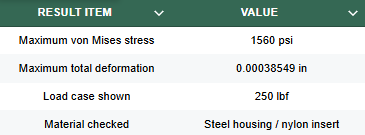
Guide Shoe FEA result – Click for source table
GUIDE RAIL FEA RESULTS
The guide rail FEA checked rail stress and deflection under lateral guide loading. The rail bracket locations were constrained, and lateral loads were applied to the guide rail blade.
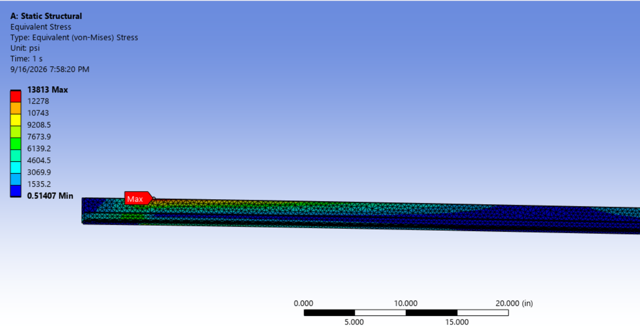
Guide Rail Stress plot – Click to enlarge
The stress is highest in the guide rail near the region where the sideways load is applied and then decreases as the load is carried toward the supported portions of the rail. The maximum stress is 13,813 psi, which is below the 36,000 psi steel yield strength assumed in this report. This means material yielding is not the main concern for the shown 250 lbf case; rail movement is the more important result to review.
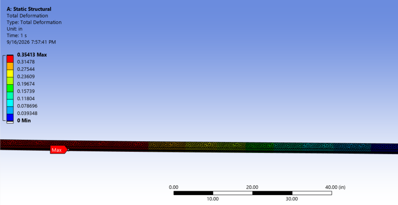
Guide Rail total deformation plot – Click for source Image
The guide rail bends sideways between its constrained support locations, with the largest movement occurring away from the most restrained region. The reported maximum lateral deformation is 0.35413 in, which is much larger than the deformation seen in the other analyzed components. Even though the stress remains below yield, this amount of movement could affect cab alignment or guide-shoe clearance, so guide-rail support and bracket spacing should be reviewed carefully.
ANSYS result:
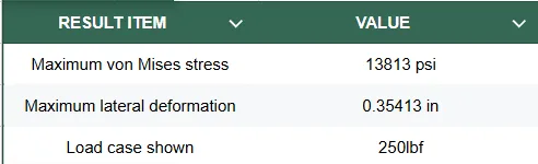
Guide Rail FEA result – Click for source table
CAB CHASSIS FEA RESULTS
The cab chassis FEA checked the cab frame under hydraulic loading. The analysis focused on the hydraulic load-transfer beams, vertical cab frame members, guide shoe mounting regions, and overall cab chassis deformation.
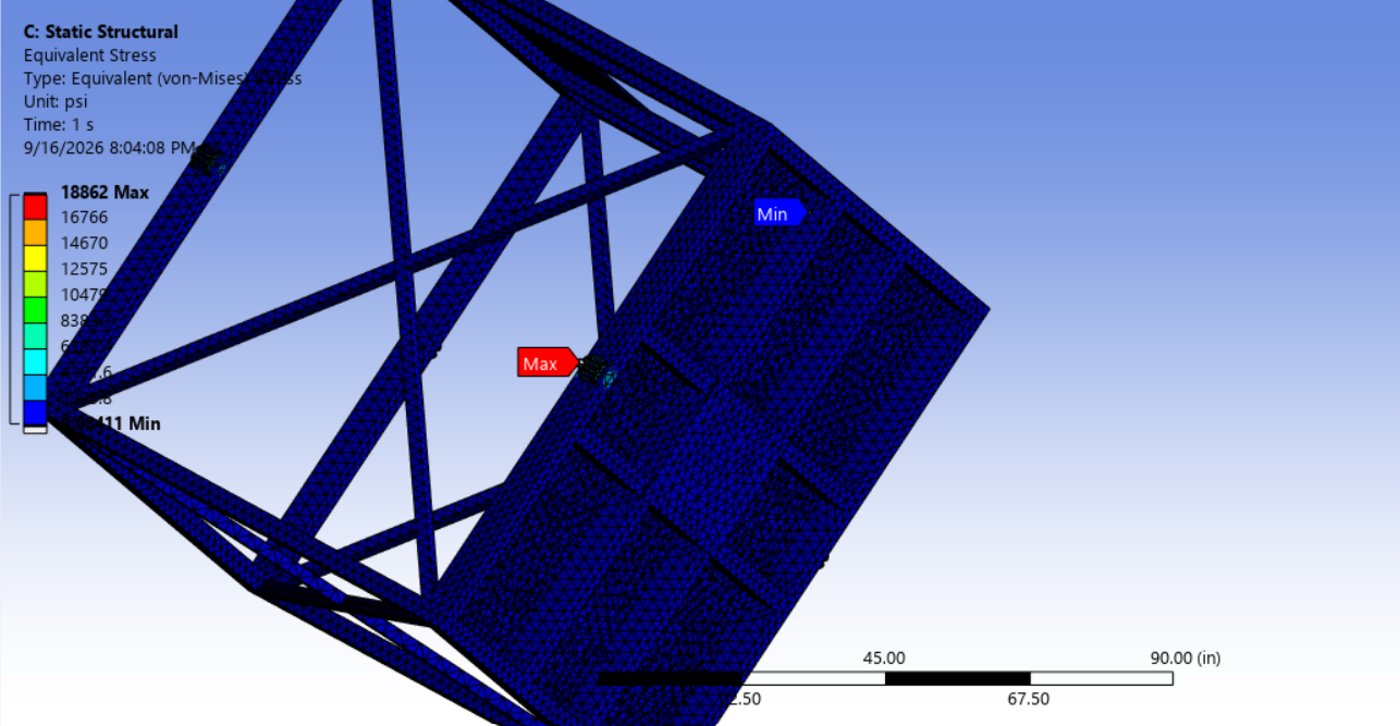
Cab chassis von Mises stress plot – Click to enlarge
Most of the cab chassis remains in the lower-stress colors, while the higher stress is concentrated around the bottom load-transfer region where the hydraulic force enters the cab and spreads into the frame. The maximum stress is about 880 psi, which is very low compared with the 36,000 psi steel yield strength assumed in the report. For the analyzed 2,100 lbf load case, the plot therefore supports the basic cab load-path concept, although final connections and higher load cases still require validation.
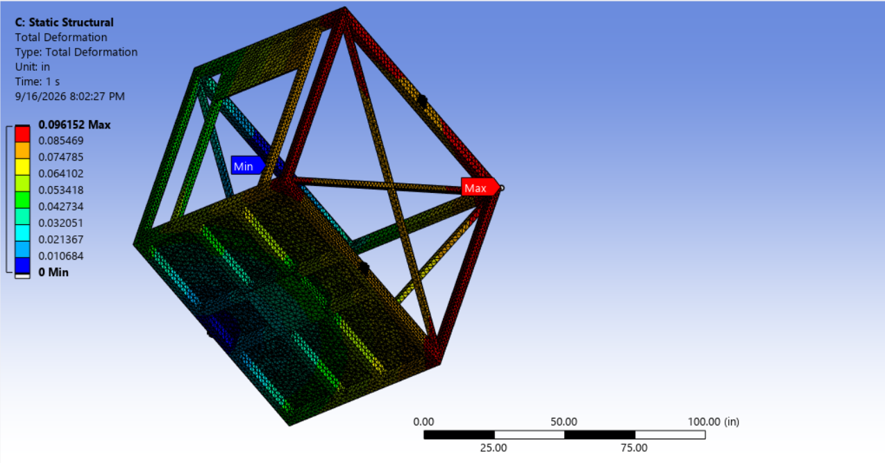
Cab chassis total deformation plot – Click to enlarge
The deformation is spread across the cab floor and supporting frame rather than appearing as one severe local bend, which indicates that the load is being distributed through the chassis. The result table states a maximum deformation of 0.04 in; however, the ANSYS color legend in the image appears to show approximately 0.00392 in. Because these two displayed values do not match, the original ANSYS result should be checked and one verified value should be used in the final report.
ANSYS result value:
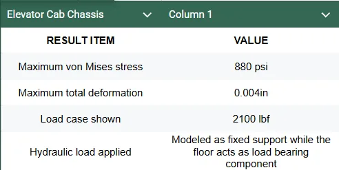
Elevator Cab FEA result – Click for source table
HYDRAULIC ROD-TO-CAB BRACKET FEA RESULTS
The hydraulic rod-to-cab bracket FEA checked the load-transfer region where the hydraulic lifting force enters the cab chassis.
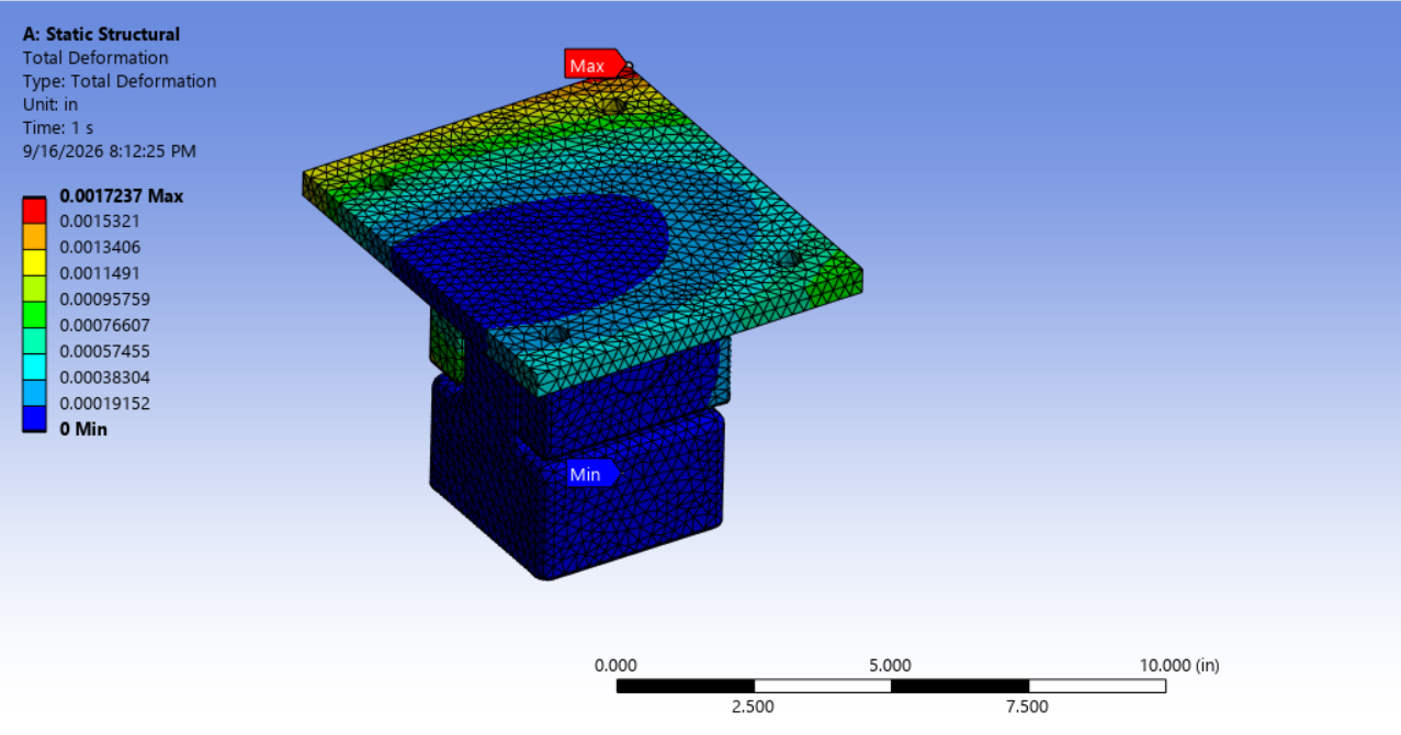
Hydraulic rod-to-cab bracket stress plot – click to enlarge
The highest stress is located in the central load-transfer region of the bracket near the change in shape between the upper plate/body and the lower connection. This is expected because the 2,100 lbf pushing force has to pass through this narrower transition before entering the cab structure. The maximum stress is 7,861 psi, which is below the assumed 36,000 psi steel yield strength, but the pin, clevis, bearing surfaces, welds, and fatigue behavior still need separate final checks.
The upper plate moves the most while the lower supported portion moves the least, showing a small amount of bending through the bracket as the hydraulic force is transferred upward. The maximum total deformation is only 0.0017237 in, so the bracket behaves very stiffly under the shown 2,100 lbf static pushing load. The small movement does not replace detailed checks of the connection hardware and weld regions.
ANSYS result value:
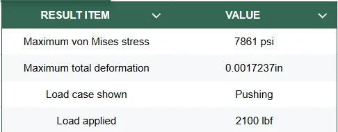
Hydraulic Rod End FEA result – Click for source table
LIFT SHAFT FEA RESULTS
The lift shaft FEA checked the redesigned shaft as a standalone hollow braced frame. The shaft was checked for stress, total deformation, lateral sway, and stress near guide rail bracket regions.
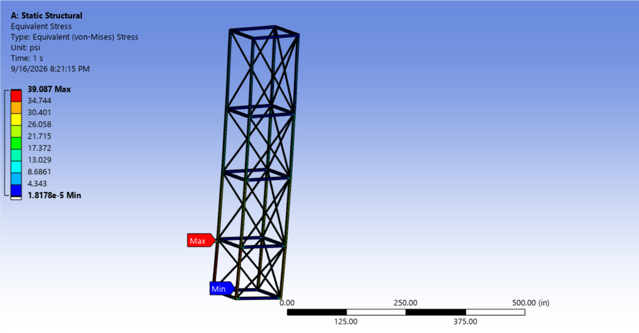
Lift shaft von Mises stress plot – Click to enlarge
Almost the entire shaft remains in the lowest-stress colors, with the small maximum occurring near the lower part of the frame where the load path and fixed-base condition create a local concentration. The maximum stress is only about 39 psi under the shown 250 lbf lateral load, far below the assumed steel yield strength. This indicates very low member stress in this simplified load case, although base anchorage, real joint stiffness, and final guide-rail reactions are not represented in detail.
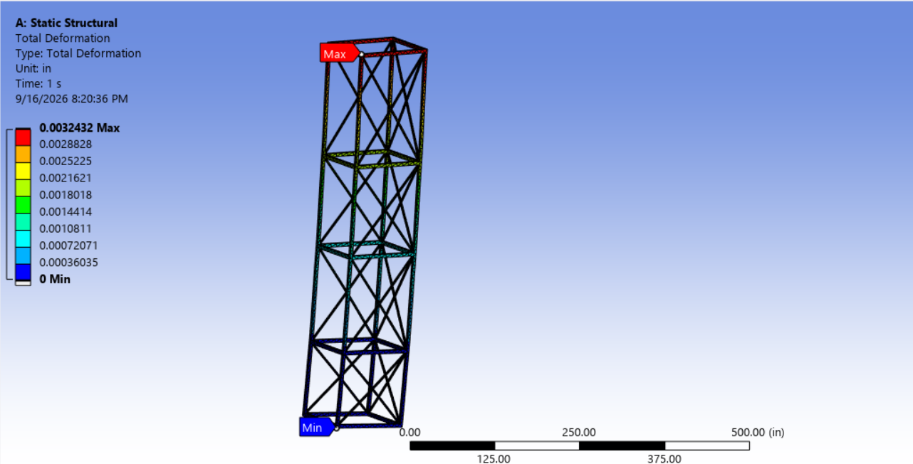
Lift shaft Deformation plot – Click to enlarge
The deformation pattern shows the shaft behaving like a tall braced frame: movement is smallest at the fixed base and gradually increases toward the top. The maximum movement is only 0.00324 in over the full shaft height, which indicates very little lateral sway in this simplified 250 lbf case. The result supports the value of the X-bracing, but final analysis should still include actual anchorage, connection stiffness, dynamic loading, and code-based lateral loads.
ANSYS result value:
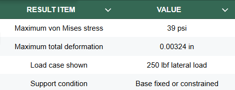
Lift shaft FEA result – Click for source table
FULL LIFT ASSEMBLY FEA RESULTS
The full lift assembly FEA checked the integrated behavior of the shaft, cab chassis, guide rails, guide shoes, brackets, and hydraulic interface. This analysis helps identify overall stress and deformation trends in the completed assembly.
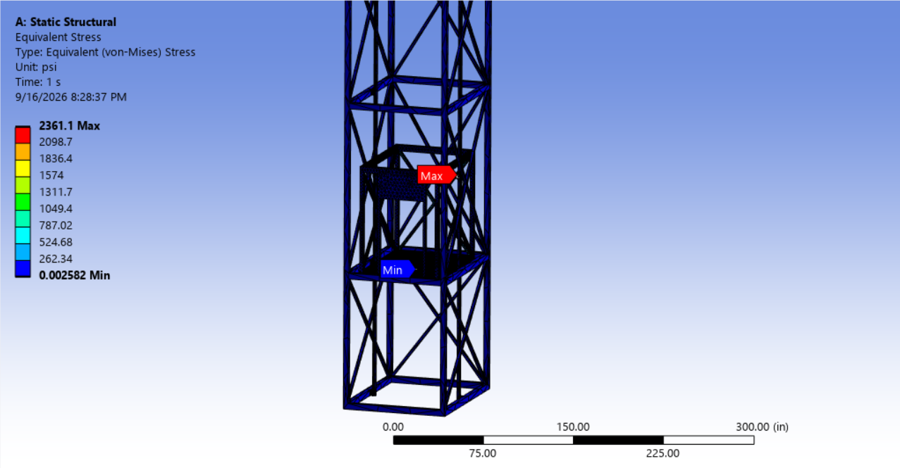
Full lift assembly von Mises stress plot – Click to enlarge
The highest stress is concentrated around the cab chassis and the interface between the guide system and the cab, where the vertical lifting load and sideways guide load meet. Most of the surrounding shaft remains at much lower stress. The maximum stress is 2,361 psi for the combined 250 lbf lateral and 2,100 lbf vertical load case, which is below the assumed steel yield strength and suggests a reasonable preliminary overall load path.
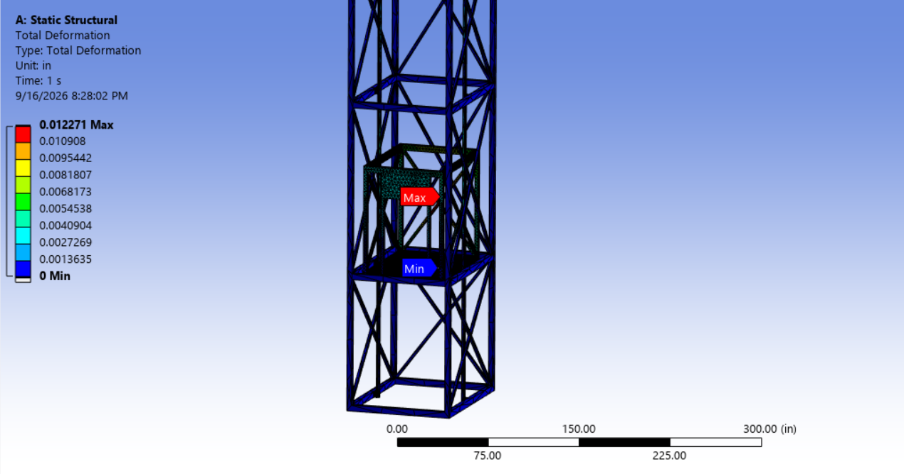
Full lift assembly deformation plot – Click to enlarge
The largest movement is localized around the cab/chassis and guide-interface region rather than appearing as a major sway of the entire shaft. The maximum total deformation is about 0.012 in under the combined lateral and vertical load case, which is small compared with the overall elevator dimensions. This is a useful preliminary indication of stiffness, but the bonded-contact assumptions and the absence of detailed clearances, bolts, welds, dynamic motion, and safety-system loads limit the final interpretation.
ANSYS result value:
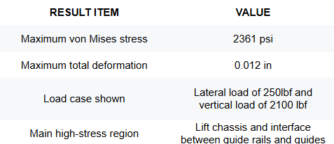
Complete lift assembly FEA result – Click for source table
FEA RESULTS SUMMARY
The FEA results should be interpreted as preliminary structural checks. The results are useful for identifying stress trends, deformation behavior, and load path behavior. They do not replace detailed final design validation because the model uses bonded/welded assumptions and does not include final bolted joints, weld sizing, hydraulic validation, dynamic loading, safety gear loading, or code compliance checks.
The current load cases and their results are as follows:
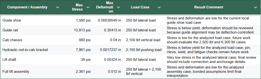
Complete FEA results – Click for source table
SOLIDWORKS ASSEMBLY GUIDE
This section explains the recommended SolidWorks assembly sequence for the elevator model. The assembly should be built from the fixed shaft outward because the shaft defines the guide rail locations, cab travel envelope, door locations, enclosure boundaries, and hydraulic alignment.
SOLIDWORKS ASSEMBLY SEQUENCE
The elevator assembly is designed around a centered and symmetrical layout. Major components such as the hydraulic actuator, guide rail mounting brackets, guide rails, and cab chassis should be positioned relative to the shaft centerline so that the left and right sides remain balanced and the guide system stays aligned. The cab enclosure walls are installed from inside the cab frame, while the exterior shaft panels are designed to fit the completed structure directly.
STEP 1: PREPARE THE LIFT SHAFT LOCATION AND HYDRAULIC ACTUATOR PIT
Prepare the building location and underground pit or enclosure required for the hydraulic actuator. The pit should be positioned so that the actuator can be installed approximately along the centerline of the elevator shaft and directly beneath the intended cab load-transfer region.
STEP 2: INSTALL AND ALIGN THE LIFT SHAFT STRUCTURE
Place the lift shaft structure in its intended building location. Confirm that the shaft is vertical, square, and properly aligned before securing it to the supporting structure.
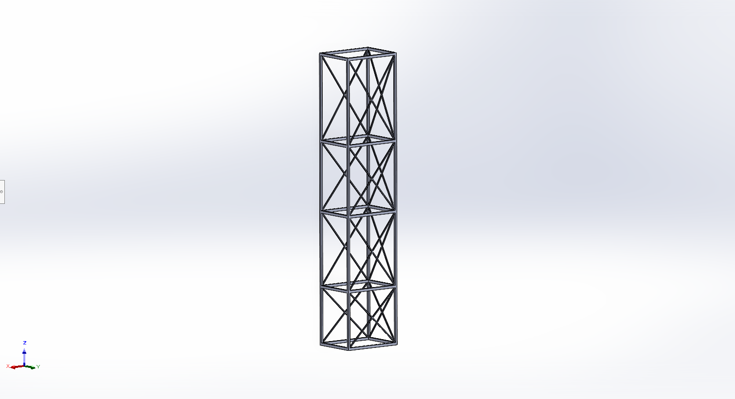
Step 2 Lift shaft Structure – Click to enlarge
STEP 3: POSITION THE HYDRAULIC ACTUATOR
Install the hydraulic actuator within the prepared pit or enclosure. Position it approximately at the center of the elevator cab footprint so that the hydraulic rod aligns with the cab’s bottom load-transfer structure.
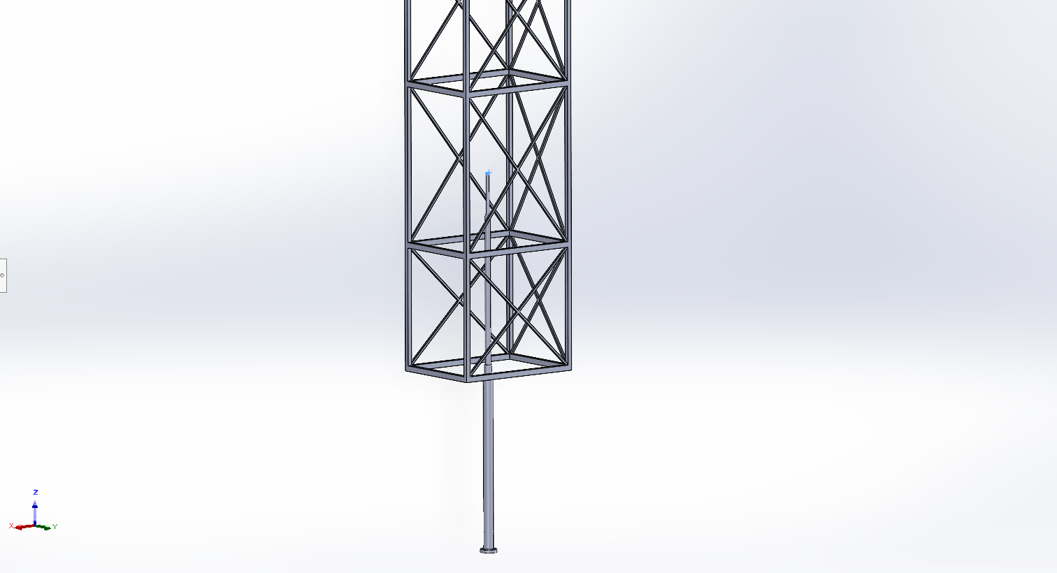
Step 3 Installed Hydraulic actuator – Click to enlarge
STEP 4: INSTALL THE GUIDE RAIL MOUNTING BRACKETS
Attach the guide rail mounting brackets to the lift shaft. The brackets should be positioned symmetrically so that they remain equidistant from the front and rear ends of the shaft and maintain the same alignment on both sides.
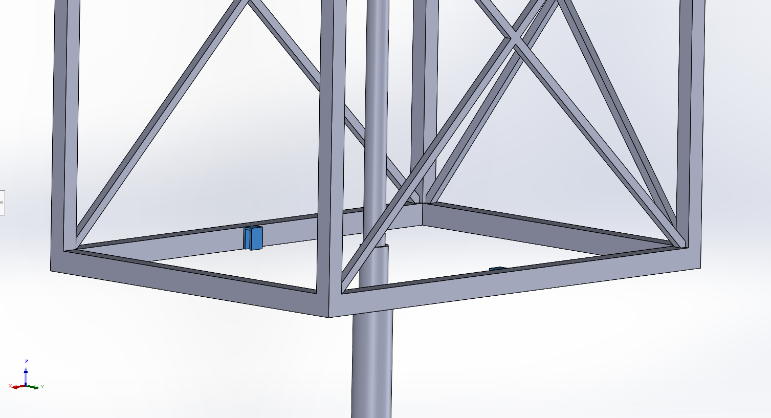
Step 4 image showing installed guide rail mounts – Click to enlarge
STEP 5: INSTALL AND CENTER THE GUIDE RAILS
Mount the guide rail sections onto their corresponding brackets using the provided bolt holes. Position the rails so that they are centered relative to the lift frame and remain equidistant from the front and rear of the shaft. Connect adjoining rail sections using the fishplates and verify that the complete rail runs are straight, parallel, and vertically aligned.
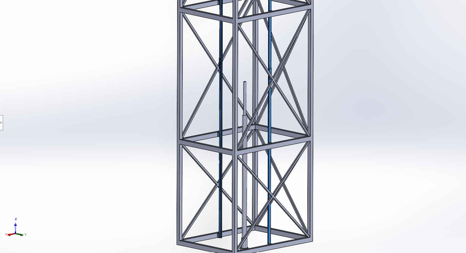
Step 5 image showing installed guide rails – Click to enlarge
STEP 6: BEGIN ASSEMBLY OF THE ELEVATOR CAB CHASSIS
Assemble the main elevator cab chassis outside the lift shaft. Verify that the frame is square and that the structural members remain centered and symmetrical before adding the door and enclosure components.
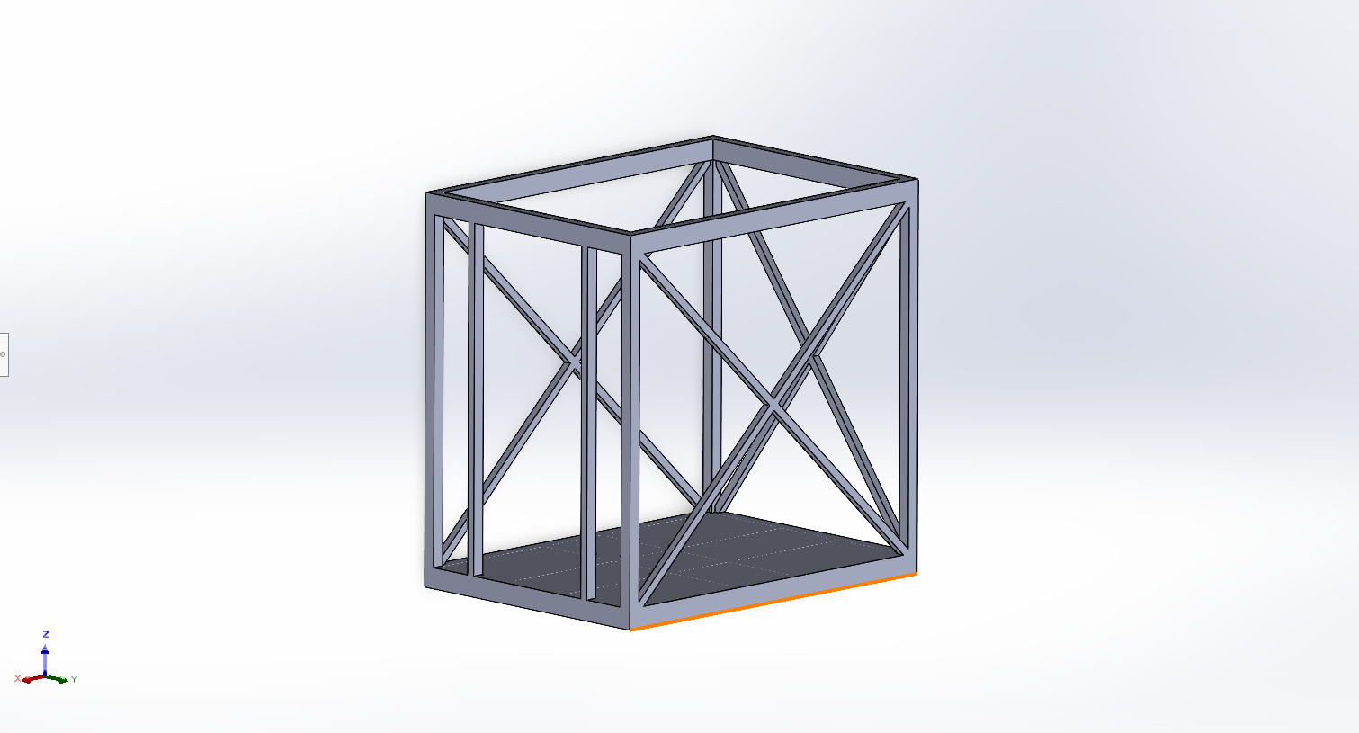
Step 6 image of elevator cab chassis with attached base plate – Click to enlarge
STEP 7: INSTALL THE CAB DOOR GUIDE RAILS
Attach the cab door guide rails to the chassis at their intended locations. Confirm that the rails are centered and aligned so that the door assemblies can move freely without interfering with the cab frame.
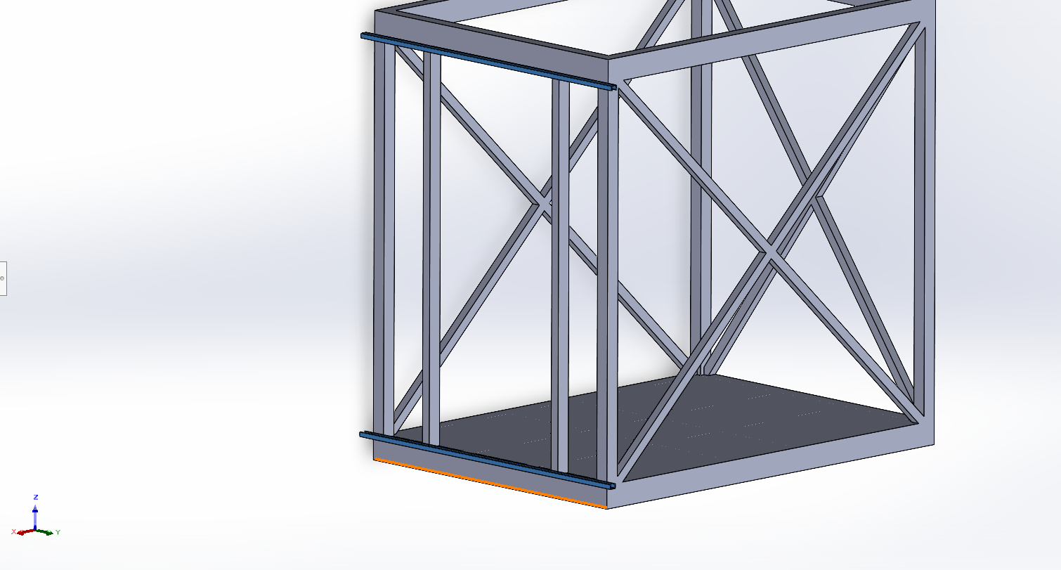
Step 7 image showing installed door guides – Click to enlarge
STEP 8: INSTALL THE CAB DOOR ASSEMBLIES
Install the door assemblies onto the cab door guide rails. Verify that both door components are properly seated and aligned with the cab opening.
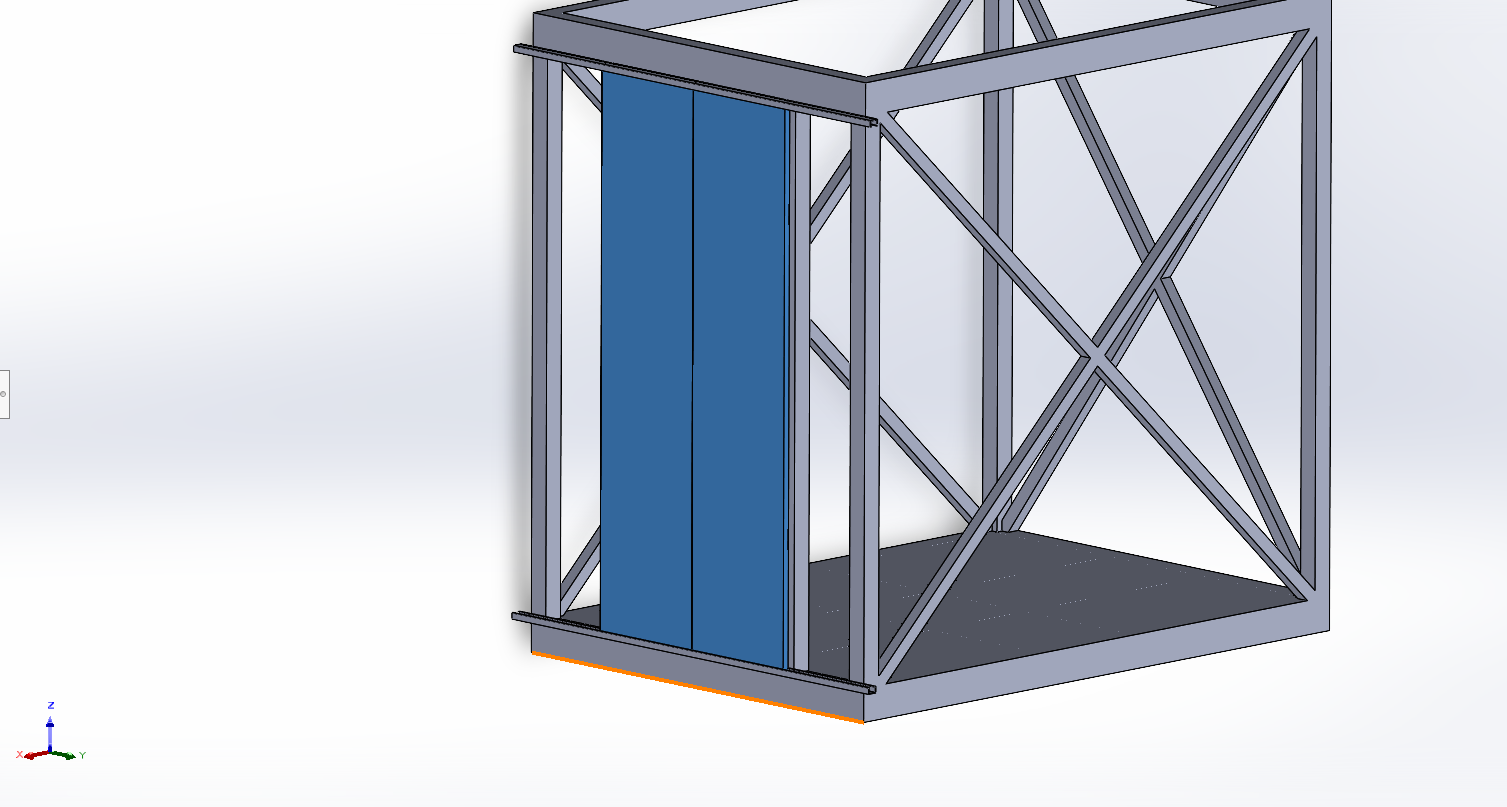
Step 8 doors installed into the guide rails – Click to enlarge
STEP 9: INSTALL THE BOTTOM LOAD-BEARING STRUCTURE AND LOAD-TRANSFER PLATE
Install the bottom structural members and central load-transfer plate. The load-transfer region should remain centered within the cab so that the hydraulic lifting force can be distributed evenly into the main structural frame.
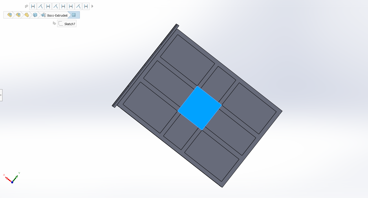
Step 9 image showing installed load bearing plate – Click to enlarge
STEP 10: INSTALL THE HYDRAULIC ROD-END CLEVIS BRACKET
Attach the clevis bracket to the bottom load-transfer region of the cab. Position the bracket so that it remains aligned with the hydraulic actuator centerline and does not introduce a significant lateral offset into the lifting load path.
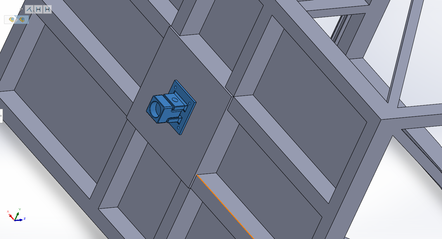
Step 10 image showing installed bracket – Click to enlarge
STEP 11: INSTALL THE CAB WALL PANELS FROM INSIDE THE CAB
Install the cab wall panels from the inside of the cab chassis. Position each wall panel against the structural frame and secure it so that the enclosure remains aligned with the cab geometry and does not interfere with the door system or guide components.
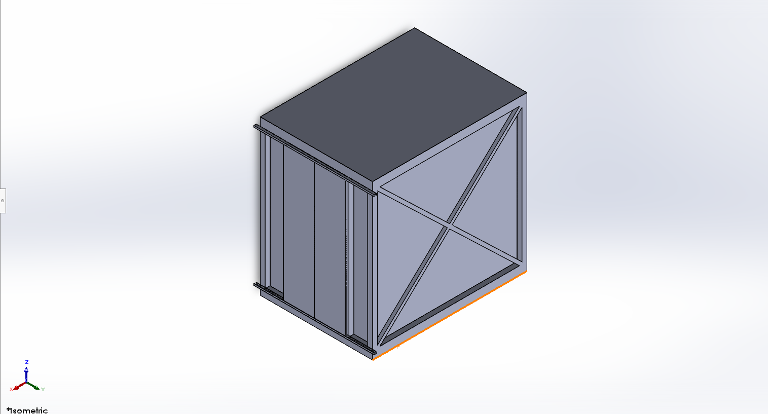
Step 11 image showing installed Panels – Click to enlarge
STEP 12: INSTALL AND CENTER THE SLIDING GUIDE SHOES
Install the sliding guide shoes on both the left-hand and right-hand sides of the cab. Each side should have one upper guide shoe mounted to the top structural member and one lower guide shoe mounted to the bottom structural member. Center each guide shoe so that its groove aligns directly with the corresponding guide rail blade.
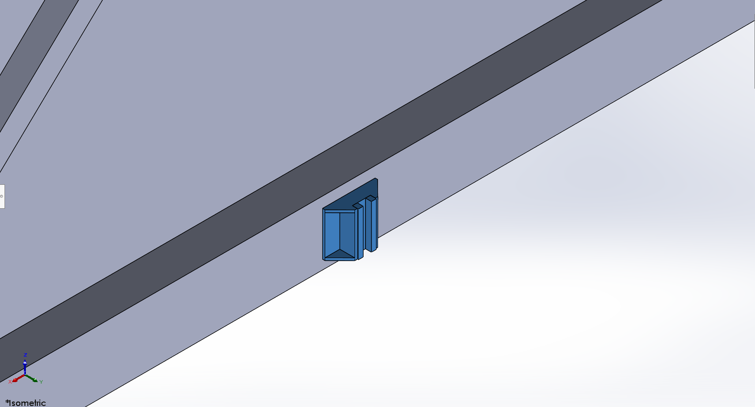
Step 12 image showing installed guide rail sliders – Click to enlarge
STEP 13: MOVE THE ELEVATOR CAB CHASSIS INTO THE LIFT SHAFT
Carefully move the assembled cab chassis into the lift shaft. Guide the cab into position so that the sliding guide shoes engage correctly with the guide rails on both sides.
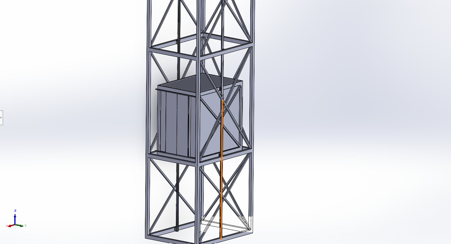
Step 13 image – Click to enlarge
STEP 14: VERIFY CAB, GUIDE RAIL, AND GUIDE SHOE ALIGNMENT
Confirm that the cab is centered inside the shaft and that the guide shoes sit evenly on the guide rails. The spacing between the cab and shaft should remain balanced from front to rear and from left to right, with no obvious binding or interference.
STEP 15: CONNECT THE CAB TO THE HYDRAULIC ACTUATOR
Align the hydraulic rod with the clevis bracket and complete the connection between the actuator and cab. Confirm that the actuator remains approximately centered beneath the cab and aligned with the central load-transfer structure.
STEP 16: CHECK OVERALL CAB TRAVEL AND CLEARANCES
Check the intended travel path of the cab within the shaft. Verify adequate clearance between the cab, guide rails, brackets, guide shoes, hydraulic components, and door assemblies throughout the expected range of motion.
STEP 17: INSTALL THE SHAFT DOOR ASSEMBLIES
Install the shaft doors at the required floor openings. Align each shaft door with the corresponding cab door so that the two systems line up correctly when the cab reaches each landing.
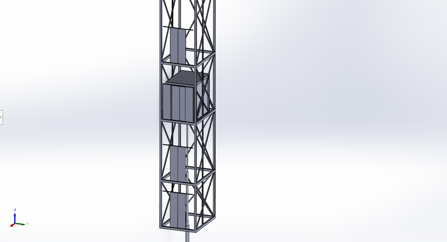
Step 17 image showing installed doors – Click to enlarge
STEP 18: INSTALL THE SHAFT ENCLOSURE PANELS
Install the shaft enclosure panels around the completed structure. These panels are designed to fit the shaft assembly directly, so they should be positioned according to their intended locations and secured after the internal structural and guide components have been aligned.
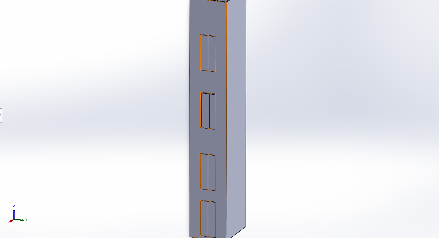
Step 18 image showing fully installed elevator – Click to enlarge
STEP 19: PERFORM THE FINAL ALIGNMENT AND FIT CHECK
Inspect the completed elevator assembly and verify that the major components remain centered and symmetrical. Confirm that the hydraulic actuator is aligned beneath the cab, the guide rails are centered within the shaft, the guide shoes engage properly, the cab walls are seated correctly from the inside, and the shaft panels fit the completed assembly without interference.
RECOMMENDED SOLIDWORKS CHECKS
After assembly, the following checks should be completed:
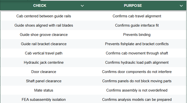
Solidworks – Click to source
Only the shaft or base reference should be fixed in the top-level assembly. The cab should not be fully fixed if motion rendering is needed. Overdefining the hydraulic jack and cab together should be avoided because it can prevent movement in the digital animation.
PHYSICAL ASSEMBLY GUIDE
This section describes the intended physical assembly sequence for the elevator concept. This is a preliminary assembly sequence for understanding how the major components connect outside the CAD model. It is not a construction or installation manual.
Here is the video tour:
VIDEO COMING: WALIPINI 3: TROPICAL HOUSE WALKTHROUGH
SEE OUR HOW TO HELP AND/OR CROWDFUNDING CAMPAIGN PAGE TO HELP CREATE ALL THE TUTORIAL VIDEOS FASTER
IMPORTANT PHYSICAL ASSEMBLY SAFETY NOTE
 This physical assembly sequence is for preliminary documentation only. The current model uses bonded or welded assumptions for FEA and does not include final bolt sizing, weld sizing, anchor design, hydraulic actuator validation, safety gear loading, dynamic loading, fatigue checks, installation procedures, or elevator-code compliance. The design should not be built, installed, or operated without review and approval by qualified elevator and structural engineering professionals.
FINAL ELEVATOR DESIGN
The final elevator model includes the redesigned lift shaft, redesigned cab chassis, guide rail system, sliding guide shoes, guide rail brackets, hydraulic rod-to-cab interface, enclosure panels, door systems, hydraulic layout components, final renderings, and digital movement representation. These components were integrated into the completed SolidWorks assembly to show the elevator layout, structural frame, guide system, hydraulic interface, enclosure arrangement, and door placement.
The lift shaft was redesigned as a hollow braced steel frame using HSS 4 × 4 × 0.25 main shaft members and HSS 2 × 2 × 0.1875 X-bracing. The redesign improves the shaft load path, reduces the unsupported length of the vertical members, and increases lateral stiffness for the guide rail support structure. The shaft frame provides the main support structure for the guide rail brackets, shaft enclosure panels, and elevator assembly layout.
The elevator cab chassis was redesigned to provide a clearer hydraulic load path and guide shoe mounting structure. The cab frame uses HSS 5 × 3 × 0.25 hydraulic load-transfer beams, HSS 3 × 3 × 0.25 vertical frame members, and an 18 × 18 × 0.50 in load-transfer plate at the hydraulic interface. This arrangement distributes the hydraulic load into the cab frame and provides structural mounting locations for the sliding guide shoes.
The guide rail system was modeled using a T89/B-style elevator guide rail profile. The guide rails were divided into three rail segments per side, with six total rail segments in the assembly. Backside fishplates were added at the rail joints to represent the guide rail connection method while keeping the guide shoe contact faces clear. The guide rails are used for cab alignment and lateral guidance, not as the primary vertical load-carrying structure.
The sliding guide shoes were designed to interface with the T89/B guide rail blade. Each guide shoe uses a steel housing and nylon sliding insert. Four guide shoes are included in the cab assembly, with upper and lower guide shoes on each side of the cab. The guide shoes transfer lateral guide loads between the cab frame and the guide rails.
The shaft and cab enclosure panels were modeled using 0.0387 in thick steel sheet, equivalent to 20-gauge sheet metal for the material standard used in this model. The enclosure panels are included for enclosure, visual representation, and assembly completion. They are not treated as primary structural load-bearing members in the current analysis.
The door systems and hydraulic layout components were added to complete the final assembly representation and support the renderings. These components show the intended layout and integration of the elevator subsystems. The hydraulic components are not a final actuator design, and the door systems are not final validated door mechanisms.
The completed model represents the current final design stage for this project. It includes the structural redesign, guide system, cab frame, hydraulic interface, enclosures, door layout, final renderings, and movement representation needed for documentation and review. The design remains a preliminary engineering model and requires detailed bolted connection design, weld sizing, hydraulic actuator validation, door mechanism validation, dynamic load analysis, safety system review, code review, and qualified professional approval before physical construction or operation.
FINAL DESIGN SUMMARY
The elevator assembly was developed into a more complete CAD and FEA-ready model. The lift shaft was redesigned as a standalone hollow braced structural frame. The cab chassis was redesigned to provide a clear hydraulic load path and guide shoe mounting structure. The guide rail system was developed using T89/B-style guide rails, segmented rail sections, fishplate joints, guide rail brackets, and sliding guide shoes.
The hand calculations support the main design decisions. The shaft calculations show that bracing is important for reducing unsupported column length and improving lateral stiffness. The HSS 2 x 2 x 0.1875 X-bracing shows acceptable preliminary axial stress and buckling behavior for the checked lateral load cases. The cab chassis calculations support the use of HSS 5 x 3 x 0.25 hydraulic load beams, an 18 x 18 x 0.50 in load-transfer plate, and HSS 3 x 3 x 0.25 vertical cab frame members. The guide rail calculations support a preferred guide rail bracket spacing of 60-80 in.
Finite element analysis was completed or prepared for the guide shoes, guide rails, guide rail brackets, cab chassis, hydraulic rod-to-cab bracket, lift shaft, and full lift assembly. The analysis used structural steel, nylon, applied load cases, bonded/welded assumptions, and representative boundary conditions to evaluate stress and deformation behavior.
The current model is suitable for preliminary design documentation, CAD review, structural sanity checking, assembly explanation, and future design development. It requires detailed connection validation, hydraulic validation, dynamic loading analysis, safety system design, tolerance review, code compliance review, and qualified professional approval before physical construction or operation.
RECOMMENDATIONS FOR FUTURE DESIGN IMPROVEMENTS
Future work should focus on replacing preliminary assumptions with detailed engineering validation. The following items are recommended before the design advances toward fabrication or construction:
- Confirm all final CAD member sizes and update the hand calculations.
- Replace bonded assumptions with detailed bolted, welded, or clamped connection models.
- Add bolt preload, washer contact, friction, and slip behavior where needed.
- Size welds and add weld symbols to manufacturing drawings.
- Verify guide rail and guide shoe dimensions using supplier data.
- Confirm guide rail bracket spacing with final load cases and supplier guidance.
- Perform mesh convergence studies on critical FEA regions.
- Validate hydraulic actuator bore, pressure, stroke, buckling, seals, and fittings.
- Review hydraulic rod-to-cab bracket pin bearing, pin shear, clevis stress, and fatigue.
- Add dynamic load factors for elevator motion.
- Check eccentric passenger loading on the cab chassis.
- Analyze safety gear and emergency braking loads.
- Review lift shaft anchorage, base reactions, lateral sway, and overturning.
- Validate enclosure panel attachment and service access.
- Define door tracks, rollers, hardware, and safety interlocks.
- Create detailed manufacturing drawings with tolerances and assembly notes.
- Review the design against applicable elevator and structural code requirements.
- Have the design reviewed by qualified structural and elevator professionals.
RESOURCES
The following project resources support this report:
- Completed SolidWorks elevator assembly.
- SolidWorks part files for the lift shaft, cab chassis, guide rails, guide shoes, guide rail brackets, hydraulic interface, doors, and enclosure panels.
- ANSYS Mechanical analysis files.
- FEA stress and deformation screenshots.
- Final rendered images of the elevator assembly.
- Open source elevator cost analysis
FREQUENTLY ASKED QUESTIONS
Is this report complete enough for construction?
No. This report is a preliminary engineering report for design documentation, CAD review, and structural sanity checking. It is not a final construction package. The design must be reviewed by qualified structural and elevator professionals before any physical construction or operation.
What carries the main vertical elevator load?
The hydraulic jack and cab chassis load-transfer structure are assumed to carry the main vertical load. The guide rails are used for lateral guidance and cab alignment.
Why was the shaft redesigned?
The shaft was redesigned so it could act as a standalone hollow structural frame. The redesign added a clearer load path, braced bays, guide rail support points, and improved lateral stiffness.
Why was bracing added to the shaft?
Bracing was added to reduce lateral sway, racking, and unsupported column length. The bracing calculations show that HSS 2 x 2 x 0.1875 X-bracing is reasonable for the assumed lateral load cases.
What members were used in the shaft?
The shaft calculations assume HSS 4 x 4 x 0.25 main vertical posts and horizontal ring members, with HSS 2 x 2 x 0.1875 X-bracing. If the final CAD uses different sizes, the calculations should be updated.
Why were T89/B-style guide rails used?
T89/B-style rails were used because they represent a realistic elevator guide rail profile. They are more appropriate for elevator cab guidance than a custom tube or I-beam.
What do the guide shoes do?
The guide shoes keep the elevator cab aligned with the guide rails during travel. They transfer lateral guide loads between the cab and guide rail system.
Why were sliding guide shoes used?
Sliding guide shoes were used because they are simpler to model and appropriate for preliminary guide alignment. Roller guide shoes would require additional details such as bearings, pins, preload, and roller contact behavior.
What material was used for the guide shoe slider?
The guide shoe slider was modeled as nylon. Nylon was used as a simple plastic sliding liner between the steel guide rail and the steel guide shoe housing.
Are the bolted joints fully modeled?
No. Bolted joints were not modeled in detail. Bonded or welded assumptions were used for the current finite element analysis.
Are the welds fully designed?
No. Welds were not sized or modeled as detailed weld beads. Welded behavior was represented using bonded assumptions for preliminary analysis.
Are the hydraulic components final?
No. The hydraulic components were modeled for layout and rendering. Hydraulic pressure, bore size, stroke, seals, fittings, buckling, and supplier data require future work.
Are the door systems final?
No. The door systems are included for assembly and rendering. Detailed door mechanism design, tracks, rollers, interlocks, and safety validation require future work.
Are the enclosure panels structural?
No. The enclosure panels are modeled as steel sheet panels for enclosure and visual representation. The main structural loads are intended to be carried by the shaft frame and cab chassis.
Why were bonded connections used in FEA?
Bonded connections were used to simplify the preliminary FEA setup. This allows early stress and deformation review, but it does not replace detailed bolt, weld, or clamp validation.
What should be done before final manufacturing drawings?
The design should be reviewed for final load cases, confirmed member sizes, weld sizing, bolt sizing, hydraulic actuator selection, guide rail supplier data, installation tolerances, door hardware, safety systems, and code compliance before final manufacturing drawings are created.
FINAL NOTE
This open source hydraulic elevator design package documents the completed preliminary CAD and FEA development work for the elevator assembly. The model includes a redesigned standalone shaft, redesigned cab chassis, guide rails, guide shoes, guide rail brackets, hydraulic interface, enclosures, doors, renderings, movement representation, hand calculations, and FEA setup for critical components and assemblies. The current work provides a clear basis for future engineering review and development, but it is not a final build-ready or code-certified elevator design.