 One Community
Earthbag Construction Footers, Foundation, and Flooring
This page is about the excavation and construction details of the footer, foundation, and flooring for earthbag dome constructions. It is meant to be the most complete, comprehensive, and easy to follow guide available. Once we’ve finished this tutorial and open sourced all the details for the 3-dome cluster as part of our crowdfunding campaign, we’ll do the same for the complete Earthbag Village (Pod 1) and Duplicable City Center®, and then the other 6 villages.
This guide consists of the following sections:
- What Is Earthbag Construction Footers and Foundation
- Why Open Source Footers and Foundations for Earthbag Construction
- Ways to Contribute and Consultants
- Section 1 Centerpoint Establishment
NOTE: THIS PAGE IS NOT CONSIDERED BY US TO BE A COMPLETE AND USABLE TUTORIAL UNTIL WE FINISH THE CROWDFUNDING CAMPAIGN AND ADD ALL THE VIDEOS AND EXPERIENCE FROM THAT BUILD TO THIS PAGE – IN THE MEANTIME, WE WELCOME YOUR INPUT AND FEEDBACK
HERE ARE LINKS TO WHO WE ARE AS AN ORGANIZATION (click icons for complete pages)


")
")
")
")
VISIT THESE DETAILED PAGES FOR MORE ON THE COMPLETE VILLAGE PLANS (click icons)
![]()

![]()
![]()
![]()
")
")
")
WHAT IS EARTHBAG CONSTRUCTION FOOTERS AND FOUNDATION
This page is about the excavation and construction details of the footer and foundation for earthbag construction domes. It is meant to be the most complete, comprehensive, and easy to follow guide available. One Community will be using the Earthbag Crowdfunding Campaign and construction of the Earthbag Village to make it even better. This will help to show people that sustainable and maximally space-efficient construction can be equally (if not more) beautiful than traditional building, artistic, significantly more affordable, and a much easier and realistic do-it-yourself project.
WHY OPEN SOURCE FOOTERS AND FOUNDATIONS FOR EARTHBAG CONSTRUCTION
![]() In order to push mainstream adoption of dome-home buildings, it is important to dispel the mystery around how these constructions work. We are demonstrating a clear path for replicating earthbag and other dome-home designs (like aircrete). Most builders have never had experience with earthbag or other dome-home constructions, so we are creating comprehensive resources that people can use to understand the complete process.
In order to push mainstream adoption of dome-home buildings, it is important to dispel the mystery around how these constructions work. We are demonstrating a clear path for replicating earthbag and other dome-home designs (like aircrete). Most builders have never had experience with earthbag or other dome-home constructions, so we are creating comprehensive resources that people can use to understand the complete process.
This article is part of our effort to put in one place all of the necessary resources for Dome-home replication. Our research demonstrated a huge lack of comprehensive resources in this area. We are providing an open source tool set that is both specific to this build and useful to other dome-home builds too.
WAYS TO CONTRIBUTE TO EVOLVING THIS SUSTAINABILITY COMPONENT WITH US
SUGGESTIONS â” CONSULTING â” MEMBERSHIP â” OTHER OPTIONS
CLICK THESE ICONS TO JOIN US THROUGH SOCIAL MEDIA
![]()
![]()
![]()
![]()
![]()
![]()
![]()
![]()
![]()
![]()
NON CORE TEAM CONTRIBUTORS TO THIS COMPONENT:
Hannah Copeman: Structural Engineer
Jennifer Lee: Graphic Designer (web design and editing for this page)
SECTION 1 CENTERPOINT ESTABLISHMENT
Here is the table of contents related to this section:
- 1.1 Introduction to Demarcation
- 1.2 Introduction to Safety Measures in Excavation
- 1.3 Demarcation of Construction Site
- 1.4 Centerpoint Establishment
1.1 INTRODUCTION TO DEMARCATION
We will start by marking the boundaries for excavation. This begins once the land has been surveyed by a licensed surveyor who can verify the site’s boundary. For a standard single 15′ diameter dome, which is approximately 177 sqft, it requires a small area roughly 20′ x 20′. The additional area considers the outer buttress (necessary when the the top of your dome floor is above 5′ 5″ below ground level), wall bracing, and set back around the dome. In our case we are constructing a 3-dome cluster with a 10′ radius patio, 4′ to 5.5′ (depending on the site’s climate conditions) below ground level for natural insulation. We will excavate an extra 2′ around the domes for working space. In the next few sections we explain in detail how to mark the centerpoint of the domes and install a compass to check the accuracy of each level and measurement throughout the dome’s construction.
1.2 INTRODUCTION TO SAFETY MEASURES IN EXCAVATION
 As per the Occupational Safety and Health Administration (OSHA), Personal Protective Equipment (PPE) is required for the safety of all personnel on the team. Additionally, fences and signage are required to demarcate the dangerous work areas on site. If a trench is created (OSHA defines a trench as a “narrow underground excavation that is deeper than it is wide, and not wider than 15 feet”) additional safety precautions will be followed according to OSHA’s Trench and Excavation Safety published information.
The person in charge of implementing and following safety rules is the Safety Officer duties, his duties include, but are not limited to:
- Daily trench inspections.
- Promote the use of personal protective equipment.
- Implement proper access and egress from the trenches and excavations.
- Define if cave-in protections are needed and implement them, soil composition and OSHA local regulations will define this.
- Signaling and training the crew to avoid keeping materials on the edge of the trenches.
- Look for standing water or other hazards.
- Follow other general trenching and excavation rules.
We must avoid keeping materials on the edge of the trench, look for standing water or other hazards, and follow general trenching and excavation rules. Furthermore, the main tools required to initiate site demarcation are a shovel, pulaski, chalk, clipboard with paper and pencil, surveyor stakes, hammer, permanent felt pen, bright-colored flagging ribbon, etc., as explained in the tools and materials section.
Excavation in different types of soil requires different methodologies; a standard excavation is 4′-5′ deep. Resources on excavation and trenching are available at the end of this document, where more information can be found. When constructing the domes there are many safety precautions that must be taken for excavation and trenching activities. OSHA regulates safety measures including, but not limited to, the use of heavy tools and equipment, storage of materials, and fire safety. When experimenting on your own, it’s important to be aware of the basic safety measures so that injuries can be avoided. At the end of a day’s work it’s good practice to clean up and organize the site. Sharp tools, nails, materials, etc. should be stored appropriately. Additionally, any electrical and inflammable materials should be marked and stored in a safe place. Again, refer to the OSHA reference in the resources section for more information.
Since our excavation will be at least 4′, use of a backhoe or excavator is suggested as it would be laborious and time-consuming to dig with a shovel. To demonstrate to others who do not have access to such equipment we will manually excavate to prove it is possible. Henceforth, we will likely utilize a backhoe or excavator. The excavation, however shallow, will require approval from the local building department and associated regulatory agencies. This is to ensure that the ground is clear of poisonous or flammable gas pockets that may result in health hazards and potential dangers if encountered. This detailed checklist set by the Associated General Contractors of America outlines when it is permissible to begin excavation.
1.3 DEMARCATION OF CONSTRUCTION SITE
Demarcation of the construction site is an important milestone because it establishes the dome’s boundary. It provides a central basepoint from which other measurements are taken and because of this, it is crucial to plan well. The centerpoint will be re-established at various levels as construction of the dome is underway. It will also be re-measured during the construction of the dome’s wall to confirm its accuracy. With other markings drawn, and as materials and team members gather on site, it is likely that a centerpoint error can carry over.
For the Earthbag Village consisting of eight 3-Dome Clusters, eight 6-Dome Clusters, and a Tropical Atrium, we have calculated that we will need at least 2.64 acres. However, this area may change based on the preferences of the village builder and its inhabitants.


VIDEO COMING OF: DEMARCATION OF YOUR DOME HOME CONSTRUCTION SITE
SEE OUR HOW TO HELP AND/OR CROWDFUNDING CAMPAIGN PAGE TO HELP CREATE ALL THE TUTORIAL VIDEOS FASTER
1.4 CENTERPOINT ESTABLISHMENT
This section outlines how to establish the centerpoint of the 3-Dome Cluster site. The centerpoint will serve as a base point when marking the centers of each dome.
VIDEO COMING OF: CENTERPOINT ESTABLISHMENT
SEE OUR HOW TO HELP AND/OR CROWDFUNDING CAMPAIGN PAGE TO HELP CREATE ALL THE TUTORIAL VIDEOS FASTER
1.4.1 THREE-DOME MARKING AND MASS EXCAVATION
Before excavating it is important to determine what type of soil is present at your site. Detailed in-situ tests will be conducted to determine the soil content. Based on the soil type, you might decide to alter the excavation plan. For more sandy soil, a trench must be supported from the sides to avoid caving in during excavation. This can be done by using plywood or aluminum-sheet supports; again, OSHA’s guidelines on Trenching and Excavation Safety provide more information on protective systems. On the other hand, clayey soil is more stable and may not require as much stabilization, while blasting may be required if rocks are encountered. Typically, the footer trench is shallow for an earthbag dome and the excavation is not very extensive. However, because we are building below grade for the added insulation effects, we will require increased labor over a grade level build.
VIDEO COMING OF: DOME MARKING AND MASS EXCAVATION
SEE OUR HOW TO HELP AND/OR CROWDFUNDING CAMPAIGN PAGE TO HELP CREATE ALL THE TUTORIAL VIDEOS FASTER
1.4.1.1 IDENTIFY SINGLE BUILDING SITE CENTERPOINT
Creating a balanced 3-dome cluster layout and maintaining uniform wall curvature and height during earthbag dome construction is accomplished first by establishing a single building site centerpoint. This will serve as the primary anchor point utilized to mark the centerpoints for the other domes in the cluster. It is located at the center of the proposed patio, which all three domes will share. The centerpoint of each dome will dictate its symmetry and overall shape.
To establish the site’s centerpoint, use a measuring tape to mark a 51′-3(3/4)” x 37′-9(3/4)” (or 51.31′ x 37.81′) rectangle as shown in Figure X below.

Figure X. Rectangular Dimensions of 3-Dome Cluster – Click here to open full image
To mark the centerpoint (P) see the below drawing, designate a point that is 12′-3″ above the midpoint of the x-axis, at 25′-7(â¦Å¾)” from the y-axis, as depicted in Figure Y. This designates the centerpoint, which is also the center of the patio that connects the three domes in the cluster. The centerpoint is in line with axis A-A and can be verified by taking measurements from different base points, established at the corners of the rectangular site, or from alternative set points.

How to measure distances on unleveled terrain: Click here to open enlarged image in new tab
To establish the centerpoint as an instrument to be used to achieve the desired geometry of our site and each dome, a swivel anchor is hammered into the centerpoint until the top circular plate is flush with the ground. A chain, 15′ minimum in length, is then attached to rotate freely around the 360° arc.
VIDEO COMING OF: DEMONSTRATING SWIVEL ANCHOR AND CONTROL COMPASS
SEE OUR HOW TO HELP AND/OR CROWDFUNDING CAMPAIGN PAGE TO HELP CREATE ALL THE TUTORIAL VIDEOS FASTER
As previously mentioned, the centerpoint of the 3-Dome Cluster is the center of the patio. The patio will have a radius of 10′, and a staircase with 12″ tread widths. To establish the boundary of the patio, the centerpoint instrument will be utilized by placing a piece of tape on the chain at 10′ (the patio radius) from the swivel anchor in the center. Walk this around the centerpoint to identify the boundary of the patio. Use paint, chalk, a shovel, or any other appropriate method based on the site conditions to mark the perimeter.

Figure Y. Centerpoint Establishment of 3-Dome Cluster – Click to open Full Image
VIDEO COMING: IDENTIFICATION OF SINGLE BUILDING SITE CENTERPOINT OF 3-DOME CLUSTER
SEE OUR HOW TO HELP AND/OR CROWDFUNDING CAMPAIGN PAGE TO HELP CREATE ALL THE TUTORIAL VIDEOS FASTER
1.4.1.2 IDENTIFY THREE INDIVIDUAL DOME CENTERPOINTS
Now the center of each dome can be determined. For the two bottom domes in the cluster, the center of each dome, P1 and P2, is located 16′ away from the main centerpoint, parallel to the x-axis. The center of the top dome, P3, is located 16′ above the patio centerpoint, parallel to the y-axis. Figure Z presents this information.
Similar to how the patio centerpoint was marked, each dome’s center should be marked with a peg, stick, chalk, paint, or any other suitable available object. Following the procedure outlined in Section 1.4.1.1 for setting up the centerpoint instrument, a swivel anchor and 15′ chain will also need to be constructed at the center of each dome (P1, P2 and P3). With tape placed on the chain at 7′-6″ (the dome radius) away from the center, each dome’s inner perimeter can now be marked.
")
Figure Z. Establishment of Dome Centers (P1, P2 and P3) – Click to open full image
VIDEO COMING: 3-DOME CLUSTER INDIVIDUAL CENTERPOINTS
SEE OUR HOW TO HELP AND/OR CROWDFUNDING CAMPAIGN PAGE TO HELP CREATE ALL THE TUTORIAL VIDEOS FASTER
1.4.1.3 CONFIRM ACCURACY OF EACH CENTERPOINT
The accuracy of each dome’s center can be confirmed by measuring the distance from P1 to P2, P2 to P3 and P3 to P1. The distance from P1 to P2 should be 32′ and the distance between P2 to P3 and P3 to P1 are both 22′-7(1/2)” (or 22.63′), as shown below in Figure A. If different dimensions are used, the distances between the center of the domes can be verified by applying Pythagorean’s Theorem. This theory states that the hypotenuse of a right triangle is equal to the square root of the sum of the two legs, each squared. In our case, the distance between P2 to P3 can be calculated as such using the theorem:


VIDEO COMING: CONFIRMATION OF 3-DOME CENTERPOINTS
SEE OUR HOW TO HELP AND/OR CROWDFUNDING CAMPAIGN PAGE TO HELP CREATE ALL THE TUTORIAL VIDEOS FASTER
1.4.1.4 DESIGNATE DOME WORK AREA OUTER BOUNDARY
Each dome has an inner diameter of 15′, a wall thickness of 15″, and thus an outer diameter of 17′-6″ (or 17.5′). In addition to this, an extra 2′ will be cleared for working space around the dome. For the patio, an additional 4′ will be added to the radius. This accounts for a 2′ parapet wall demarcating the patio, plus 2′ of working space beyond that. To mark the outer boundary of the work area for excavation, move the piece of tape on each of the dome’s instrumental chains to 10′-9″ (or 10.75′) away from the central swivel anchor. This length is the addition of the inner radius, 7′-6″, the 15″ wall, and 2′ of working space beyond that. For the centerpoint anchor, P, located in the center of the patio, move the tape on the chain to be 14′ away from the swivel anchor to designate the extra area to be excavated for working space around the patio. The outer boundary of the patio and the three domes defines the outer excavation boundary, as shown in Figure B. Note that the outer buttress around the dome is located above grade, therefore it will not take up space in the excavated 2′-wide additional work area.

Figure B. Area of Excavation – Accounting for Working Space – Click to open full image
VIDEO COMING: DESIGNATION OF 3-DOME WORK AREA OUTER BOUNDARY
SEE OUR HOW TO HELP AND/OR CROWDFUNDING CAMPAIGN PAGE TO HELP CREATE ALL THE TUTORIAL VIDEOS FASTER
1.4.2 6-DOME MARKING AND MASS EXCAVATION
A similar process will be followed for marking the domes and excavating the site of the 6-Dome Cluster.
1.4.2.1 IDENTIFY SINGLE BUILDING SITE CENTERPOINT
The same method as presented in Section 1.4.1.1, for identifying the centerpoint of the 3-Dome Cluster, will be followed here to identify the centerpoint of the 6-Dome Cluster. Again, use a measuring tape to mark a 76′ x 51′-3(3/4)” (or 76′ x 51.31′) rectangle as shown in Figure C.

Figure C. Rectangular Dimensions of 6-Dome Cluster – Click to open full image
To mark the centerpoint (P) of the 6-Dome Cluster, designate a point that is 38′ above the midpoint of the x-axis, at 25′-7(â¦Å¾)” from the y-axis, as depicted in Figure D.

Figure D. Centerpoint Establishment of 6-Dome Cluster – Click to open full image
VIDEO COMING: IDENTIFY SINGLE BUILDING SITE CENTERPOINT
SEE OUR HOW TO HELP AND/OR CROWDFUNDING CAMPAIGN PAGE TO HELP CREATE ALL THE TUTORIAL VIDEOS FASTER
1.4.2.2 IDENTIFY SIX INDIVIDUAL DOME CENTERPOINTS
To determine the center of each dome, start by locating the centerpoint of each 3-dome cluster within the 6-Dome Cluster. Each center will be located 12′-7″ above and below the site centerpoint, along the line of the midpoint of the rectangle’s x-dimension. For clarity, the centerpoint of the top 3-dome cluster is labeled as “P-Upper” and the centerpoint of the bottom 3-dome cluster is labeled as “P-Lower.” Figure E presents this information.

Figure E. Establishment of Cluster Centers – Click to open full image
P-Upper and P-Lower will serve as base points from which the centers of each individual dome will be established. Each dome center is located 16′ away from that cluster’s centerpoint – this is identical to the design of the 3-Dome Cluster in Section 1.4.1.2. Figure F provides a depiction of the final layout of the centers for the bottom 3-dome cluster (P1, P2 and P3) and top 3-dome cluster (P4, P5 and P6).
")
Figure F. Establishment of Dome Centers (P1, P2, P3, P4, P5 and P6) – Click to open full image
VIDEO COMING: 6-DOME CLUSTER INDIVIDUAL CENTERPOINTS
SEE OUR HOW TO HELP AND/OR CROWDFUNDING CAMPAIGN PAGE TO HELP CREATE ALL THE TUTORIAL VIDEOS FASTER
1.4.2.3 CONFIRM ACCURACY OF EACH CENTERPOINT
The accuracy of each dome’s center can be confirmed by measuring the distance between each centerpoint. For the bottom cluster of domes, the distances from P1 to P2 and P2 to P3 are both 22′-7(½)” (or 22.63′) and the distance from P1 to P3 is 32′. The distances are symmetric across point P for the centers of the upper dome cluster, as shown below in Figure G.
")
Figure G. Distances Between Dome Centers (P1, P2, P3, P4, P5 and P6) – Click to open full image
VIDEO COMING: CONFIRMATION OF 6-DOME CENTERPOINTS
SEE OUR HOW TO HELP AND/OR CROWDFUNDING CAMPAIGN PAGE TO HELP CREATE ALL THE TUTORIAL VIDEOS FASTER
1.4.2.4 DESIGNATE DOME WORK AREA OUTER BOUNDARY
Similar to how the outer work area was established for the 3-Dome Cluster in Section 1.4.1.4, the 6-Dome Cluster will also have an additional 2′ excavated around the dome for working space. The domes and patios in the 6-Dome Cluster will have the same dimensions as the domes and patio in the 3-Dome cluster; therefore the tape on the centerpoint chain should be placed at 10′-9″ (or 10.75′) away from the swivel anchor for P1, P2, P3, P4, P5 and P6 and 14′ away from the swivel anchor for P-Upper and P-Lower. The outer boundary of the domes defines the outer excavation boundary, as shown in Figure H. Note that the additional excavation around the domes also encompasses the patio excavation. The entire area as labeled by “Area of Excavation” in Figure H is to be excavated 5′ deep; this will be discussed in further detail in Section 2.

Figure H. Area of Excavation – Accounting for Working Space – Click to open full image
VIDEO COMING: DESIGNATION OF 6-DOME WORK AREA OUTER BOUNDARY
SEE OUR HOW TO HELP AND/OR CROWDFUNDING CAMPAIGN PAGE TO HELP CREATE ALL THE TUTORIAL VIDEOS FASTER
1.4.3 CROWDFUNDING CAMPAIGN 3-DOME CLUSTER
A third cluster that may be built is the 3-Dome Cluster design that has been created for the Crowdfunding Campaign (CFC). This cluster differs from the previous two because it includes a wet dome that features a bathroom and small kitchen.
To identify the site center point, follow the same method as was outlined for the 3- and 6-Dome Clusters. The wet dome in the CFC cluster is smaller in size than the living domes and the two living domes are located slightly closer to each other, as shown in Figure HH. Therefore, the building area will be smaller – at a size of 34′-7 ⦝” x 49′-2 ⦺”.
To mark the site centerpoint (P), designate a point that is 12′-10 7/16″ above the x-axis and 24′-7″ from the y-axis. This centerpoint also marks the center of the patio. Similar to the other domes, the center point of each dome will also be established. The centerpoint of the bottom two domes in the cluster, with centers P1 and P2, are each located 15′-0″ away from the site centerpoint, P. The wet dome’s centerpoint is located 14′-0″ feet above the site centerpoint. Figure HH presents this information.
Similar to how the patio centerpoint was marked, each dome’s center should be marked with a peg, stick, chalk, paint, or any other suitable available object. Following the procedure outlined in Section 1.4.1.1 for setting up the centerpoint instrument, a swivel anchor and a chain are also required at the center of each dome. The two living domes, with centers P1 and P2 will have 15′ chains – similar to the previous 3- and 6- Dome clusters because they are 15′ tall on the interior with 1′ of wall thickness, making it 16′ in height total. The wet dome will need an 11′ chain because it is 11′ tall on the interior with 1′ of wall thickness, making it 12′ in height total. The two living domes will have interior diameters of 15′ and the wet dome will have an 11′-6″ interior diameter. With tape placed on the chain at 7′-6″ for P1 and P2 (the dome radius) and 5′-¾” for P3 (the dome radius) away from the center, each dome’s inner perimeter can now be marked.
Similar to the 3- and 6-Dome clusters, the accuracy of each centerpoint can be confirmed and an outer work area boundary around the domes can be designated. Refer to Section 1.4.1.3 and Section 1.4.1.4 to follow the outlined processes for the 3-Dome cluster; adjust the distances as necessary for the CFC site.

Figure HH. Crowdfunding Campaign 3-Dome Cluster – Click to open full image
VIDEO COMING: CROWDFUNDING CAMPAIGN 3-DOME CLUSTER
SEE OUR HOW TO HELP AND/OR CROWDFUNDING CAMPAIGN PAGE TO HELP CREATE ALL THE TUTORIAL VIDEOS FASTER
SECTION 2 EXCAVATION
The depth and width of excavation is determined by factors such as the site’s frost line, groundwater table depth, and type of soil. Ultimately, the excavation code of the site’s location will govern. The components related to the excavation process are as follows:
2.1 MASS EXCAVATION
The excavation process for preparing the building site is time-consuming and laborious. It can be expedited by using a backhoe; however, to demonstrate the versatility of our project we will provide instructions on how to manually excavate the site. Shovels and pulaskis will be used to show that although more time-consuming, the excavation process can still be completed in a practical manner without the use of heavy equipment and machinery.
Due to the strenuous nature of manual excavation, we recommend that proper techniques be followed in order to minimize the stress and strain associated with arduous manual labor. A suitable method can prevent physical back strain and potential injury. The following video presents safe shoveling tips for manual excavation and is highly recommended before beginning on-site work:
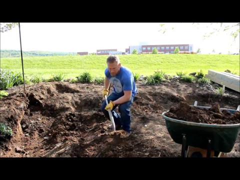
VIDEO COMING: PROPER PULASKI/SHOVEL TECHNIQUES – THIS SHORT DEMONSTRATION WILL SHOW HOW TO REDUCE BACK STRAIN, USE LOWER BODY STRENGTH WHEN SHOVELING, AND FOCUS ON PACING ONE’S SELF
SEE OUR HOW TO HELP AND/OR CROWDFUNDING CAMPAIGN PAGE TO HELP CREATE ALL THE TUTORIAL VIDEOS FASTER
With the site cleared, prepared, and outer boundaries delineated, mass excavation of the site can begin. There are two options for how deep the dome and its work site will be excavated. The first dome design employs a 1′-6″ buttress wall and has the floor of the dome 4′ below grade; thus requiring a 5′ mass excavation. The second dome design does not require a buttress wall and therefore must be set further below grade to achieve the same structural stability. The floor of this dome will be 5′-6″ below grade, requiring a 6′-6″ mass excavation.
For domes located in warmer climates, such as those in climate zones 1A though 4C (as defined by ANSI/ASHRAE/IESNA Standard 90.1), the first dome option is recommended1. For domes located in colder climates such as climate zones 5A through 8, the second dome design option is recommended. The second dome option is recommended for building in colder climates because it locates the footer and foundation of the dome further below the soil’s frost line. The frost line is the depth at which groundwater and moisture in the soil is expected to freeze. It is important to build the footing below frost line because the ground will act as a natural barrier that insulates and protects the soil from freezing around the footer during the winter. In the first dome design, the frost line is located 3′-6″ below the ground level and the foundation starts about 6″ below the frost line; whereas in the second dome design the frost line is located 4′-6″ below grade and the foundation starts 1′ below the frost line. The two design options are the same for both the 3-Dome and 6-Dome Cluster.
2.1.1 DOME DESIGN OPTION NO. 1
If the dome is to be built in warmer climates, the site is to be mass excavated to the area shown in Figure B, for the 3-Dome Cluster and Figure H, for the 6-Dome Cluster. This area accounts for the 7.5′ (inner) radius domes, 10′ radius patio and 2′ of additional working space around each dome. The mass excavation will be 5′ deep across the entire working area; this can be completed using a backhoe if available. The domes will be set into the earth for additional structural support and to take advantage of the earth’s natural insulation and thermal mass. An additional excavation that is 1′ deep will be dug around the perimeter of each dome to accommodate the footer. This will be discussed in further detail in Section 2.4 and Section 2.5.
VIDEO COMING: IMAGE OF THE SITE AFTER EXCAVATION OF DOME DESIGN OPTION 1 WAS COMPLETED, IT HIGHLIGHTS THE DIFFERENT LEVELS WITH TEXT OVERLAPPING THE IMAGE
SEE OUR HOW TO HELP AND/OR CROWDFUNDING CAMPAIGN PAGE TO HELP CREATE ALL THE TUTORIAL VIDEOS FASTER
2.1.2 DOME DESIGN OPTION NO. 2
If designing the dome to be located in colder climates, the site is still to be mass excavated to the areas shown in Figure B and Figure H, for the 3-Dome and 6-Dome Cluster respectively. However, the buttress wall that is called out in Figure B and Figure H will not be included – as shown below in Figure L, because Dome Design Option No. 2 does not require a buttress wall. With the domes set further into the ground, the mass excavation will be 6′-6″ deep across the entire working area. Similar to the first dome design option, an additional 1′ deep excavation is needed around the perimeter of each dome for placement of the footer.
One Community’s Original photo Is Coming: Image of the site after excavation of dome design option 2 was completed, it highlights the different levels with text overlapping the image.
2.2 UTILITIES
This section outlines the excavation required for utilities on site. Utilities will consist of plumbing and electrical such as electric power lines, cables, water access, telephone/ communication cables, sewer and drain lines, reclaimed water lines, irrigation purposes, etc. The depth depends on the utility type and the local building codes. Before excavating it is important to call 811, the national call-before-you-dig phone number, at least two days prior to digging and explain where you intend to dig. This is a free service in which workers mark existing utility lines on site. This is an important and required step to prevent accidental severing/damage of any existing utility lines. The markings are an important factor that may alter design plans.
Check with your local authorities for code requirements and recommendations for utility trench depths and other information such as gravel and conduit requirements or multiple utilities in the same trench. Each geographical location will have different code recommendations that must be taken into consideration.
The design frostline that we used for the dome in this tutorial is 4′-6″ below grade. Depending on the frostline of your site, we recommend constructing the foundation below the frostline, with the foundation at least 6″ below the frostline for dome Option 1, for warmer climates, and at least 1′ below the frostline for dome Option 2. It’s important to identify the frost depth of your site because frost heaving, which occurs above the frost line, can damage the structure of the dome by moving the foundation. Therefore, it is crucial to build the foundation below the frost depth in colder climates where frost heave is prevalent.
For reference, in our site’s county the building permit packet contained the frost line depth. However, that was for a general location in the area; our specific site is about 1430′ higher in elevation, at roughly 6500′, with no conclusive records relating to it. Therefore, we researched local elevations with known frost line depths within a few hundred miles of our site, and averaged several values with geographical similarities to provide what we expect is a reasonable representative figure. This resulted in an additional 6″ frost line depth increase due to the higher elevation. With an approximate elevation of 6500″, our estimated frost line depth is 4′-6″; thus design Option 2 will be used in this tutorial.
Later, in a conversation with one of the local soil scientists, we provided our process of determination, with the increased depth result, and received confirmation that our calculations are realistic. Additionally, selecting a deeper depth is a more conservative approach than selecting a depth that is closer to the frostline. Most permit packets contain, but are not limited to, the minimum requirements needed to obtain and hold a building permit. When in doubt of the building code or other information relating to building requirements, contact your local jurisdiction for clarification.
The frost line depth is crucial because water lines must be placed deep enough below the frost depth to prevent freezing. Because of their relatively shallow depth, the utility line trenches will be excavated manually with pulaskis and shovels. The excavated soil will be set aside and returned to the trenches after the utility lines have been installed. The remaining excess soil will be used as backfill above original grade for the stem walls.
The optimal distance to place the removed soil from the trenches is still to be defined and shared here, this will be the minimum distance so the effort moving the soil is minimal but should be enough to prevent any cave in or washing. To ensure safety during this process, follow the Trenching and Excavation Safety guidelines set by OSHA and the Utility Construction Safety guidelines set by the Associated General Contractors of America, this would be best done by the engineers and the safety officer.
VIDEO COMING: UTILITY EXCAVATION
SEE OUR HOW TO HELP AND/OR CROWDFUNDING CAMPAIGN PAGE TO HELP CREATE ALL THE TUTORIAL VIDEOS FASTER
2.3 ADJACENT WORK AREA
As previously mentioned in Section 1.4.1.4 and Section 1.4.2.4, the mass excavation provides for an additional 2′ of working space around each dome’s outer perimeter. It is important to minimize the excavation around the dome in order to keep as much of the soil’s original compaction in place. The surrounding soil serves as a structural support for the dome by preventing an outward kick-out motion at the bottom of the dome. The outer excavation boundary and work space designation for each design option of the 3-Dome cluster are shown in Figures I and J. The two design options for the 6-Dome Cluster will follow the same excavation layout.

Figure I. Areas of Excavation – Option No. 1 – Click here to open full image

Figure J. Areas of Excavation – Design Option No. 2 – Click here to open full image
2.4 FOOTER
With the mass excavation complete, reestablish the compass-serving swivel anchor at the excavated level. Use the compass to re-mark the inner diameter of each dome by tracing the perimeter at 7.5′ from the dome’s centerpoint. Next, dig a trench that is 24″ wide and 12″ deep, centered 8′ away from the dome’s center. This distance will make the footer centered with the 12″ wide earthbags above it. A two-foot wide footer is advised because it is approximately 20° wider, or about 8″ wider, than the foundation above it, which is 16″ wide as shown in Figure JJ. For a typical home, it is recommended to have the footer approximately 30° wider than the foundation 2. However, because we are limited to a 1 story dome with earthbag construction, we have used our engineering and construction judgement to use a 20° width increase instead. Consult a local engineer or builder to confirm a width reduction if straying from the 30° recommendation. This width increase is calculated with the following formula based on the right triangle diagram in the following Figure J2:
Width Increase = tangent(20°) * Foundation Height
Width Increase = tangent(20°) * 12″ = ~4.4″
For uniformity, we have rounded down to an increase of 4″ on either side of the foundation. The total width increase is 2 times 4″ = 8″.

Figure J2. Right Triangle of Foundation-Footer Width Increase
To further explain this calculation, refer to the informative video linked here, which explains the concept of using one leg and an angle of a right triangle to calculate the other leg of that right triangle. This calculation can be performed on any calculator that has the trigonometric functions of sine, cosine and tangent as explained and shown in this tutorial. If a calculator is not available, the website WolframAlpha can be used. On this site, type the equation into the ‘What would you like to know about?” search bar at the top left corner of the page and enter the equation as shown in the following Figure J3. The result of 4.4 is shown under ‘Decimal Approximation.’

Figure J3. Sample Calculation on WolframAlpha – Click to open results on Wolfram Alpha
This ensures that the footer can adequately distribute the stress profile that the foundation imposes on it2. The footer will be the bottom layer in the 6′ deep trench excavation for Design Option No. 1 or the bottom layer in the 7′-6″ trench excavation for Design Option No. 2. Follow this procedure for each dome in the 3-Dome and 6-dome Cluster.

Figure JJ. Footer Width Relative to Foundation Width – Click here to open full image
The additional 24″ x 12″ trench that is to be excavated around the dome’s inner perimeter accounts for the footer. Check with OSHA’s Trench and Excavation Safety published information and your local engineer to verify the stability of the trench. Depending on the soil type, the trench may need to be wider than 24″ and may also need additional support. The footer supports the foundation and footer + foundation supports the trench-bearing stem wall of the dome. The footer will be composed of compacted gravel and geotextile fabric, to allow the drainage of water. It may also consist of a drainage tile, depending on the soil classification of the site. The necessity of a drainage system will be discussed in Section 4 Footer Construction.
Regardless if a drainage tile is required in the footer, the bottom of the footer will need to be sloped 1-2% for exterior drainage, the outer part of this footer trench will be a little bit deeper than the inner part. This will aid in preventing water from ponding underneath the dome, and potentially damaging the footer, foundation, and floor systems. With a 2′ wide footer, the outer bottom edge of the footer will be roughly 0.5″ lower than the inner bottom edge, assuming a 2% drainage slope. Detailed instructions for the components of the footer will be discussed in Section 4.
A graphic depiction of the aforementioned is presented in Figures K and Figure L, for the first and second dome design option, respectively.
")
Figure K. Areas of Excavation – Section View (Design Option No. 1) – Click here to open full image
")
Figure L. Areas of Excavation – Section View (Design Option No. 2) – Click here to open full image
2.5 FOUNDATION
As mentioned in the previous section and shown in Figures K and L, the foundation is supported by the footer. The foundation will be 1′ deep and 16″ wide, composed of polypropylene bags filled with different sizes of gravel; it directly supports the stem wall of the dome. The width of the foundation is 16″ because it is recommended that stone foundations are at least one-third wider than the wall placed above themref.. To achieve the width of the foundation, an additional 2″ will need to be excavated in the 1′ foundation depth area towards the outer perimeter of the excavation. Detailed instructions for the components of the foundation will be discussed in Section 5 Foundation Construction
2.6 FLOORING
The floor of the dome was accounted for in the mass excavation of the site. The floor will be 1′ deep, as presented in Figures K and L, making the top of the floor 4′ below finish grade for Design Option No. 1 and 5′-6″ below finish grade for Design Option No. 2. The floor system is level with the foundation and sits on top of undisturbed soil. It will be composed of welded wire fabric, concrete, a vapor barrier, rigid wool insulation and gravel. Detailed instructions for the components of the floor will be discussed in Earthbag Village Flooring Setup, Construction, and Maintenance
VIDEO COMING: EXCAVATION OF ADJACENT WORK AREA, FOOTER, FOUNDATION, AND FLOOR
SEE OUR HOW TO HELP AND/OR CROWDFUNDING CAMPAIGN PAGE TO HELP CREATE ALL THE TUTORIAL VIDEOS FASTER
2.7 FORMWORK
Although details have been provided for the dimensions of the excavation, the soil type plays a predominant role in the total width of excavation. In Section 4.3 Construct Forms will further elaborate on the effect the soil type has on constructing forms and alternative materials to use depending on site preferences.
SECTION 3 CENTERPOINT RE-ESTABLISHMENT AND COMPASS INSTALLATION

With the excavation complete, it is necessary to determine the next location for the center compass swivel anchor and the control compass swivel anchor that will be used throughout the build. Re-establishing the centerpoint and securing a central compass will ensure uniform walls during the dome construction by lending symmetry to the overall shape of the dome. The next steps are as follows:
3.1 EXCAVATION TAMPING/COMPACTION
With the building site excavated, tamp/compact the surface of the excavation to create a flat and firm surface. It is important to have all surfaces relatively even before beginning work on the footer, foundation and floor. This will ensure that grades and slopes, where applicable, are accurate and that the dome floor is flat. Tamping/compacting of the excavated area can be repeated throughout the construction process and is required with each additional 6″ of soil when backfilling. The flatness of the surface can be tested by spraying or pouring water over an area to identify any existing slopes or grooves or if water ponds in a specific location. If the excavation is found to not be level, shave all peaks to be flush with the valleys. One can opt for a manual tamper or a gas powered compactor. Examples can be viewed on our Tools and Equipment List. We recommend using repurposed water containers (Soda Bottle) to carry the water instead of buying a new water container.
VIDEO COMING: EXCAVATION TAMPING/COMPACTION
SEE OUR HOW TO HELP AND/OR CROWDFUNDING CAMPAIGN PAGE TO HELP CREATE ALL THE TUTORIAL VIDEOS FASTER
You may need erosion control blankets, these are a fibrous and degradable solution to keep your excavation compacted and leveled. Revise OSHA standards and soil composition to determine a good erosion prevention method.
Some tips on this are:
- Avoid walking near the edges of the excavation
- Cover the ground when rain or snow is coming
3.2 CENTERPOINT RE-ESTABLISHMENT
With the excavation complete, re-establish the centerpoint of each dome by measuring the distances from the edge of the excavated boundary. The procedure and distances will be the same for both dome design options, as well as for both the 3 and 6-Dome Cluster. To mark a dome’s centerpoint, measure 10′-9″ from the outer boundary of excavation or 7′-1.5″ from the inner edge of the footer trench. Refer to Figures I and Figure J, in Section 2 Excavation for a graphic depiction of the excavation boundaries. As a verification or alternative method, the centerpoint of each dome can be located by laying a string or chain along the North-South axis of the dome’s plane and then a perpendicular string or chain along the East-West axis. The central intersection of the lines signifies the dome’s center.
VIDEO COMING: CENTERPOINT RE-ESTABLISHMENT
SEE OUR HOW TO HELP AND/OR CROWDFUNDING CAMPAIGN PAGE TO HELP CREATE ALL THE TUTORIAL VIDEOS FASTER
3.3 CENTER COMPASS SETUP
Once the centerpoint has been measured, mark it with spray paint or a sharp stake. Establish the centerpoint instrument by hammering a swivel anchor into the ground until the top circular plate is flush with the ground, as was explained in Section 1.4.1.1 for initially identifying the centerpoint. Follow the same procedure, but attach a 17′ length chain that is free to rotate around the anchor. This length allows the center compass chain to reach the top of the exterior dome top when planning before the floor is built (1′ floor + 15′ dome + 1′ wall). A split key ring will be required to mark points on the chain. Drive the center compass swivel anchor into the ground with a hammer, or similar instrument. This will be the height, or center, compass. It is anchored in the center of the dome floor to control the height of the dome and is adjusted to a greater length with the addition of each earthbag layer.
Depending on the soil condition, additional measures may be required to secure the compass in the ground. For example, if the soil is very sandy the swivel anchor can be secured to a 2-3′ section of rebar with the swivel ring sitting above the top of the rebar. Going even further, the swivel anchor can be attached to a pole and set in a 1′-diameter dug hole that is filled with stone and sand in compressed alternating layers.
VIDEO COMING: COMPASS SETUP
SEE OUR HOW TO HELP AND/OR CROWDFUNDING CAMPAIGN PAGE TO HELP CREATE ALL THE TUTORIAL VIDEOS FASTER
3.4 CONTROL COMPASS SETUP
A second chain, known as the control chain or compass, is a fixed-size chain that never moves beyond the center of the dome ceiling. It designates the inward curve of the dome by determining the marked length on the center, or height, compass. Follow the same installation process that was outlined for the center chain by hammering to secure the control compass at the exterior dome edge – ideally in the center of the entryway as shown in Figure LL. This will have to be installed after the foundation, before constructing the earthbag wall. The control compass will be located 8.5′ (dome radius + 1′ earthbag wall) away from the center compass. This chain should be 17.5′ in length to comfortably reach the center of the dome’s ceiling. Again, a split key ring will be needed to mark points on the chain. Marrying the chains of the two compasses will measure the curvature of the dome. The combination of the center and control compass will provide a symmetrical high-profiled dome.

Figure LL1. Center and Control Compass Locations – Click here to open full image

Figure LL2. Center and Control Compass Locations – Click here to open full image – Click here to open full image
VIDEO COMING: HEIGHT/CENTER COMPASS SWIVEL ANCHOR
SEE OUR HOW TO HELP AND/OR CROWDFUNDING CAMPAIGN PAGE TO HELP CREATE ALL THE TUTORIAL VIDEOS FASTER
VIDEO COMING: CONTROL COMPASS SWIVEL ANCHOR INSERTIONS AND COMPASS CHAIN ATTACHMENTS
SEE OUR HOW TO HELP AND/OR CROWDFUNDING CAMPAIGN PAGE TO HELP CREATE ALL THE TUTORIAL VIDEOS FASTER
3.5 CENTERPOINT VERIFICATION
Verify the centerpoint of each dome in relation to the others in the cluster by following the same procedure outlined in Section 1.4.1.3 for the 3-Dome Cluster and Section 1.4.2.3 for the 6-Dome Cluster. With the accuracy of each centerpoint confirmed, verify that the center compass is 7′-1(½)” away from the inner edge of the footer trench. Refer to Figures I or J, depending on the selected dome option in Section 2.3 for the areas of excavation. Once the footer, foundation, and floor is installed, the boundaries of the earthbag walls can be designated by placing tape on the center chain at 7′-6″ away from center swivel anchor to mark the perimeter of the inner line of the earthbag wall.
SECTION 4 FOOTER CONSTRUCTION
In the dome construction, the first structural element to implement is the footer. The footer supports the foundation and prevents settling by distributing the foundation load. As previously mentioned in Section 2.4, the footer must be roughly 20°, or 8″, wider than the foundation to adequately distribute the stress profile that the foundation imposes. With a 16″-wide foundation, the footer is designed to be two feet wide (16″ + 8″ = 24″). The construction of the footer may also require a drainage tile and the use of forms; both are dependent on the site’s soil condition. Details on the necessity of a drainage tile and forms, as well as the overall procedure and materials required to construct the footer, are elaborated further in the following step process:
4.1 DETERMINE DRAINAGE TILE REQUIREMENT
A drainage tile is a perforated polyethylene pipe that runs the perimeter, around the footer / foundation. Its purpose is to prevent moisture damage to the foundation and footer. Because the pipes are perforated, water can drain into them. The pipes are designed to drain the water away from the structure and into the ground around the dome, or into a dry well. According to the International Residential Code (IRC), a drainage tile is not required when a certified hydrologist, soil scientist, or engineer has determined that the foundation and footer is installed in a well-drained ground or sand-gravel mixture soils, as identified by the IRC Table R405.1 in Figure M.

Figure M. IRC Table R405.1 – Properties of Soils Classified According to the Unified Soil Classification System – Click here to open full image
If a drainage tile is necessary, consult a local professional engineer for the best-practice design in your location. Drainage tiles can be placed in different locations such as inside the footer, alongside the foundation, or alongside the footer as is shown in the following Figure N. The drainage tile system will require a perforated pipe with a sock around it to prevent debris from clogging the pipe, 2″ washed stone around the pipe, a geotextile layer to allow drainage and to prevent excess particles from surrounding the pipe, and 4″ washed stone to additionally facilitate the passage of water.

Figure N. Example Placement of Drainage Tile Alongside the Footer – Click here to open full image
VIDEO COMING: EXPLAINING THE IMPORTANCE OF DETERMINING DRAINAGE TILE REQUIREMENT
SEE OUR HOW TO HELP AND/OR CROWDFUNDING CAMPAIGN PAGE TO HELP CREATE ALL THE TUTORIAL VIDEOS FASTER
4.2 SLOPE FOOTER TRENCH AND TEST DRAINAGE ANGLE
The footer trench should be sloped 2% downward for exterior drainage, this is the minimum slope to to prevent ponding and allow water to drain. Assuming a 2% drainage slope with a 2′ wide footer, the outer bottom edge of the footer will be roughly 0.5″ lower than the inner bottom edge. The slope can be calculated by dividing the rise (the vertical height or incline) by the run (the horizontal distance). Test the drainage angle by pouring or spraying water to verify the path that the water will take.

Figure NN. Footer Trench Drainage Angle
VIDEO COMING: FOOTER TRENCH SLOPE PREPARATION
SEE OUR HOW TO HELP AND/OR CROWDFUNDING CAMPAIGN PAGE TO HELP CREATE ALL THE TUTORIAL VIDEOS FASTER
4.3 CONSTRUCT FORMS
As previously discussed in Section 2.7, formwork for the footer trenches may not be necessary at every site, depending on the soil type. For example, if the site is predominantly composed of sandy soil, as opposed to clay-like soil, forms will be necessary to serve as a mold until the trenches are filled with the structural components that will prevent the walls from caving in. The more clay-like the soil, the more firm the trench walls will be and thus, the less that formwork is needed. On the cautionary side, it is advised to account for required formwork.
Once the proper slope of the footer trench has been verified, formwork should be built to hold the walls firmly in place. If aircrete is available, blocks of this would serve as ideal formwork because it is inexpensive and easily reusable when working from dome-to-dome. Alternatively, to create custom formwork, flexible galvanized steel or aluminum flashing that is 15″ wide can be used to stabilize the footer walls. To hold the flashing in place, 2×2′ wooden stakes or 2′-long rebar (depending on the local soil profile), can be hammered in place every 18-24″. If additional securement is needed, 1(¼)” galvanized screws can be used. The form is designed to be extracted for reuse when constructing the other domes in the village. However, if the formwork, or even just the stakes/rebar cannot be removed, they can remain buried in place.
Alternatively, there are other types of formworks that are widely used and should be considered – such as timber, plywood, and aluminum. Each material has different properties that may be preferred on site. For example, aluminum is lightweight, easily workable, and can be extracted for re-use more easily than plywood.
VIDEO COMING: FOOTER FORM CONSTRUCTION
SEE OUR HOW TO HELP AND/OR CROWDFUNDING CAMPAIGN PAGE TO HELP CREATE ALL THE TUTORIAL VIDEOS FASTER
4.4 INSTALL GEOTEXTILE FABRIC
Next, the trench is lined with two layers of geotextile fabric. Geotextile is used to mitigate foreign particle entry while still allowing for drainage of possible moisture accumulation from the foundation gravel. Two layers of geotextile will line the perimeter of the footer, except for the boundary between the foundation and the footer; this will only have one geotextile layer to facilitate the transmission of water out of the foundation.
Each geotextile layer will be 6’8″ long as it covers the perimeter trench as shown in Figure P2. The widths, however, will differ. The first layer of geotextile fabric should be 6’7.5″ wide, and the second layer of geotextile fabric should be approximately 4′-7.5″. Start with the first layer, which will be the outer geotextile layer. Four inches into the width of the first layer, place the fabric at Point A in Figure P and let the 4″ excess rest over the edge of the excavated area. Next, run the fabric down the 1′ outer edge of the trench to Point B, across the bottom 2-width to Point C and then up the 11.5″ high inner trench wall to Point D. Let the remaining 2′-4″ of the width rest over the edge of the excavated area, toward the center of the dome.
This process should be repeated around all the footer trench. Then proceed to place the rocks and gravel.
Next, place the second (inner) layer of geotextile fabric in the same manner by starting 4″ into the width at Point A. Run the fabric down the 1′ outer edge of the trench to Point B, across the bottom 2-width’ to Point C and then up the 11.5″ high inner trench wall to Point D. Let the remaining 4″ of the width rest over the edge of the excavated area, toward the center of the dome.

Figure P2. Section View on Placement of Footer Geotextile Fabric Layers – Click here to open full image
Once the rock and gravel has been properly laid and compacted, which will be discussed in Section 4.5, take the inner geotextile layer (the second layer placed) and fold the 4″ excess on both ends to Points E and F. Finally, fold the 4″ excess on the outer edge of the first geotextile layer to point F and the 2′-4″ excess on the inner edge across the top of the footer and tuck it in between the excavated outer wall and inner geotextile layer, 4″ down the outer wall to Point G. This will ensure that the two layers are secured in place.
VIDEO COMING: GEOTEXTILE INSTALLATION
SEE OUR HOW TO HELP AND/OR CROWDFUNDING CAMPAIGN PAGE TO HELP CREATE ALL THE TUTORIAL VIDEOS FASTER
4.5 LAY AND COMPACT ROCK AND GRAVEL
Once the geotextile fabric is in place, fill the bottom of the trench with a 2″ layer of ¾-1″ washed gravel. Ensure that there are no “fines” in the gravel mix to minimize potential clogging of the textile fabric. Crushed fines, also known as quarry dust, are fractured gravel chips and fine dust. Tamp each layer after it is laid to lock the layers in and create a firm base for the foundation. Tamping the gravel will compact it by making it about an inch shorter. Fill the next 8″ of the footer with 4-6″ rock, tamp the layer, and finally add another 4″ of washed rounded gravel to top off the 12″ high footer. Tamp the final layer to create a smooth surface that will not tear the geotextile fabric and foundation gravel bags. After tamping each layer, the bottom and top gravel layers become approximately 1″ and 3″ high, respectively, as shown in Figure P.
VIDEO COMING: GRAVEL AND ROCK INSTALLATION
SEE OUR HOW TO HELP AND/OR CROWDFUNDING CAMPAIGN PAGE TO HELP CREATE ALL THE TUTORIAL VIDEOS FASTER
4.6 OVERLAP GEOTEXTILE FABRIC
The last step in constructing the footer is to overlap the geotextile fabric from Section 4.4 on top of the rock and gravel footer. As previously mentioned, start by taking the inner geotextile layer (the second layer placed) and fold the 4″ excess on both ends to Points E and F, noted on Figure P. Then, fold the outer geotextile layer’s 4″ excess from the outer edge of the trench to Point F. Lastly, fold the 2′-4″ excess on the inner edge across the top of the footer and tuck it in between the excavated outer wall and inner geotextile layer to 4″ down the outer wall to Point G – or as far down as it will extend, if you are using a construction form remember to tuck it between gravel and the form, not between earth and the form, so you can take the form out after finishing it. This will provide a complete seal, eliminating any soil from entering the footer, while still allowing water entry to follow a drainage path out of the foundation and footer.

Figure P1. Section View on Placement of Footer Geotextile Fabric Layers – Click here to open full image
VIDEO COMING: WRAP OF FINAL GEOTEXTILE INSTALLATION VIDEO
SEE OUR HOW TO HELP AND/OR CROWDFUNDING CAMPAIGN PAGE TO HELP CREATE ALL THE TUTORIAL VIDEOS FASTER
SECTION 5 FOUNDATION CONSTRUCTION
The foundation of the earthbag dome is created with two layers of poly tube bags filled with gravel, one on top of the other. The main purpose of the foundation is to distribute the load from the dome to the footer and eventually to soil underneath. The foundation will also consist of ½” (12.7 millimeter) rebar to hold the foundation layers together (placed perpendicular to the ground), a 10 millimeter waterproofing membrane to prevent moisture damage, and rigid rockwool insulation board to prevent thermal heat loss from the floor of the dome. To construct the foundation, the following steps will be described in detail:
5.1 FOUNDATION MARKING
Begin by marking the specific foundation location. Use the center compass chain to identify the center of the foundation, which will be directly above the center of the footer and directly below the center of the first earthbag layer. Use tape or a split key ring to mark 8′ away from the center on the center compass chain.
The gravel foundation must be at least one-third wider than the wall placed above it; with 12″ wide dome walls, the foundation is designed to be 16″ wide3. The interior and exterior circumference of each foundation gravel poly tube bag may also be marked to verify its placement. The interior circumference will be 7’4″ away from the center, and the exterior circumference will be 8’8″ as shown below in Figure Q. Tracing the compass chain around the dome will mark a consistent circumference.

Figure Q. Foundation Marking – Click here to open full image
VIDEO COMING: COMPASS SETTING
SEE OUR HOW TO HELP AND/OR CROWDFUNDING CAMPAIGN PAGE TO HELP CREATE ALL THE TUTORIAL VIDEOS FASTER
5.2 SET GRAVEL LAYERS
As previously mentioned, the foundation consists of two layers of gravel bags. The bags will be continuous poly tubes that wrap around the circumference of the dome. Each bag will be 6″ high and 16″ wide as shown below in Figure R. The bottom bag will be filled with ¾” to 1″ diameter rounded gravel and the top bag will be filled with ¾” to 1″ (at its largest size) irregular gravel. The rounded gravel aids in drainage by allowing water to pass through the foundation (Poly tubes are neither waterproof nor watertight), thereby avoiding the interior walls and concrete slab. The irregular gravel will lock together when compacted to form a solid base. The first bag should be tamped level and 6″ thick before placing the second bag. The second bag should also be tamped to compact and secure the foundation system in place. If alignment of the foundation is in question, use the compass to ensure uniformity in the dome’s circumference.

Figure R. Foundation Profile – Note: The dashed rebar indicates that the two bars are not on the same plane because they are staggered around the dome’s circumference, as shown in plan on Figure S1. – Click here to open full image
VIDEO COMING: SETTING FOUNDATION BAGS
SEE OUR HOW TO HELP AND/OR CROWDFUNDING CAMPAIGN PAGE TO HELP CREATE ALL THE TUTORIAL VIDEOS FASTER
5.3 SECURE LAYERS WITH REBAR
Rebar will be used to secure the two foundation gravel bags together; it will also anchor the first earthbag layer to the foundation. The rebar will be 1′ in length and have a diameter of 0.5″. In the United States, rebar with 0.5″ diameter is known as #4 rebar. As shown in the next Figure S1, the bars will be placed in a staggered pattern around the perimeter of the dome, offset 3″ from the center of the foundation to the center of the bars. The suggested spacing of the bars is somewhere from 8″ to 12″; this distance should be chosen in consultation with a local professional engineer. As shown in Figure S1, the center-to-center spacing of the bars in this demonstrated design is 9″. This spacing is chosen based on the circumference of the foundation centerline. With a radius of 8′, the circumference of the foundation centerline is approximately 50.3 feet (circumference = Ï€*2*radius). In inches, this value is 603.2 inches. Dividing the circumference by 9 gives a whole number value (603.2 in. / 9 in. = 67), meaning that the 9″ spacing spatially fits around the dome’s circumference 67 times.

Figure S1. Staggered Rebar Placement in Foundation – Click here to open full image
With the rebar staggered 3″ off the centerline of the foundation, hammer each bar into place so 3″ of the 1′ long rebar sticks out from the top of the upper foundation layer, as shown in Figure S2. This will place 3″ of the rebar in the bottom foundation layer and 6″ in the top foundation layer.

Figure S2. Staggered Rebar Placement in Foundation – Click here to open full image
Rebar is not placed through the footer and into the ground because the footer is filled with larger stones that will not adequately secure the bars, to avoid puncturing the geotextile fabric around the footer, and because the passive earth pressure surrounding the embedded dome will provide enough stability. This reasoning is assuming an earthbag dome is being built, which is considerably heavier than an aircrete dome and will aid in passively securing the dome. If an aircrete dome is being built or if the frostline of the site is shallow, meaning that the dome does not need to be as deeply set into the ground, rebar embedded through the footer and into the ground may be considered for additional structural integrity. In this case, contact a local professional engineer on how to embed the rebar. A concrete subbase may also be required below the stone footer to create a bonding area for the rebar because steel bonds better to concrete than it does to soil.
VIDEO COMING: REBAR INSERTION
SEE OUR HOW TO HELP AND/OR CROWDFUNDING CAMPAIGN PAGE TO HELP CREATE ALL THE TUTORIAL VIDEOS FASTER
5.4 EXTERIOR WATERPROOFING MEMBRANE
After the foundation bags are secured in place with rebar, an exterior waterproofing membrane will be applied. The recommended membrane is PERMINATOR 10-mil polyolefin underslab vapor barrier, to match the barrier that will be used in the floor envelope and in the horizontal wing insulation, discussed in Section 7. This vapor barrier is an economical and puncture-resistant product that effectively reduces the penetration of moisture and water vapor, providing a protective layer against the entry of water into the structure, thus minimizing water damage by reducing fungus, mildew, and mold growth. It also helps reduce radon gas from entering the structure. The barrier on the exterior side of the foundation is placed first. It extends up the exterior side of the subterranean foundation, stem wall, and then tucks into the earthbag wall at the level of the insulation for the horizontal wing insulation. As highlighted in the following Figure T and Figure U, this will be between the 8th and 9th wall layers for Dome Option 1 and between the 11th and 12th wall layers for Dome Option 2. It is important to prevent moisture from entering through the exterior of the dome because it can be susceptible to freeze/thaw cycles which increase the risk of further damage to the structure of the dome.
Unlike the staggered foundation rebars, which connect the foundation to the first layer of the wall, the nails and concrete troughs that connect each subsequent layer of the wall above are placed in a straight line that runs through the center of the wall thickness. It is preferable to avoid using the staggered pattern for the nails in concrete because this pattern makes the concrete more susceptible to cracking. In relation to the placement of the foundation’s exterior vapor barrier, this means that the barrier will not have to be punctured or placed in strips where it tucks into the upper wall layers because it will extend to the centerline of the nails. Refer to the Construction of the Walls tutorial for more information on the concrete trough and nail system.

Figure T. Exterior Vapor Barrier on Dome Option 1
And between the 11th and 12th wall layers for Dome Option 2, as in Figure U.

Figure U. Exterior Vapor Barrier on Dome Option 2 – Click here to open full image
It is important to prevent moisture from entering through the exterior of the dome because it can be susceptible to freeze / thaw cycles which increase the risk of further damage to the structure of the dome.
Unlike the staggered foundation rebars, which connect the foundation to the first layer of the wall, the nails and concrete trough that connect each subsequent layer of wall above are placed in a straight line that runs through the center of the wall thickness. It’s preferable to avoid using the staggered pattern for the nails in concrete because this pattern makes the concrete more susceptible to cracking. In relation to the placement of the foundation’s exterior vapor barrier, this means that the barrier will not have to be punctured or placed in strips where it tucks into the upper wall layers because it will extend to the centerline of the nails. Refer to the Construction of the Walls tutorial for more information on the concrete trough and nail system.
The 10-mil Perminator vapor barrier is manufactured in rolls that are 15′-wide and 200′ long. For both dome options, the length of the vapor barrier will be cut to 48′, to cover the roughly 47′ circumference. For Dome Option 1, the width of the vapor barrier will be 4′-2″ to reach the interface of the 5th and 6th wall layers. For Dome Option 2, the width of the vapor barrier will need to be 5′-8″ to reach the interface of the 8th and 9th wall layers. Therefore, cut a 4′-2″ x 48′ piece of vapor barrier if building the first dome option and a 5′-8″ x 48′ piece if building the second dome option.
To install the Perminator vapor barrier, begin by tamping the sides of the foundation poly tube bags that the barrier will go on to ensure that it is uniform and level. Unroll the barrier with the longest dimension parallel to the length of the poly tubes. Overlap all lateral and end lap joints by a minimum of 6″ and tape these joints together. Perminator Tape, also from W.R. Meadows, is recommended for this to provide a continuous air barrier. Before applying the tape, ensure that the area to be applied is free from all dust and debris that may affect the adhesion. Roll press the tape to ensure optimum adhesion. The tape should also be used to secure the vapor barrier to the wall bags when it is tucked into the wall at the level of the horizontal wing insulation. If the tape does not adhere to the poly bags after ensuring that the area is free of dust and debris, apply Mel-Prime onto the poly bags, allow it to tack up, then place the tape over it.
For further details on the installation of the vapor barrier, refer to the typical installation instructions recommended by the product’s manufacturer, W.R. Meadows. The provided instructions are for placement under concrete slabs; therefore relevant modifications will have to be made for placement on the exterior wall. For any questions regarding the installation, contact the W.R. Meadows Technical Service team.
VIDEO COMING: EXTERIOR WATERPROOFING INSTALLATION
SEE OUR HOW TO HELP AND/OR CROWDFUNDING CAMPAIGN PAGE TO HELP CREATE ALL THE TUTORIAL VIDEOS FASTER
5.5 VERTICAL INTERIOR INSULATION
To prevent heat loss in the dome that can escape through the floor and out of the foundation, vertical insulation will be placed on the interior side of the foundation. If you want to better understand heat transfer principles used to design this refer to Check out Earthbag Village Heating and Cooling for Dome Homes. The insulation will also reduce the potential for condensation and mold growth which can damage the dome’s structure and reduce the indoor air quality of the dome. The recommended insulation product is three-inch thick Rockwool Comfortboard 80; it is also in the design for the floor envelope and the horizontal wing insulation. This is a rigid mineral wool insulation sheathing board. It is preferred over traditional extruded polystyrene insulation (EPS) primarily because of its reduced impact on the environment. The comfortboard is made from natural and recycled materials and can contribute to LEED points. Additionally, it is non-combustible, water-repellent, fire-resistant, and sound absorbent. Figure U presents the placement of the vertical interior insulation in the dome’s foundation system.
To install the insulation, begin by tamping the interior sides of the foundation poly tube bags that the insulation will be placed against to ensure that it is uniform and level around the circumference of the dome. Comfortboard sheets that are 4’x8′ are recommended to be used in the design. Because the foundation height is 1 foot, the sheets can be cut along the 8′ edge such that 4 strips of 1’x8′ are created from one sheet. Only one and a half 4’x8′ insulation sheets are needed per dome when following this method because the circumference of the 15′ diameter dome is approximately 47 feet (2 insulation sheets are transformed to 8 – 1’x8′ insulation strips; 6 insulation strips x 8′ length per strip = 48 feet).

Figure U. Foundation Vertical Interior Insulation – Click here to open full image
When placing the insulation vertically around the dome, ensure that each insulation strip edge is tightly butted to the adjacent strip around the circumference of the dome. Seal the interface joints with aluminum foil tape that is specifically used for vapor sealing mineral wool thermal insulation, such as the 3M Aluminum Foil Tape 3369. This tape will stick well in both high and low temperatures; it also provides good UV and solvent resistance to provide a strong, lasting and reliable bond. Also use the aluminum foil tape to fasten each insulative strip to the top of the foundation and bottom of the footer to ensure that the insulation does not become displaced before the floor is installed. The floor envelope will push up against the insulation to secure it in place.
For further information on the Rockwool Comfortboard refer to the manufacturer’s installation guide for ‘Foundation Wall at Footing’ on page 24 of the guide for a graphic step-process of how to properly install the insulation.
VIDEO COMING: VERTICAL INTERIOR INSULATION INSTALLATION
SEE OUR HOW TO HELP AND/OR CROWDFUNDING CAMPAIGN PAGE TO HELP CREATE ALL THE TUTORIAL VIDEOS FASTER
5.6 TOP AND INTERIOR WATERPROOFING MEMBRANE
With the vertical insulation placed against the foundation, a final wrap of the waterproofing membrane is installed to complete the foundation system.

Figure V. Foundation Top and Interior Vapor Barrier – Click here to open full image
As highlighted in Figure V, the final vapor barrier component will be placed on top of the foundation and vertically along the interior edge of the insulation board. The placement of the membrane between the foundation gravel bags and the first course of earthbags prevents moisture from wicking upward into the soil-filled bags. For placement on top of the foundation, the membrane may be placed in strips around the embedded rebar. This is suggested to avoid puncturing the vapor barrier with the rebar that is sticking out of the foundation. Puncturing the vapor barrier may make the membrane more susceptible to water entry if the dome experiences ground movement, because the punctured hole will grow in size as it tears. Placing the barrier in strips around the rebar provides more control over creating a sealed water barrier.
Cut smaller pieces of the vapor barrier to place around and in between the staggered rebars. This is done to avoid tearing the vapor barrier with the rebar, making the foundation susceptible to water entry.
")
Figure VV. Plan View of Top Vapor Barrier Strips (Sample Segment) – Click here to open full image
As shown in Figure VV, four different sizes of vapor barrier strips will need to be cut. Type 1, the largest at 8.5″x17″, will be placed with the short edge parallel to the perimeter of the foundation. This sheet is to be placed in between each staggered rebar. To cover the gaps between the Type 1 sheets and around the staggered rebar, three other sizes of sheets will be used. As depicted in Figure VV a combination of Type 2 (3″x4.75″) + Type 3 (3″x8.8125″) and a combination of and Type 2 + Type 4 (3″x2.8125″) vapor barrier sheets will be used together every other overlapping sheet of Type 1. This placement will ensure that a continuous water vapor barrier secures the foundation.
You will need:
- 68 pieces of Type 1 (8.5″x17″) sheets
- 68 pieces of Type 2 (3″x4.75″) sheets
- 34 pieces of Type 3 (3″x8.8125″) sheets
- 34 pieces of Type 4 (3″x2.8125″) sheets
To install the vapor barrier, follow the instructions detailed in Section 5.4 for the exterior waterproofing membrane. At minimum a 2′-6″ x 28′ piece of the PERMINATOR vapor barrier will need to be cut to span the circumference of the dome. Use tape to seal each joint. Additionally, the installation guidelines published by the product’s manufacturer can be used for further consultation.
VIDEO COMING: TOP & INTERIOR WATERPROOFING INSTALLATION
SEE OUR HOW TO HELP AND/OR CROWDFUNDING CAMPAIGN PAGE TO HELP CREATE ALL THE TUTORIAL VIDEOS FASTER
SECTION 6 HORIZONTAL WING INSULATION
Horizontal wing insulation may be used in addition to the floor envelope insulation to keep the ground surrounding the dome warmer. A warmer ground area surrounding the dome will reduce the temperature difference between the inside and outside of the dome, therefore reducing heat loss. This additional insulation will make the domes more energy-efficient and easier to heat by retaining energy through keeping the ground around the foundation dry. To prevent moisture from diffusing into the insulation, a vapor barrier will be placed above the wing insulation.
You can see all the information related to the wing insulation:
6.1 REQUIRED USAGE
It is not necessary to implement horizontal wing insulation around the dome in all climate types. “Moderate” climates, which are defined by an Air Freezing Index (AFI) of roughly 2250°F-days and lower, over a 100 year return period, do not necessitate the additional insulation ref.. The AFI of a location is a metric that determines the severity of the winter season by defining the cumulative degree days below 32°F ref.. The AFI of your site should be verified by a local professional engineer; however, the map provided below in Figure CC displays a simplified AFI analysis across the United States. Additionally, the U.S. National Climatic Data Center provides a table that identifies the AFI in each state per various stations throughout the state and can be viewed through this link.

Figure CC. Air Freezing Index Across the U.S. – Click here to open “Frost Protected Shallow Foundations” NOAA article
6.2 FINISH GRADE
It is ideal to have a 4% minimum finish grade, sloped away from the dome’s foundationref.. Refer to the following Figure DD below for a graphic depiction. The slope should be determined with consideration of where it will displace water to. If necessary, a perimeter drain can be added at the edge of the insulation wings to collect runoff water.
6.3 EXTENSION LENGTH
The horizontal wing insulation should extend a distance at least equal to the average frost depth. In our dome’s location, the frost depth is approximately 4′-6″ below grade, therefore we will use an extension length of 6′ based on the availability of 4’x6′ insulation sheetsref.. Figure DD displays the 6′ extension of the horizontal wing insulation and attached vapor barrier.
")
Figure DD. Highlight of Horizontal Wing Insulation (in Design Option No. 1) – Click here to open full image
6.4 MATERIALS
Using the same insulation and vapor barrier that is in the foundation and floor envelope, the recommended insulation is the Rockwool Comfortboard 80 and the recommended vapor barrier is the Perminator 10mm Underslab Vapor Barrier. For 6′-wide sections of both the insulation and vapor barrier around the outer perimeter of the dome, it will be necessary to have total lengths of at least 91′ of each material on site. This length covers the outer circumference of the horizontal insulation around the dome at 6′ out. Figure DD presents this in a section cut, while the following Figure EE shows the horizontal wing insulation and vapor barrier placement in plan.

Figure EE. Plan View of Horizontal Wing Insulation – Click here to open full image
To lay out the thermal insulation around the wing of the dome, 24 – 4’x6′ sheets will be used as shown in Figure E1. The Rockwool Comfortboard 80 can be purchased in 4’x6′ sheets. The total square footage is 576 square feet. Start by placing all the sheets with odd numbers as shown in Figure E1, and then the ones with even numbers above them.
To create a packed surface beneath the sheets, extra excavated soil can be filled under gaps beneath the even-numbered sheets.
This method will make each sheet be uniformly placed at 15° away from the next, measured center to center of the inner 4′ edge. For our 15′-diameter dome with 1′ thick walls, the radius to the outer circumference is 8′-6″.
To prevent shifting of the sheets during seasonal changes in the ground, bind each sheet together with the 3M Aluminum Foil Tape, as mentioned in Section 6.3. Fold the tape back against itself to create a double-sided tape that can be placed in between the overlapping parts of each sheet.

Figure E1. Strip Placement of Wing Insulation – Click here to open full image
For the placement of the vapor barrier, cut sheets that are 5’x6′ in size. For 24 sheets, this will require 144′ in length of vapor barrier, or 720 square feet. Extra area is needed for the vapor barrier because when it is placed over the thermal insulation, which is at alternating levels, it will be secured in place from placing soil above it. This extra weight can stretch the vapor barrier, therefore it will be helpful to have extra slack in the valleys of the insulation layer to prevent stretching and tearing of the barrier.
Refer to the installation instructions for the insulation and vapor barrier from Section 5 Foundation Construction and Floor Construction. Ensure that all joints and gaps are properly sealed. If after consultation with a local professional engineer it is determined that denser insulation and thicker vapor barriers are needed, the Rockwool Comfortboard 110 and Perminator 15mm Underslab Vapor Barrier are recommended.
6.5 SHALLOW FOUNDATION CONSIDERATION
It should be noted that horizontal wing insulation is typically used in conjunction with shallow foundations in non-earthbag structures. The placement of the insulation in such designs usually extends outward from the edge of the foundation, as shown in the next Figure FF. With the Earthbag Village domes set into the ground, the 16″-wide foundations are located approximately 2′ – 3.5′ below grade. Therefore, the foundations are not classified as shallow foundations because their depth is more than their width. In summation, the above grade placement of the horizontal wing insulation in the design of the domes should be verified by a local professional engineer.

Figure FF. Typical Placement of Horizontal Wing Insulation (Blue) – Click here to open more information
VIDEO COMING: WING INSULATION INSTALLATION
SEE OUR HOW TO HELP AND/OR CROWDFUNDING CAMPAIGN PAGE TO HELP CREATE ALL THE TUTORIAL VIDEOS FASTER
TOOLS AND MATERIALS
 When undertaking a project and acquiring tools and materials seek out those that best fit your situation. Quality of tools generally correlates with price, but thorough research can save you money if you have the time. What works for us may not necessarily work for you, but in many cases, it will. We share our list here with the hope that it will act as a useful guide for saving you time, money, and frustration. To fully engage in this action, the following tools and materials are our suggestions. If you find a better substitute, please let us know.
Here are the full lists of all the tools and all the materials needed for the construction of the earthbag dome. Key uses related to earthbag construction are included. Click the links for pictures and additional description details.
TOOLS
- 2-gallon metal/plastic buckets – 2-gallon buckets are a convenient size used to fill earthbags. The metal buckets might be preferable for handle durability.
- 4-gallon plastic bucket – A 4-gallon bucket with the bottom cut out works well as a funnel in filling earthbags. If you have a saber saw or a sawzall, it is very easy to remove the bottom of a plastic bucket, converting it into a funnel for easily filling bags with gravel or soil. A utility knife can be used though and is much less expensive, just more difficult but still completes the task.
- Sabersaw, sawzall, or utility knife
- Level – Used for leveling the earthbag courses and making certain the walls are plumb.
- Tape measure
- One rounded wooden stake/steel pole
- Slider – Two versions of a metal slider, which aid in keeping the earthbags in their proper position and intact when positioning them on barbed wire. The one on the top has a smooth surface and the addition of a 2″x 2″ piece of wood (similar to that shown but smaller) snugged and bolted in place at the 90 degree angle of the slider would make this a perfect tool. The one on the bottom is simply a scrap piece of metal with a set of vice grips acting as a handle, the sharp-edged metal on the second example could tear the poly bags, but it will still work but is not as ideal.
- Wheelbarrow
- Pulaski
- Shovels
- McLeod – The McLeod is another wildland firefighting tool commonly used in trail restoration that can also be used to pull soil, gravel, and rock from one position to another, centralizing piles, and cutting roots.
- Tamper – These tampers will see constant use for compacting and leveling of gravel, soil, and earthbags throughout your project. A gas or electric tamper can also be rented or purchased for larger projects.
- Leather gloves
- Utility broom – Utility broom used to apply a non-skid finish on a concrete floor.
- Paint tray and liner
- Paint roller and brush
- Extension handle
- Swivel Anchor
- Chain
- Hacksaw
- Hammers
- Dust Mask
- Long Sleeves (and pants when working with rockwool)
- Bolt cutters or a grinding wheel
- Welded wire fabric jig
- Clipboard and pencil
- Surveyor stakes
- Bright-colored flagging ribbon
The following are going to be defined after identifying the soil composition and other details in the construction site.
- Construction form/cave-in protection (if necessary)
- Proper access and egress (probably an aluminum ladder)
- Protective systems (to be defined with OSHA)
MATERIALS
- Polypropylene bags – Polypropylene bags are used to hold the earth mixture. They are purchased used or new. If you have the need, you can purchase larger quantities by the roll. The most common-sized earthbag is 18″ x 30″, empty. UV-treated bags are preferable, but even those will break down if left exposed to the sun. Keep them covered as much as possible during the building phase.
- Geotextile fabric – There are numerous variations of geotextile used for keeping soil out of rock trenches, enhancing the drainage. Geotextiles are permeable fabrics that, when used in association with soil, have the ability to separate, filter, reinforce, protect, or drain. For our purpose, the textile fabric prevents soil from permeating the gravel and rocks. Typically made from polypropylene or polyester, geotextile fabrics come in three basic forms: woven (resembling mail bag sacking), needle punched (resembling felt), or heat bonded (resembling ironed felt).
- 6 mil polyethylene plastic – This should be used to cover and prevent erosion of the ground after leveling and tamping in case of rains or snows. Plastic Sheeting comes in a wide range of thicknesses. It is rated with the term, “mil.” A mil is a measurement that equals one-thousandth of an inch, or 0.001 inch. Most human hair is one-thousandth of inch, or 0.001 inch. The most common size in the thickness rating for plastic sheeting is 6 mil. This is 6-thousandths of an inch, or 0.006 inch. Generally, the thicker the plastic, the stronger it is. If it has string/scrim reinforcement, then the string within the plastic will give it added strength. Plastic sheeting comes in different thicknesses, 6-mil the most common. If you have radon in your area you may want to consider the 20-mil as an underlayment for your floor. We have decided on 10 mil black poly due to the additional strength over the standard 6 mil.
- Wire cutters/fencing/linesman pliers
- 15 gauge wire or 16d nails – 15 gauge wire for securing earthbags tops OR 16d nails (16 penny nail, common) for securing earthbag tops.
- 4-point, 12.5 gauge galvanized barbed wire
- Bailing twine – Twine is used for securing courses of bags together and to enhance the cohesive aspect of the plaster/stucco.
- Gravel & rock for trenches and lower courses – This 2-6″ rock is used for footer construction, at the bottom of the trench, adding smaller ¾” and tamping well, before using a ¾” washed gravel on top of the French drain.
- Soil mixture – The soil mix for earthbags is dependent upon the level of clay already existing in the soil. With sandy soils, the goal is 10-15% small stones and gravel, 80-90% coarse and fine sand (with angular granules to enhance cohesion), and 5-10% cement. Lime can be used for sandy soils with some clay and the goal is then 10-15% small stones and gravel, 40-80% coarse and fine sand, 5-20% clay, and 10-20% lime. In the case of soils with large amounts of clay, the goal is 10-15% small stones and gravel, 40-80% coarse and fine sand, 20-40% clay, and 10-20% lime.
- Water – Water is an important ingredient in mixing the earthbag contents so they hold firmly together. Do not add too much water to the point that it oozes out when tamping. It is generally considered that water of potable quality should be used to mix mortars, cements, and plasters, it won’t hurt to use it with your earthbag mix either. The pH should not be less than 6. Dissolved salts and minerals should be as low as possible.
- Welded wire fabric – 6x6x10x10 – 6″x 6″ and made of 10 gauge wire – This is a 6″ x 6″ wire mesh made with a 10-gauge wire running both directions. It is laid over the EPS (extruded polystyrene) insulation and elevated 1 ½-2 inches so it is positioned in the lower to mid-portion of the 4″ concrete pour, thereby maximizing the strength of the concrete.
- Concrete sealer – For the dome floor.
- Chalk – For marking things.
- 68 pieces of 1′ #4 (1″ in diameter) Rebar
- Paper
MUNICIPALITY/COUNTY INVOLVEMENT
Check with your local building inspection department to schedule appropriate times for the inspections of your excavations, footers, and foundations. They will:
- Check that your plans are approved by an engineer and an architect*
- Compare your engineered plans to the structure you have built
- Give recommendations (if they have enough experience with earthbag construction to do so) and confirm the timetable for the next inspection
Note: You will most likely need the stamp of a local engineer on your plans.
They can offer you a timetable along with what work is necessary to complete before each inspection and the order of occurrence. Often times the building inspection department is viewed as “the evil empire,” but their responsibility is to ensure safe construction and code compliance of whatever you are doing. It is definitely in your best interest to be on good terms with them and demonstrate cooperation and your desire to work with the system.
They will review your work to assure adherence to code; be certain those performing the work are briefed on those exact specifications. If they find a code violation, you are responsible to correct that violation until they are satisfied and sign off on that particular segment of work. It is to everyone’s advantage to bring onto your team members who have adequate experience and some knowledge of proper construction techniques and code issues, one way to look at inspectors is to consider them as people who help to fill this role. If you have members of your team with this experience also, they will help with your interaction with the inspectors, give your project an increased professional foundation, and support a building experience that is even more meaningful, enjoyable, and educational.
RESOURCES
The following resources have been referenced to compile the Footer, Foundation and Flooring tutorial. Additional resources from the course of our research are also included for further information.
- PDF: “International Climate Zone Definitions”
- Article:“Structural Design of Foundations”
- Article:“Rubble Stone Foundations”
- Code Chapter:“Properties of Soils”
- Article: “Placing Joints in Concrete Flatwork- Why, How, and When”
- Article: “Designing Contraction Joints”
- Article: “Minimum Depth of Control Joints”
- Store: “Hand Groover Tool”
- Article: “Groover with Extension Handles”
- Youtube:“Concrete Jointer Tool”
- Image: “Control Joint vs. Expansion Joint”
- Wikihow:“How to Finish Concrete”
- PDF: “Frost-Protected Shallow Foundations”
- PDF: “Air Freezing Index”
- Article: “Frost-Protected Shallow Foundations”
- Code Chapter: “R403.3 Frost-Protected Shallow Foundations”
- PDF:“Air Freezing Index- USA Method (Base 32 Fahrenheit)”
- Article: “Frost Protected Shallow Foundations – National Centers for Environmental Information (NCEI)”
- Article: “Wing Insulation Finish Grade”
- PDF: “Frost Depth Locations”
- Store: “Rockwool Comfortboard 80 Insulation”
- Article: “Perminator Vapor Barrier”
- Article: “Horizontal Wing Insulation”
The following links are additional related sources of information found during the creation of this article:
- FAQ: “FAQ about Foundations for Earthbag Buildings by Kelly Hart”
- Wikipedia: “Earthbag Construction”
- Youtube: “Instructional Video for Filling Earthbags”
- Youtube: “Depicts French drain buried in scoria, earth earthbag foundation wrapped in plastic and then barbed wire, soil testing, compass”
- FAQ: “Soil Stabilizing, Kelly Hart”
- Youtube: “Instructional Video for Filling Earthbags”
- Youtube: “Gravel Foundation Bag Filling of Small Bags”
- Youtube: “Securing a Bag Top by Stitching”
- Article: “Earthbag Foundation Construction”
- Youtube: “French Drain”
- Youtube: “The Difference Between Styrofoam and Expanded Polystyrene (EPS) Foam”
- FAQ: “Moisture Proofing Earthbag Buildings, Kelly Hart”
- Article: “Vapor Barriers, Radon, Basement Slabs, and VOCs”
- Article: “Earthbag construction, Owen Geiger”
- FAQ: “Building Domes with Earthbags, Kelly Hart”
- Article: “Insulated Earthbags, Owen Geiger”
- Article: “Insulate Bags with Rice Hulls”
- Store: “Plastic Sheeting”
- FAQ: “Soil Mixes for Filling Earthbags, Kelly Hart”
- Article: “Tube and Pipe Size Overview“
- Article: “Packing Gravel Before Pouring Concrete”
- Article: “Groover Tool”
- PDF: “Constructing a French Drain”
- Article: “Size & Type of Gravel for a French Drain”
- Wikihow: “How to Build a French Drain”
- Wikihow: “3 Ways to Tie a Square Knot “
- Youtube: “How to Tie a Square Knot”
- Youtube: “How To Tie A Slip Knot”
- Wikihow: “Broom Finish, Cure, and Seal Concrete”
- Article: “Control Joint Designations”
- Youtube: “Setting Up Your Construction Site”
- Article: “Land Survey and Placement of Your Structure”
- Article: “Understanding Soil Classifications”
- Article: “Trenching and Excavation Safety”
- Article: “Site Marking For Construction”
- Article: “15 Workplace Items For A Construction Site”
- PDF: “Trenching And Excavation Safety Checklist”
- PDF: “Excavation Field Guide”
- PDF: “OSHA Excavation Standards”
- Article: “Controlling Runoff With A French Drain”
- Article: “How Earthbag Homes Work”
- PDF: “Building an Earthbag Dome”
- Article: “Underground Gutter Drainage”
- Article: “French Drain Versus Gutter – Pros and Cons”
- Instructables: “French Drain With Dry Well”
- Article: “Innovations In Formwork Technology”
- Article: “11 Types Of Formwork Used In Construction”
- Article: “The Rubble Trench Foundation”
- Article: “Formless Footings Permitted”
- Article: “Rubble Trench-Earthbag Foundation”
- Article: “Before You Dig”
- Article: “What Do The Utility Marking Colors Mean”
- Youtube: “2.5 Minute Video about the Difference Between Styrofoam and Expanded Polystyrene EPS Foam”
- FAQ: “About Moisture Proofing Earthbag Buildings by Kelly Hart”
- Article: “Vapor Barriers, Radon, Basement Slabs, and VOCs ” How to Stop Infiltration?”
- Article: “Step by Step Earthbag Construction Tutorial by Owen Geiger”
- FAQ: “Building Domes with Earthbags FAQ by Kelly Hart
- Article: “Insulated Earthbag Houses by Owen Geiger”
- Article: “Plastic Sheathing Provider with Difference Details”
- FAQ: “About Soil Mixes for Filling Earthbags by Kelly Hart”
- Article: “A Great Start to Finish Overview of Earthbag Building”
- Article: “What is radon gas”
- Wikipedia: “Flashing (weatherproofing)”
SUMMARY
——————————————————————————————–STILL TO BE WRITTEN——————————————————————————————–
Figure K. Areas of Excavation – Section View (Design Option No. 1) – Click here to open full image
Figure Y. Centerpoint Establishment of 3-Dome Cluster – Click to open Full Image
FREQUENTLY ANSWERED QUESTIONS
Q: I have seen other similar structures built with less budget, why is yours more expensive?
We are open sourcing a project that meets security standards and engineering standards stated on US regulations. The aim is that these structures can be permitted. This adds some extra costs.
Q: Why is your list of tools and materials different from some I have seen recommended by others?
Our list is simply a recommendation for those not familiar with the tools and materials that are necessary to complete this work. Feel free to purchase and use other tools, buy less or more expensive tools, and if you find anything that works better than what we have recommended, please inform us and we will see how we can add your suggestion as an addition to this page.
Q: Why do I often see 6-mil poly recommended?
6-mil poly is definitely not the strongest but a good middle-of-the-road in quality and function for most uses. You can easily choose a stronger plastic, but be careful about going thinner than 6-mil as they tend to tear easily and break down more quickly when exposed to sunlight.
Q: Do I have to build everything to code?
Some areas will not be under the jurisdiction of code and the code can also vary from one area to another. If you are in an area where you are required to build by code, it is advisable to do so. Even if you are not required, practice safe building and build for longevity.
Q: Some of what I have read differs regarding your recommendations for building footers, foundations, and pouring a concrete floor. How do I know what recommendations to follow?
In our research we have experienced the same; different approaches for the same tasks, including different materials utilized. Oftentimes there are multiple ways to reach the same conclusion and yes, there may even be different results. We are working with different volunteers and consultants and oftentimes there is no single correct answer. Many times, the different approaches will still lead you to a satisfying result. We recommend you do the necessary research, talk to those who have been through the process before you, and then make your own decision.
Q: Why don’t you just bring in a backhoe and be done with it, instead of digging by hand?
We realize that using a backhoe would be the easiest solution, but in some locations and different parts of the world, such equipment is not an option. For this reason, we have chosen to demonstrate hand-excavating a dome site to let others know how long it takes and what problems they might confront. We will use a backhoe for utility lines but we want to collect and open source the complete manual dome-digging data for those that will build under more challenging circumstances with limited funds and/or equipment access for their project.
![]()

