 One Community
Earth-Dome Loft Structural Engineering and Calculations
The purpose of this page is to share the process used to design the loft for the earthbag dome homes serving as living structures within the Earthbag Village. The design of the dome loft is a key component in the construction of the domes. This page shares the step-by-step process taken to size and verify loft safety for a 175-square-foot earthbag dome. This page is not considered complete until these proposed plans have been confirmed for safety by a licensed engineer from the state/country in which they are built. We will continue to evolve and update this page as we progress with permitted plans and develop videos to help others implement the concepts touched upon here. In its current form, this page provides the design process, as well as the loft design details within the following sections:
- What is Earthbag Dome Loft Engineering
- Why Open Source Earthbag Dome Loft Engineering
- Earthbag Loft Construction Engineering Details
- Basic Dome Home Loft Design Assumptions
- Part 1 – Beam Design
-
- 1.1 Define the Dimensions of the Dome
- 1.2 Define the Loading Demands
- 1.3 Identify the Governing Load Combo
- 1.4 Select Beam Spacing
- 1.5 Identify Beam Properties
- 1.6 Calculate the Maximum Shear and Moment Demands
- 1.7 Check Beam Bending Capacity
- 1.8 Check Beam Shear Capacity
- 1.9 Check Beam Deflection
- Beam Design Summary
-
- Part 2 – Bearing Plate Design
- Part 3 – Connections
- 3.1 Bridge-to-Beam Connection
- 3.1.1 Select Product and Define Relevant Properties
- 3.1.2 Calculate Bridge Lengths and Connection Capacity
- 3.1.3 Check Fastener Spacing Requirements on the Bridge
- 3.1.4 Check Fastener Spacing Requirements on the Beam
- 3.1.5 Check Row Tear-Out Failure Mode on the Bridge
- 3.1.6 Check Row Tear-Out Failure Mode on the Beam
- Bridge-to-Beam Angle Connection Design Summary
- 3.2 Beam-to-Plate Angle Connection
- 3.2.1 Select Product and Identify Relevant Properties
- 3.2.2 Check the Load Capacity of the Connection
- 3.2.3 Check Beam Fastener Spacing Requirements
- 3.2.4 Check Plate Fastener Spacing Requirements
- 3.2.5 Check Beam Tear-Out Failure Modes
- 3.2.6 Check Plate Tear-Out Failure Modes
- 3.2.7 Check Plate Capacity when Loaded at an Angle
- Beam-to-Plate Angle Connection Design Summary
- 3.3 Plate-to-Wall Connection
- 3.1 Bridge-to-Beam Connection
- Part 4 – Decking
- Final Loft Design
- Resources
- FAQ
NOTE: THIS PAGE IS NOT CONSIDERED BY US TO BE A COMPLETE AND USABLE TUTORIAL UNTIL WE HAVE OUR PLANS PERMITTED AS PART OF THE CONSTRUCTION OF THE EARTHBAG VILLAGE. AT THAT TIME WE WILL ADD HERE THOSE PERMITTED PLANS AND ANYTHING ELSE WE LEARN. IN THE MEANTIME, WE WELCOME YOUR INPUT AND FEEDBACK
RELATED PAGES (CLICK ICONS FOR COMPLETE PAGES)
")


")
")
WAYS TO CONTRIBUTE TO EVOLVING THIS SUSTAINABILITY COMPONENT WITH US
SUGGESTIONS ● CONSULTING ● MEMBERSHIP ● OTHER OPTIONS
CLICK THESE ICONS TO JOIN US THROUGH SOCIAL MEDIA
![]()
![]()
![]()
![]()
![]()
![]()
![]()
![]()
![]()
![]()
KEY CONSULTANTS FOR THE EARTH-DOME LOFT
Antonio Zambianco: Civil Engineering Student
Hannah Copeman: Structural Engineer
WHAT IS EARTHBAG DOME LOFT ENGINEERING
 Earthbag dome loft engineering is work completed to meet safety requirements for the loft within each Earthbag Village living structure. The engineering of the loft structural system consists of the design of four main parts: beams, bearing plates, connections, and loft decking. This effort culminated in a spreadsheet of initial calculations used to arrive at the design details shared here.
The loft adds to the comfort of the dome living space by providing an out-of-sight space to store items that are not used regularly or do not fit within the main area. The loft also helps support the dome and rigidify the structure. Additionally, if a code compliant fire escape window is added to the loft area, it has the capacity to hold a bed in the event that more sleeping space is needed. At the apex of the dome, the height of the loft is slightly shy of 6′. With a diameter of roughly 13.5′, the loft provides an additional 140 square feet of space to the 175-square-foot dome.
WHY OPEN SOURCE EARTHBAG DOME LOFT ENGINEERING
 Open sourcing our loft engineering research is important so that it can be replicated and/or improved upon to suit individual project visions. Currently, there is little information on the engineering aspects of adding a loft to an earthbag construction. So creating and sharing our step-by-step process and an online tutorial once our structure is permitted, helps to fill the void we see in this area. Our hope is that sharing what we’ve learned increases public safety and improves the performance of earthbag-constructed structures. As a note, this page in its current state is specific to the dome size we have selected. Any design modifications would require a new safety assessment, similar to the one shared here, because dome designs are unique and currently not common practice.
EARTHBAG LOFT CONSTRUCTION ENGINEERING DETAILS
It is helpful to develop a spreadsheet when completing engineering designs, as they are easy to update with design changes and track design assumptions. The following Earthbag Village Loft Structural Design Calculations Spreadsheet was formulated in support of the design and safety checks for the loft structure:

Earthbag Village Updated Final Loft Design Calculation- Click here to open the spreadsheet containing all calculations
This design uses engineering and safety guidelines from ASCE 7-16, which defines minimum design loads and associated criteria for habitable structures. This spreadsheet is based around these ASCE 7-16 official building codes defining structural load requirements. In this spreadsheet, input cells are highlighted yellow and results are highlighted blue.
This page is organized with the step-by-step process leading to the final loft design, consisting of these four main parts:
Each of these is covered in great detail below. The beam (or joist) design section includes defining dome dimensions, calculating anticipated forces (loading) the loft needs to support, selecting beam spacing, identifying beam properties, calculating maximum shear and moment demands, and checking beam bending capacity, beam shear capacity, and beam deflection. The bearing (or base) plate design section includes selecting bearing length and plate size details, as well as checking bearing capacity. The connections section includes all things related to fastening the loft components together, as well as the loft itself to the dome, such as bridge-to-beam, beam-to-plate, and plate-to-wall connection details. The decking section includes selecting material for the loft flooring, determining bending demand and in-plane shear stress on the floor, and verifying overall strength and deflection resistance. After these step-by-step details, a final loft design is shared.
BASIC DOME HOME LOFT DESIGN ASSUMPTIONS
With complex systems, such as lofts supporting weight and withstanding earthquakes, multiple assumptions are necessary for design and safety checks. The major assumptions are summarized here. The loft is designed for an earthbag dome, meaning the walls are made of earthbags filled with soil. The loft design is based on a 15 foot interior floor diameter dome that is 15 feet tall from the dome floor to the interior apex of the dome.
(TTT AAA insert image A at the end the source doc here of dome from outside with dimensions labeled – waiting on from Tatyana)
(TTT AAA insert image B at the end the source doc here of cross section with arrow pointing to earthbags and loft, loft opening with dimensions, and joists showing too – waiting on from Tatyana)
The loft will have a 24″x30″ opening to access it from the main floor of the dome. The general spacing of the main support beams is 1′ on-center, except in the region of the loft access, where the beam spacing is 2′-2 1/2“.
This design assumes earthbag walls, but if the wall is composed of aircrete instead, then the designer needs to assess embedding the nails into aircrete, rather than soil, and the resulting behavior on shear, bending, and deflection. It should be noted that aircrete has excellent compressive strength and is likely to perform better than earthbags to support the compressive forces exerted by the loft. Aircrete also readily accepts nails and screws.
Another assumption is that the beams are the primary support structure for the loft. Therefore the engineering design is centered around the beams. Beams provide the primary support to safely carry the anticipated loads (or forces) on the loft floor and safely transmit these forces ultimately to the ground below. These forces on the loft floor include the weight of the floor itself, items stored in the loft, people walking around in the loft area, etc. To design and assess the loft floor, it is common practice to apply classic beam theory, which makes assumptions that simplify the complex nature of the engineering structures. For the loft engineering design, the beams are treated as an idealized structural beam, called simply supported beams. A simply supported beam rests on two supports, a pinned support at one end and a sliding support on the other end, as shown below, with and without loading:

With this configuration, we assume that the end supports of the beam prevent vertical movement. The sliding support at one end is there for axial expansion and contraction, but major horizontal movement is prevented by the other support, which is pinned.
Assumptions are also made around design loads the loft beams must withstand. There are two types of loads considered, namely dead and live loads. Dead loads encompass the intrinsic weight of the structure under analysis, or in other words are the permanent fixtures in the loft design. This includes permanent items such as beams, loft deck made of oriented strand board (OBS) plywood, dome ceiling made of gypsum drywall, and mechanical or electrical hardware hung from the ceiling. As for the live load, the loft is designed as a habitable attic with storage and sleeping areas. Live loads include loads that are subject to change over time, such as the items stored in the loft and people moving across the loft deck.
PART 1 – BEAM DESIGN
The beams ultimately support the main floor ceiling and the loft floor, as well as the contents on the dome floor and anything hung from the ceiling. Therefore, the first step in designing the loft is working out the details of the beams and making sure the material that we select and our particular situation meets code requirements specified within ASCE 7-16. All calculations associated with this design are on the Joist Design tab. Beam design is broken into 9 steps and detailed in the following sections:
- 1.1 Define the Dimensions of the Dome
- 1.2 Define the Loading Demands
- 1.3 Identify the Governing Load Combo
- 1.4 Select Beam Spacing
- 1.5 Identify Beam Properties
- 1.6 Calculate the Maximum Shear and Moment Demands
- 1.7 Check Beam Bending Capacity
- 1.8 Check Beam Shear Capacity
- 1.9 Check Beam Deflection
1.1 DEFINE THE DIMENSIONS OF THE DOME
We first defined the interior dimensions of the dome, which are summarized here:

Earthbag Village Dome Loft | Preliminary Dome Info Table – Click to open source spreadsheet.
It is assumed that the builder knows the dimensions of the dome when they are planning to construct a loft. For our design, the main priority in determining the height at which to insert the loft was that someone could stand at most points in the central area of the loft. Therefore, we have a 6′ clearance at the center most part of the loft. As guidance, if a different dome height is used, the following aspect ratio of the dome height to loft height can be used: 1.875:1 ratio. This ratio matches ours, i.e., we have a dome height of 15′ and our loft is located 8′ above ground. The length of the beams are impacted by its location relative to the ground of the dome. In our design, the height of the base of the beams is 8’ above the floor of the dome, which results in a diameter of 13.5′ at the base of the beams. Although the beam lengths change, given the circular footprint of the dome, this design is conservative in the sense that the longest length is used for all assessments. This is conservative because the longest member in the system is the weakest member.
1.2 DEFINE THE LOADING DEMANDS
The next step is calculating the amount of force the beams need to support. These forces come in the form of dead and live loads. Dead loads encompass the weight the beams need to support at all times, and are not changing with time. This includes the intrinsic weight of the structure under analysis, and other permanent items such as the loft decking (or floor), dome ceiling, and any mechanical or electrical hardware that will hang from the ceiling. Live loads include loads which are subjected to change over time, such as the items stored in the loft and people moving across the loft deck. These values are shown below and will be used for the next step when determining the governing load combination:

Earthbag Village Dome Loft | Design Loads Table – Click to open source spreadsheet.
1.3 IDENTIFY THE GOVERNING LOAD COMBO
ASCE 7-16 specifics that two load cases need consideration. The larger of the two values governs and serves as the loft beam design pressure (or governing load) for future calculations. Case 2 ended up being the governing load for our design, as shown below:

Earthbag Village Dome Loft | Load Combinations Table – Click to open source spreadsheet.
1.4 SELECT BEAM SPACING
The beam spacing, also known as tributary width, was then decided. The general idea is that the further the beams are spaced apart, the more load each beam must carry. In our design, a tributary width of 1’ was chosen. However, given the 2′-wide loft opening in the center of the loft, the two center beams were spaced at 2’-2 ½” on-center to frame the loft opening. This also impacts the next set of beams, making them spaced out 10 ¾” on-center. With this information we were able to calculate the factored gravity load on each beam, as shown below:

Earthbag Village Dome Loft | Factored Design Load Table – Click to open source spreadsheet.
1.5 IDENTIFY BEAM PROPERTIES
The National Design Specification (NDS) Wood Manual was used to choose the beam size, species, and grade. The NDS Wood Manual provides reference design values, section properties, and geometric parameters. The material selected for the beam is denoted as 3×10 DFL No. 1, which breaks down to mean:
Size = 3×10, which are the nominal dimensions of the cross-section of the piece of wood. The actual dimensions are slightly less, 2.5 inches by 9.25 inches in the case of 3×10.
Species = DFL, which stands for Douglas Fir/Western Larch. This is the strongest framing-grade softwood.
Grade = No. 1. This number establishes lumber quality based on a grader’s visual inspection. As the numbers go up, quality and price go down.
The information from the NDS Wood Manual was added to the spreadsheet, as shown below:

Earthbag Village Dome Loft | Wood Types Specifications – Click to open source spreadsheet.

Earthbag Village Dome Loft | Geometric Parameters Specifications – Click to open source spreadsheet.
The values in the table above are used for later steps to calculate, for example, bending capacity, shear capacity, and deflection.
1.6 CALCULATE THE MAXIMUM SHEAR AND MOMENT DEMANDS
Shear and moment are two forces that are created when weight is placed on a member (such as our beam). They must be taken into consideration when designing because they can cause the member to fail. Shear forces are forces that are applied perpendicular to the member, acting in opposition to the member’s supports. Moment forces are rotational forces that cause the beam to bend.
Maximum shear and moment experienced on the beams were calculated using the factored gravity load. The shear and moment are used for later steps, which compare these demands to required capacities. Since the beams are modelled as simply supported beams, the following formulas were used to calculate shear demand (Vf) and moment demand (Mf), respectively:
Vf = (wf*L) / 2
Mf = (wf*L2) / 8
where,
Vf = shear demand
Mf = moment demand
L = length of the beam
wf = factored gravity load
The results of applying theses formulas are shown below:

Earthbag Village Dome Loft | Demand Loads Table – Click to open source spreadsheet.
1.7 CHECK BEAM BENDING CAPACITY
In accordance with ASCE 7-16, the Load and Resistance Factor Design (LRFD) Method was used to confirm bending capacity. This method corrects the bending capacity by accounting for geometric parameters. The criteria LRFD requires for adequacy in bending is F’b > fb, where
- F’b is the adjusted bending design value. It is adjusted (symbolized by the apostrophe) with the factors below in the F’b
- calculation that account for the dimensions of the wood, type of wood, wood spacing, wood exposure to the elements, and anything that may affect the bending performance of the wood.
- fb is the bending demand on the beam. The lower case f signify the demand and the subscript b indicates the type of demand. In this case bending demand.
The bending capacity is shown below:

Earthbag Village Dome Loft | Bending LRFD – Click to open source spreadsheet.
1.8 CHECK BEAM SHEAR CAPACITY
Similar to the calculation of the bending capacity, the shear capacity of the beam was also checked using LRFD. The shear capacity was also adjusted by accounting for the geometric parameters. The criteria LRFD requires for adequacy in shear is F’v > fv.
The criteria LRFD requires for adequacy in bending is F’v > fv, where
- F’v is the adjusted bending design value. It is adjusted (symbolized by the apostrophe) with the factors below in the F’v
- calculation that account for the dimensions of the wood, type of wood, wood spacing, wood exposure to the elements, and anything that may affect the bending performance of the wood.
- fv is the bending demand on the beam. The lower case f signify the demand and the subscript v indicates the type of demand. In this case shear demand.
The shear capacity is shown below:

Earthbag Village Dome Loft | Shear LRFD – Click to open source spreadsheet.
1.9 CHECK BEAM DEFLECTION
The final step in the beam design was to check that the deflection of the beam did not exceed the maximum allowable deflection limit. Deflection is denoted using by EI, where ‘E’ stands for modulus of elasticity and ‘I’ for moment of inertia. The criteria is that EIchosen beam is greater than EIrequired. EIchosen beam is the amount of deflection that the beam is expected to experience and calculated using the reference design values and beam properties. EIchosen beam is specific to the beam selected for this design. The allowable deflection, denoted as EIrequired, is calculated using guidelines in ASCE 7-16 Table 4.3-1, as shown below:

Earthbag Village Dome Loft | Deflection Design Test – Click to open source spreadsheet.
BEAM DESIGN SUMMARY
Using the design steps above resulted in the following beam design layout: 
The selected beams are 3×10 DFL No. They are spaced at 1’ on-center, with the exception of the 4 center beams, which accommodate the 2′-wide loft opening. The 2 center most beams are spaced at 2’-2 ½” on-center to frame the loft opening, making the next set of beams out from the center spaced at 10 ¾”. As an additional component to the structural system to enhance the overall performance of the loft, bridges are included along the central axis of the loft. This help distribute load to the beams, to connect the beams as a cohesive structural system, and to prevent twisting or warping of the beams. For uniformity, the bridges are the same material and size as the beams, namely 3×10 DFL No. 1. The bridges are shown in the image above as the short perpendicular pieces between the joists.
PART 2 – BEARING PLATE DESIGN
The next step in the design process was to determine the dimensions, species, and grade of the selected building material to use for the bearing (or base) plate for the beams and are detailed in the following sections:
Bearing plates provide a solid surface for the ends of the beams to rest on. Structurally, the bearing plates transfer the forces from the ends of the beam onto the dome walls, and ultimately to the ground. The bearing plates are connected to the dome walls with a series of nails, and beams are connected to the bearing plates with steel angle connections, as shown below:

Earthbag Village Dome Loft Bearing plate and beam – Click to open enlarged image
Both nails and steel angle connections are discussed in Part 3 – Connections. Also, we created a tab for the bearing plate design within the Earthbag Village Loft Design Calculations Spreadsheet called Bearing Plate Design tab.
2.1 SELECT THE BEARING LENGTH
The selected beam details automatically populate in the Bearing Plate Design tab for a visual confirmation. We then entered a bearing length, as shown here in cell highlighted yellow:

Earthbag Village Dome Loft | Bearing Plate Specs and Length – Click to open source spreadsheet.
The bearing length is the length under the beam along which the loads are transferred to the bearing plate. In other words, this is the length of the beam physically resting on the bearing plates. The National Design Specification specifies that the bearing length must be at least 6″ in length parallel to the grain. In other words, the bearing length under the beam must be 6″ in length, measured parallel to the beam’s grain, and not necessarily that the bearing/base plate is oriented parallel to the beam’s grain. The NDS provides a geometric parameter called the bearing area factor (Cb). For a target bearing area factor of 1, the bearing length must be at least 6”. Cb is a factor that is multiplied into the bearing strength equation that we used to determine the required bearing width. Page 24 of the National Design Specification Wood Manual shows the code provision for determining Cb. To simplify calculations we assume a bearing length of at least 6″ on all beams.
2.2 CHOOSE A PLATE SIZE
In this step, we chose a plate size and defined the properties. We chose the same species and grade for the plates as were chosen in a previous step for the beams. This allows for more uniformity on site, reduces the chances of error in ordering, and simplifies the calculations. The length of the plate needs to be long enough to accommodate the beam, angle connections connecting the beam to the plate, and nails connecting the plate to the dome wall. We started with a plate length of 10” and adjusted the length. Depending on the pattern of nailing, the length of the plate may be longer or shorter. It is not used in the calculations directly, but where it comes into play is in the checks for the spacing of the nails. For example, the plate must be long enough to fit the nails when they have to be spaced a certain distance from the adjacent nail and a certain distance from the end or edge of the plate. We chose 11″ because it provides a big enough area to fit the amount of nails needed, at the proper spacing, while also allowing the beam to bear 6″ onto the plate. It is also just shy of the wall thickness (12″). The bearing plate details are shown here:

Earthbag Village Dome Loft | Bearing Plate Dimensions – Click to open.
2.3 CHECK THE BEARING CAPACITY
The shear forces from the ends of the beams are transmitted as vertical compression forces on the plates. Two verification checks were carried out to assess the bearing plate capacity to withstand the compression force on its grains. First to check sufficient bearing width and second to check sufficient bearing area.
a) Check for adequate bearing width
The formula in the National Design Specification for compression strength perpendicular to the grain (F’c) was used to back calculate the required bearing width. The required bearing width was calculated using the shear force from the ends of the beams, the compression strength perpendicular to the grain, and the bearing length. The bearing width was considered satisfied if the width of the beam is greater than the required width, as summarized in the table below:

Earthbag Village Dome Loft | | Bearing Width Check – Click to open source spreadsheet.
b) Check for adequate bearing area
Sufficient bearing area was verified by calculating the allowable reaction based on the provided bearing area, and by confirming that this value was larger than the beam shear, as shown below:

Earthbag Village Dome Loft | | Bearing Area Check – Click to open source spreadsheet.
BEARING PLATE DESIGN SUMMARY
The bearing plates rest on the dome walls and are underneath the ends of each beam and bridge. 26 base plates that are 11 inches long (2×10 DFL No.1) are needed per dome loft, as shown in the image below:

PART 3 – CONNECTIONS
With the layout and properties of the beams and bearing plates determined, the connections were then designed. Three types of connections were designed: joist hangers to connect the bridges to the beams, angle connections to connect the ends of beams to bearing plates, and nails to connect the bearing plates to the earthbag wall. We created a tab for this design component within the Earthbag Village Loft Design Calculations Spreadsheet called Connection tab.
3.1 BRIDGE-TO-BEAM CONNECTION
We used a six-step process to select an appropriate connection for the bridge to the beams:
- 3.1.1 Select Product and Define Relevant Properties
- 3.1.2 Determine Bridge Lengths and Connection Capacity
- 3.1.3 Check Fastener Spacing Requirements on the Bridge
- 3.1.4 Check Fastener Spacing Requirements on the Beam
- 3.1.5 Check Row Tear-Out Failure Mode on the Bridge
- 3.1.6 Check Row Tear-Out Failure Mode on the Beam
3.1.1 SELECT PRODUCT AND DEFINE RELEVANT PROPERTIES
Joist hangers were chosen to connect the bridges to the beams, which is common practice. We selected joist hangers that are manufactured from a company that supplies product design load tables. We opted to work with Simpson Strong-Tie, because they are widely used in the industry that manufactures steel connections for wood structural members. We are opting to use this product because it’s quality is ensured and they provide load tables showing how much load each of their connections can carry. The Simpson LUS310 was selected for this design to hang the bridges (which for uniformity are the same size, grade, and species as the beams) to the beams:

All relevant information published by the manufacturer about the hanger was entered into the spreadsheet in the Connections tab, as shown below:

Earthbag Village Dome Loft | Joist Hangers – Click to open source spreadsheet.
3.1.2 DETERMINE BRIDGE LENGTHS AND CONNECTION CAPACITY
There is only one row of bridges. The longest and shortest lengths of the bridges were identified and the shear forces at their ends were calculated. The tributary width was measured, as show in the following image:
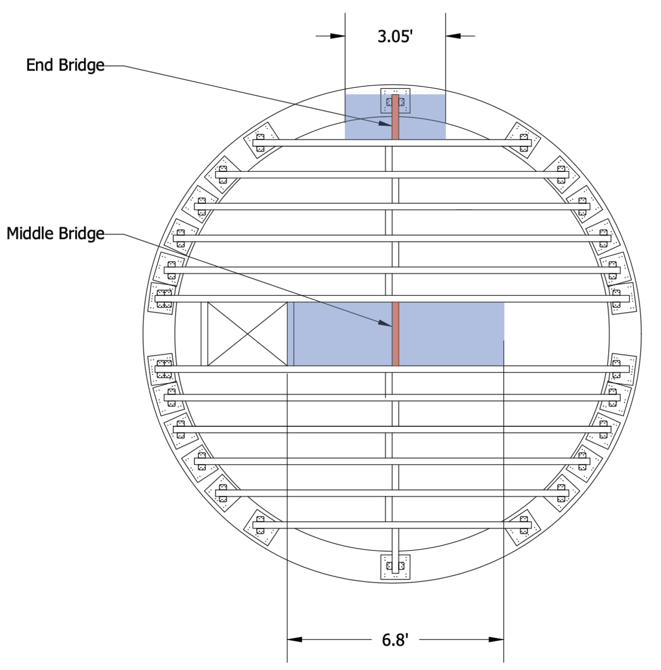
Dome Loft bridges with tributary widths – Click to open enlarged imaage
The capacity of the joist hangers was checked to verify that they can resist the maximum shear force experienced at the ends of the bridges, as shown below:

Earthbag Village Dome Loft | Joist Hangers Capacity – Click to open source spreadsheet.
3.1.3 CHECK FASTENER SPACING REQUIREMENTS ON THE BRIDGE
The end distance, edge distance, and spacing of the nails on the bridge were checked to prevent connection failure and ensure that the system performs as designed. The highlighted numbers in the spreadsheet are user-chosen, as shown below:

Earthbag Village Dome Loft | Joist Hangers Spacing – Click to open source spreadsheet.
Nail spacing was chosen based on the orientation of nails that the user would like on the plate. It is ideal to have properly spaced nails on all corners of the plates. We chose a value that is larger than the required spacing to satisfy the code requirement. We checked these important spacings for each fastener (nails in our case): to the end of the wood plate, to the edge of the wood plate, and between each adjacent nail, as shown below:

determining the location of joinery – Click to open the source page for this images a woodworking.stackexchange.com
3.1.4 CHECK FASTENER SPACING REQUIREMENTS ON THE BEAM
The end distance, edge distance, and spacing of the nails on the beam were checked to prevent connection failure and ensure that the system performs as designed, as summarized below:

Earthbag Village Dome Loft | Joist Hangers for the 3×10 Beams – Click to open source spreadsheet.
3.1.5 CHECK ROW TEAR-OUT FAILURE MODE ON THE BRIDGE
Fastener failure modes on the bridge were checked to ensure that the connection does not fail. Row tear-out failure occurs when the force imposed on fasteners in a row physically tears the row out through the end of the member; thus, breaking the connection. Row tear-out failure is based on the end distance of the fasteners, the amount of fasteners per row, the inter-row spacing of the fasteners, and the adjusted shear strength of the member. The check we completed is shown below:

Earthbag Village Dome Loft | Bridge Row Tear-Out Check – Click to open source spreadsheet.
3.1.6 CHECK ROW TEAR-OUT FAILURE MODE ON THE BEAM
Similarly, row tear-out failure was also checked for the beam, as shown here:

Earthbag Village Dome Loft | Beam Row Tear-Out Check – Click to open source spreadsheet.
BRIDGE-TO-BEAM ANGLE CONNECTION DESIGN SUMMARY
The Simpson LUS310 joist hangers manufactured by Simpson Strong-Tie were chosen to connect the bridges to the beams. The capacity of the joist hangers were verified to resist the maximum shear force experienced at the ends of the bridges. The end distance, edge distance, and spacing of the nails on the bridge, as well as on the beams were confirmed to prevent connection failure and ensure that the system performs as designed. Lastely, fastener failure modes on the bridge and beam were checked to ensure that connection failures are prevented.
3.2 BEAM-TO-PLATE CONNECTION
The next connection designed was the connection between the beam and bearing plate. The beam-to-plate connection serves the purpose of transferring the shear force from the end of the beam into the bearing plate for further load distribution into the walls. These seven steps were used to confirm that the product selection was appropriate for our application:
- 3.2.1 Select Product and Identify Relevant Properties
- 3.2.2 Check the Load Capacity of the Connection
- 3.2.3 Check Beam Fastener Spacing Requirements
- 3.2.4 Check Plate Fastener Spacing Requirements
- 3.2.5 Check Beam Tear-Out Failure Modes
- 3.2.6 Check Plate Tear-Out Failure Modes
- 3.2.7 Check Plate Capacity when Loaded at an Angle
3.2.1 SELECT PRODUCT AND IDENTIFY RELEVANT PROPERTIES
Again, a Simpson Strong Tie product with a published load table was used. Based on its load capacity, the Simpson A23, which is a 90 degree galvanized steel angle, was selected to connect beams to the bearing plates, as shown below:

The pertinent information for this produce was extracted and entered into the spreadsheet, as shown below:

Earthbag Village Dome Loft | Beam-to-Plate Angle Connection – Click to open source spreadsheet.
We were careful to note if the product load tables were specified for single angle connections or for back-to-back usage of angle connections. This information is typically stated within the published tables as a note. If it is not, contacting the manufacturer is imperative. It is crucial to ensure that the correct load capacity is used, because using a load capacity that is published for back-to-back angle connections on a design with only a single angle connection could cause the design to fail. We used published data for back-to-back angle connections.
3.2.2 CHECK THE LOAD CAPACITY OF THE CONNECTION
To check the adequacy of the connection, we identified the number of angle connections to use. The quantity of angle connections needed is the number of beams multiplied by the number of angle connections per beam plus the number of bridges connected to base plates multiplied by the number of angle connections per bridge. The specifics of our design is detailed as follows:
Angle Connection for Beams = (12 beams) x (4 angle connections/beam) = 48 angle connections
Angle connections for bridge ends = (2 bridge ends) x (2 angle connections/bridge end) = 4 angle connections
TOTAL angle connections = 48 + 4 = 52 angle connections
Therefore, 26 pair of angle connections.
We then took took the total shear at the level and divided it by the number of angle connections to know how much each is responsible for resisting. The connection was then verified by identifying if each angle connection has the capacity to resist the story shear demand per angle. The story shear demand also accounts for seismic loads. The resulting calculations are shown below:

Earthbag Village Dome Loft | Beam-Plate Connection Load Capacity – Click to open source spreadsheet.
3.2.3 CHECK BEAM FASTENER SPACING REQUIREMENTS
As was done for the joist hanger connection, the end distance, edge distance, and row spacing of the nails on the beam were checked to prevent connection failure and to ensure that the system performs as designed. The resulting calculations are shown below:

Earthbag Village Dome Loft | Beam Fastener Spacing – Click to open source spreadsheet.
3.2.4 CHECK PLATE FASTENER SPACING REQUIREMENTS
The end distance, edge distance, and row spacing of the nails on the plate were also checked to prevent connection failure and to ensure that the system performs as designed. The resulting calculations are shown below:

Village Dome Loft | Plate Fastener Spacing – Click to open source spreadsheet.
3.2.5 CHECK BEAM TEAR-OUT FAILURE MODES
Next, fastener failure modes were checked to ensure that the connection does not fail. Row tear-out failure occurs when the force imposed on the fasteners in a row physically tear the row out through the end of the member; thus, breaking the connection. Group tear-out occurs when a group of rows is physically torn out. Row and group tear-out must both be checked on the beam. The resulting calculations are shown below:

Earthbag Village Dome Loft | Beam Tear-Out Failure – Click to open source spreadsheet.
3.2.6 CHECK PLATE TEAR-OUT FAILURE MODES
Row tear-out failure mode was also checked on the plate. Since fasteners were placed in a group on the plate, group tear-out failure mode was also checked. The resulting calculations are shown below:

Earthbag Village Dome Loft | Plate Row Tear-Out Capacity – Click to open source spreadsheet.
3.2.7 CHECK PLATE CAPACITY WHEN LOADED AT AN ANGLE
The capacity of the plate was checked for when the loading is at an angle connection to the grain because the story shear may not perfectly align with the orientation of the plate grain around the perimeter of the dome wall. The resulting calculations are shown below:

Earthbag Village Dome Loft | Hakinson Formula for Plate – Click to open source spreadsheet.
BEAM-TO-PLATE ANGLE CONNECTION DESIGN SUMMARY
After verifying the strength of the Simpson A23 angle connection and the placement of fasteners on the base plate and beam, these dimensions of the angle connection were used to draw the side and plan view of the connection, as is shown in the image below
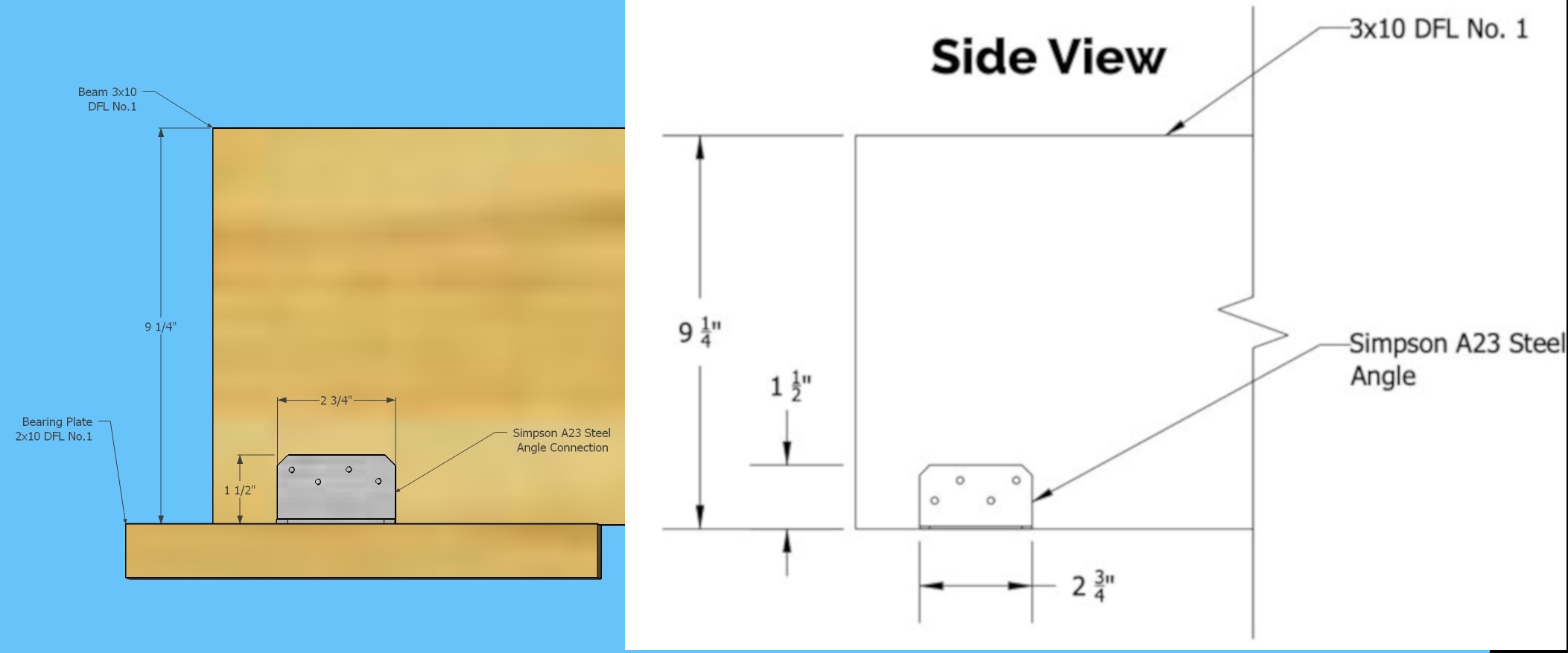
Beam-to-plate side view – Click to open enlarged image

Beam-to-plate Plan View – Click to open enlarged image
Looking down at the connection, in plan, the A23 angle connections extend 2” out perpendicular to the long edge of the beam and are placed 1 ½” away from the end of the beam. The length of the angle connections parallel to the long edge of the beam is 2 ¾”, which can be seen in both the plan and elevation views. The elevation view of the connection looks at the beam along the profile of its 9 ¼” height. From the elevation view, the height of the angle on the beam is shown to be 1 ½”.
The following image is applicable to all beams/bridges with the exception of the center two beams which will have double angle connections because of the additional strength needed, given the increase in beam spacing:

Other views of beam-to-plate – Click to open enlarged image
3.3 PLATE-TO-WALL CONNECTION
The last connection designed was the connection of the bearing plate to the wall. This connection transfers the load from the bearing plate to the wall. These seven steps were used to confirm that the product selection was appropriate for our application:
3.3.1 SELECT THE TYPE AND QUANTITY OF NAILS
In this design, we opted to use 20d common nails, which are the same as 4″ common nails, as shown below:

Common Nails Sizes Comparison Diagram – Click here to open full explanation at cnclathing.com
Using the ‘Nail Design Spreadsheet,’ we verified that the selected nail size was safe in compressive stress at the soil interface, in shear stress, and in deflection. The number of nails per plate was also determined, as shown below:

Earthbag Village Dome Loft| Nail Selection – Click to open source spreadsheet.
3.3.2 CHECK FASTENER SPACING REQUIREMENTS
As was done for the previous two connections, we checked the spacing of the fasteners on the member. The requirements for the fastener spacing on the plate in this connection are the same as those identified in the beam-to-plate angle connection for loading parallel to the grain on the plate. The resulting calculations are shown below:

Earthbag Village Dome Loft| Nail Spacing – Click to open source spreadsheet.
3.3.3 CHECK FASTENER WITHDRAWAL RESISTANCE
The nails on the plate were also checked for their withdrawal resistance. Withdrawal resistance of the fasteners is their capacity to resist being pulled out of the bearing plate. The withdrawal demand stems from the shear force at the end of the beams. The resulting calculations are shown below:

Earthbag Village Dome Loft | Nails Withdrawal Resistance – Click to open source spreadsheet.
3.3.4 IDENTIFY FASTENER EMBEDMENT LENGTHS
The ‘Nail Design Spreadsheet’ was used to determine the embedment of the fasteners into the earthbag layer above and layer below the connection. The width of the bearing plate was accounted for when determining the embedment lengths, and the nails are designed to embed equally into each adjacent layer. The resulting calculations are shown below:

Earthbag Village Dome Loft | Fastener Embedment – Click to open source spreadsheet.
3.3.5 CHECK PLATE NET TENSION CAPACITY
As an additional check, we confirmed that the plate’s net tension resistance is greater than the tension loads that may be imposed from the story shear. It was important to check the capacity of the plate in tension because timber as a structural material is stronger in compression than it is in tension. The resulting calculations are shown below:

Earthbag Village Dome Loft | Plate Net Tension Check – Click to open source spreadsheet.
3.3.6 CHECK PLATE TEAR-OUT FAILURE MODE
Finally, we checked for row tear-out failure mode of the nails on the plate. This failure mode occurs when the force imposed on fasteners in a row physically tears the row out through the end of the member; thus, breaking the connection. The resulting calculations are shown below:

Earthbag Village Dome Loft | Plate Row Tear-Out – Click to open source spreadsheet.
PLATE-TO-WALL CONNECTION DESIGN SUMMARY
The plate-to-wall connection design consists of 20d common nails placed at various locations on the base plate, in groups of 1” spaced nails. The following four images are the four different variations of nailed plate designs around the perimeter of the dome. Different variations were needed to maintain the 6” bearing length and have the nails adequately spaced around the plate as they follow the curve of the perimeter, as shown here:


The use of double angle connections was needed on the two central beams where the shear force at the beam ends is higher. The forces are higher there because the tributary length (distance between the beams) is greater than 1′, as is the case for the rest of the beams.
PART 4 – DECKING
The final step in designing the structural layout of the loft was to verify the capacity of the deck material and thickness to resist the design loads. We created a tab for this design component within the Earthbag Village Loft Design Calculations Spreadsheet called the Decking tab. These 5 steps were used to confirm that the product selection was appropriate for our application:
- 4.1 Specify Material Properties
- 4.2 Determine the Bending Strength
- 4.3 Determine the In-Plane Shear Strength
- 4.4 Determine the Deflection Strength
- 4.5 Verify that Strength and Deflection are Satisfactory
4.1 SPECIFY MATERIAL PROPERTIES
A manufactured deck product was used because they come with published load tables. PSF-TECO sheathing was selected for this design. More specifically, Oriented Strand Board (OSB) plywood with a sheathing span rating of 48/24 was selected. The first number in the sheathing span rating is the maximum on-center support spacing, in inches, when the panels are used for roof sheathing, and the second number is the maximum on-center support spacing when used for subflooring. The second number is applicable for this design. All relevant properties of the selected deck material were noted in the spreadsheet, as shown here:
 Desingn Table")
Earthbag Village Dome Loft | Oriented Strand Board (OBS) Design – Click to open source spreadsheet.
4.2 DETERMINE THE BENDING STRENGTH
According to the supplier (PFS-TECO), the sheathing in this design is considered three-span because the sheathing supports are spaced less than 32 inches on-center. The bending capacity of the sheathing panels was found on the associated PFS-TECO technical data sheet. The allowable uniform load on the three-span sheathing panels given its bending capacity was calculated using the following formula: wb = (120M) / (Lb)2, as shown here:

Earthbag Village Dome Loft | OBS Bending Strength – Click to open source spreadsheet.
4.3 DETERMINE IN-PLANE SHEAR STRENGTH
The in-plane shear strength of the decking was calculated to determine the associated allowable load for the panels. The in-plane shear strength capacity was found on the PFS-TECO technical data sheet. The allowable uniform load of the three-span sheathing based on its shear strength was calculated using the following formula: ws = (20Vs) / Ls, as shown here:

Earthbag Village Dome Loft | OBS Planar Shear Strength – Click to open source spreadsheet
4.4 DETERMINE THE DEFLECTION STRENGTH
Finally, the allowable uniform load on the three-span panel under deflection criteria was verified. The EI of the selected flooring material was found in the published technical data sheets, and is the quotient of the material’s modulus of elasticity (E) and moment of inertia (I). These properties dictate the magnitude at which the panels deflect. The resulting calculations are shown below:

One Community’s Earthbag Village Dome Loft | Deflection Table – Click to open google spreadsheet.
4.5 VERIFY THAT STRENGTH AND DEFLECTION ARE SATISFIED
We then identified the lowest allowable load on the structure. In other words, the maximum load that could cause the loft to bend to a point of failure. We looked at the following allowable loads calculated from each design criteria (bending, shear, and deflection):
Bending allowable load = 83.5 psf (pounds per square foot)
Shear allowable load = 231 psf
Deflection allowable load = 84.6 psf
83.5 psf is the max load that can be on the loft before it will fail in bending. Therefore, the minimum allowable total load is governed by bending strength. So, we verified that this bending strength was larger than the governing design load from the ASCE 7-16 load combinations determined previously in Section 1.3 Identify The Governing Load Combo. The panel design strength purely under live load was also checked and it was determined that the panels can safely resist the design live load, as shown below:

Earthbag Village Dome Loft | OBS Decking Checks – Click to open source spreadsheet.
DECKING DESIGN SUMMARY
The deck design consists of 48/24-rated ¾” thick 4×8’ OSB panels, as shown here:

(AAA TTT may need to replace this one too after Hannah double checks)
Five panels will be needed per dome to fit the loft area, as shown in the image below:
Here is an example of the minimal number of panels needed and how to cut them:

The panel layout may be different for every dome, because of slight differences in the building process. For each dome, measurements need to be taken on site based on the specifics of how that particular dome turned out. The resulting design uses 8d common nails to fasten the decking to the structural system with a spacing of 6” on-center along each beam and bridge. To place boards correctly and avoid buckling, watch the following video:
Counterweights aren’t usually needed during earthbag construction because the overlap is big enough for the bags to not fall inward, and using one continuous bag forms a circle that additionally supports itself from inward collapse. Using individual bags is less stable but still doesn’t usually need counterweights.
Note: Counterweights will be needed though on the exterior of the dome during construction if aircrete is used instead of earthbags. When using aircrete, the final loft design stability requires the complete dome.
For maximum safety, people shouldn’t be walking on or using the loft platform until the dome is complete, because the dome is not maximally self-supporting until the arch is completed at the top. We do not advise people (even a couple) to stand on the loft until several feet of earthbag have been placed on the earthbag wall above the level of the loft. Although the nails will not withdraw out of the wood plate, the soil that we fill the poly bags with is more variable in nature depending on the mix and proper tamping.
During construction, the bearing plates will be placed first, then the deck joists, followed by nailing OSB decking to the joists when the entire dome wall is complete. The bearing plates will be secured by the weight of the next poly tube bag layer above it. Tamping it in place will embed the nails into it before the internal mix hardens. For added support, we’ll make the earthbag layer on top of the bearing plates the same thickness as the loft.
The decking is designed to start outsideinside the wall to allow the layer above to be tamped into place in between the joists. This method also allows the deck to be nailed to the joists later on, thus reducing the chance of people walking on the loft frame prematurely. Individual bags can be placed in between and around the joists in addition to the tube bag if needed.
FINAL LOFT DESIGN
The image below encompassess the final structural system of the loft design. The beams and bridges are 3×10 DFL No. 1; they are connected by Simpson LUS310 joist hangers. The beams and bridges are connected to the 2×10 DFL No. 1 base plates with Simpson A23 angle connections, and the base plates connect the structural loft system to the dome wall with a series of 20d common nails.
(AAA – may need to replace this one too after Hannah double checks – loft entrance may be in different place now?)

RESOURCES
- Book: “The ASCE 7-16”
- Article: “Simply supported beam diagrams : article | calcresource”
- Wikipedia: “Beam (structure)”
- Video: “Prevent Buckling with Proper Spacing – APA Builder Tips”
- Video: “Sub-floor Installation Tips from Georgia-Pacific”
FREQUENTLY ANSWERED QUESTIONS
Q: Is this guide complete?
No. We do not consider this guide complete yet. This design is not sufficient to build even our own structures until we’ve received a stamp on the final plans from an engineer licensed in the state we’ll be building in, as well as completing our own construction of the first unit. We’ll share those stamped plans here when we have them. We will also share anything new we learn during the approval and construction process.
![]()


Connect with One Community