 One Community
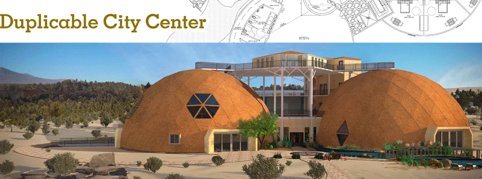
Duplicable City Center Dome-Hub Connector Engineering
This page shares the research and design methods used by the team to ensure the safety and manufacturability of the Duplicable City Center Dome Hub Connectors. For easy reference, the document is divided into the following sections:
- Related Pages
- What are City Center Dome Hub Connectors
- Why Open Source
- Ways to Contribute and Researchers
- Traditional Geodesic Dome vs. City Center Dome
- Hub Connectors Design Considerations
- Design Summary of Findings
- Next Needed Steps
- Load Calculation of the Entire Dome
- Cost Analysis (Manufacturer vs DIY)
- Resources
- Summary
- Frequently Answered Questions
NOTE: THIS PAGE IS NOT CONSIDERED BY US TO BE A COMPLETE AND USABLE TUTORIAL UNTIL
WE HAVE OUR PLANS PERMITTED AND HAVE COMPLETED THE CONSTRUCTION OF THE DUPLICABLE CITY CENTER®.
AT THAT TIME WE WILL ADD HERE THOSE PERMITTED PLANS AND ANYTHING ELSE WE LEARNED.
IN THE MEANTIME, WE WELCOME YOUR INPUT AND FEEDBACK
RELATED PAGES

")
")
")
")
")
")
")
WHAT ARE CITY CENTER DOME HUB CONNECTORS
 One Community is designing an open source Duplicable City Center to model a redefinition of how people can live more sustainably, efficiently, and meaningfully. The Duplicable City Center consists of a cluster of 3 geodesic domes. Geodesic domes were chosen for a broad diversity of reasons: (1) they are uniquely attractive; (2) they provide large open spaces, (3) the curved walls and ceiling use approximately a third less surface area to enclose the same volume as a traditional box home; (4) they perform well with heating and cooling because the aerodynamics of the rounded walls encourage air to travel around efficiently inside the building and (5) they are structurally beneficial because the round structures weather hurricanes and tornadoes significantly better than box structures.


Geodesic Domes are sphere-like structures consisting of a network of triangles which provide a self-balancing structural framework that uses minimal materials. The structural analysis of the dome is essential for determining the effects of loads and forces on the structure. This project completes the structural analysis by analyzing the hub connector of the geodesic dome. The beams intersect in a star shape and need to be connected, as shown in the image above. These connection points are called hubs. The goal is to design an economical DIY replicable hub connector that is made of readily available materials and without complex equipment or custom tooling for the Social Dome, Dining Dome, and Living Dome that make up the Duplicable City Center.
BACKGROUND ON GEODESIC DOMES
Unlike traditional geodesic domes, where the triangles are not neatly organized in equal height rows, the City Center domes are comprised of rings of triangles that elevate each row of the structure uniformly around the circumference, illustrated below. This design was chosen to reduce complexity of building the structure.

Illustrations Showing Traditional Geodesic Dome and One Community’s Modified Domes
The table below shows triangle dimensions of the first 5 rows of the dome. The last column is the height of the triangle showing the equal height of each row.

Table Showing the Equal Height of Each Row – Click for source spreadsheet
It can be seen in the dome images above how the dome is designed to have equal row height. This equality of the triangles will allow for better stress distribution and as discussed below, how the triangle height affects the stresses in the beams, having uniform long triangles will make it so that we will have less stress in the dome design. As seen in the table above, this will be accomplished using isosceles triangles, which are triangles with 2 sides of equal length, and this is what will create the equal height of the first few rows. As the rows increase towards the middle of the dome, a transition is made to scalene triangles, which are triangles that have sides of 3 different lengths. However, as seen in the table, the height of the row will remain equal regardless of what kind of triangle is being used.
SCIENCE OF GEODESIC DOMES
Here is the science behind traditional geodesic domes, which are structures based on a very simple phenomenon. Geodesic domes rely on the strength of a triangle to implement rigidity in the structure. Once you understand how a triangle distributes its stresses, you can understand how a geodesic dome also distributes its stresses. Geodesic domes can be designed differently depending on the size of the dome. All geodesic domes are based on the icosahedron. The icosahedron is a geometric solid that has 20 sides, called faces, and each face of the icosahedron is made from an equilateral triangle. The dome we are building is a 4V dome, meaning this dome has a frequency of 4. This means that each edge of the icosahedron has 4 surfaces and 3 vertices that are pushed out. Each face of the icosahedron will now be pushed outwards from a flat face to a more rounded shape. Below is an illustration of how each equilateral triangle on the face of the icosahedron is transformed into an arc, giving the dome its spherical shape.

Equilateral Triangles on an Icosahedron Creating the Spherical Shape.
Figure 1 shows an icosahedron, and Figure 2 illustrates this icosahedron projected over the dome, showing how it is transformed into a spherical shape on the dome (shown below).

Figure 1: Illustration Showing an Icosahedron

Figure 2: Projection of an Icosahedron on a Geodesic Dome
There are 16 smaller triangles within one face of this icosahedron. If this is hard to visualize, imagine taking a flat sheet of circular paper and cutting a slit in it to make it into a cone. This can be seen in the gif below (Figure 3), demonstrating a flat sheet of paper (2D) being turned into a cone (3D). Hopefully, this helps in visualizing how a 2D object is being transformed into a 3D object.

Figure 3: a Video Showing How a Flat Circle is Turned Into a Cone
The greater the frequency of the dome, the higher the number of triangles and the more spherical the dome will be. The frequency also determines the size and strength of the dome. The best connector/strut length for the geodesic dome should be around 5 ft. Once struts exceed 5ft there is increased buckling in the struts and they can fail. More information on the correlation between strut lengths and frequency can be found here. To make larger domes, the strut length is not increased but rather the dome frequency is increased. Regardless of its size or frequency, every geodesic dome has only six 5-way hub connections and all others will be 6-way hub connections. One of these six 5-way hub connections is located at the top of the dome while the other five are evenly spaced around the dome. The number of struts between each of these 5-way hub connections will tell you the frequency of the dome. This means we would have to find a pentagon (highlighted in red in Figure 2) on the dome and start counting the number of struts from one pentagon to the next. For example, the struts highlighted in blue in Figure 2 converge at the centers of all the pentagons found around the dome. It can be seen that there are four struts from the center of each adjacent pentagon, identifying this as a 4v dome.
Now that the geometry of the geodesic dome is understood, it can be seen why this design is superior to regular structures and how these triangles distribute stress around the dome. Below we can see how stress is distributed in a triangular beam structure. The red beams are in compression (a compressive force is one that squeezes something). The blue beams are in tension (a tension force is one that stretches something).
Figure 4 is an illustration showing the stress distribution of an equilateral triangle, which is a triangle with three sides of equal length and three interior angles of equal degrees. This figure pictures an equilateral triangle with a compressive force of 50lbs and compressive stress of 29lbs. Since an equilateral triangle is symmetrical, the reaction forces will be equally distributed between the bottom nodes as 25lbs, half of the compressive force at the top node.

Figure 4: An Illustration Showing the Stress Distribution of an Equilateral Triangle
Once these three reaction forces are known, equilibrium equations can be applied to any node to find the tensile and compressive stress. The node diagram below shows how to set this up. The below equations show the compressive and tensile stresses that are produced, -28.86lbs is FAC which is compressive stress and 14.43lbs is FAB which is tensile stress. The sign convention tells us that negative stress will be compression and positive stress will be tension. These figures change drastically when the type of triangle changes.

The above example utilized an equilateral triangle, with equal angles at all intersections. The next example will show what happens when this triangle is flattened, which is how triangles at the top of the dome will be. Figure 5 (below) is an illustration showing the stress distribution for a short, non-uniform triangle typically found at the top of the dome.
This triangle behaves similarly to the previous one but now has drastically higher stresses. We can see that the compressive stress is 100lbs which is double the force applied. The tensile stress is 97lbs, which is also higher. This demonstrates how the angle affects the stresses in the beams. The same equations used for the equilateral triangle can be applied to calculate these stresses when the angles are known. This is useful in the design stage for seeing whether the beams will be able to handle this stress.

Figure 5: An Illustration Showing Stress Distribution for a Short Non-uniform Triangle
In the two pictures below, it is easy to see which struts are in tension (blue) and which ones are in compression (red). There are rings of tension that go around the entire dome and there is compression in the struts in between these rings. A load at one node will trigger the effect seen in the left figure below, however, the shape of the dome allows the distribution of this load to multiple nodes. Therefore, in the case of a snowstorm, the weight of the snow will not be concentrated on one node but will rather be distributed over a larger cross-section. This means if the weight of snow on the top of the dome is 100lbs, it will be distributed along a number of nodes. If distributed among 12 nodes, for example, this 100lbs will be divided by 12 to give a resultant of 8.3lbs of snow at each node. This causes there to be much less stress on the beams. This same concept also applies to wind. At any angle that wind hits the dome, there will be multiple nodes taking the stress of the wind force, allowing for the structure to handle a greater wind force than a traditional building. To learn more about the structural analysis of the domes check out this article by geo-dome, or watch their insightful video.

Figure 6: Concentrated Load at the Top

Figure 7: Distributed Load at the Top
Now that the geometry of the dome is better understood, aligning different lengths of beams to construct the dome can be simplified. Not all struts can be the same length as they would not be able to connect together to form this dome shape. The general rule of thumb is that the struts in the middle need to be longer than the outside struts. This feature of the geodesic dome is illustrated below.

Figure 8: Traditional 4v Geodesic Dome

Figure 9: Strut Configuration of a 4v Dome
There will be 6 different strut lengths which will build up one “2D face” of the equilateral triangle of the icosahedron (Figure 1). As mentioned above, the lengths of A and F will be shorter than the lengths of struts B, C, D, and E. There are multiple calculators on the internet that will give you the lengths of these domes, the calculator used for this was on the website of zip tie domes. For a 30 feet diameter dome the dimensions of the struts will be Red (A): 3ft 10.75 in; Yellow (B): 4ft 6.5in; Brown (C): 4ft 6.375in; Black (D): 4ft 9.75in; Blue (E): 5ft; Orange (F): 4ft 7.5in. This dome would be 15 feet high. Depending on the requirements, the calculations can be adjusted to get different strut sizes. For any 4V dome, we require 30 Red “A” struts, 30 Yellow “B” Struts, 60 Brown “C” Struts, 70 Black “D” Struts, 30 Blue “E” Struts, and 30 Orange “F” Struts. To see more dimensions on this specific diameter dome you can click here. Everything explained up to this point is the traditional way to build a 4V dome.
WHY OPEN SOURCE
Open sourcing the hub connector design research is important so that other engineers/designers can use this research to improve on the design and/or use it in their projects. As far as hub connectors go, there are a few designs out there that are very bulky. Therefore, creating this document will allow people to replicate our efficient design and build upon it. Our hope in sharing what we’ve learned is to increase structural stability and reduce the cost of future geodesic domes.
WAYS TO CONTRIBUTE AND RESEARCHERS
SUGGESTIONS | CONSULTING | MEMBERSHIP | OTHER OPTIONS
CLICK THESE ICONS TO JOIN US THROUGH SOCIAL MEDIA
![]()
![]()
![]()
![]()
![]()
![]()
![]()
![]()
![]()
![]()
RESEARCHERS FOR THIS COMPONENT:
Ayushman Dutta: Mechanical Engineer
Charles Gooley: Web Designer
George Koshy: Design Engineer
Julia Meaney: Web and Content Reviewer and Editor
Justin Varghese: Mechanical Engineer
Julio Marín Bustillos: Mechanical Engineer
Koushik Chandra Katta: Mechanical Engineer
Nikhil Bharadwaj: Mechanical Engineer
Nupur Uresh Shah: Mechanical Engineer
Prathik Jain: Mechanical Engineer
Raj Patel: Mechanical Engineer
Shu-Tsun Huang: Engineer
Srujan Pandya: Mechanical Engineer
Sunitha Paraselli: Mechanical Design Engineer
Tasmia Hasan: Design Engineer
TRADITIONAL GEODESIC DOME VS. CITY CENTER DOME
COMPARATIVE ANALYSIS INTRODUCTION
One Community has developed a tailored dome design for the Duplicated City Center, drawing inspiration from the traditional geodesic dome. The core objective of this pioneering project is to streamline production complexity and curtail material costs. In this report, our focus centers on an in-depth examination of the new model’s performance, achieved through a meticulous analysis of its load capabilities utilizing finite element analysis (FEA)*. By conducting a comparative study between the two models, we comprehensively evaluate the effectiveness of the modified design.
*Note: FEA serves as a powerful tool in simulating the behavior of components under specific conditions, thereby reducing the necessity for physical prototypes and enabling seamless component optimization throughout the project’s design process.
FRAME MODELS
In order to expedite the analysis of the two models, the mechanical engineering team has made a strategic decision to employ frame models for testing the structures, as opposed to designing full-size beams and hub connectors. This approach not only saves valuable time and resources but also allows for a more efficient evaluation of the models. Leveraging the frame analysis function in Inventor software, the team can accurately assess the performance and structural integrity of the frame models, providing crucial insights for the overall assessment of the designs.

Figure 1: Traditional Dome Frame Model

Figure 2: City Center Dome Frame Model
Here are the “Traditional Dome vs. City Center Dome Structural Engineering Loading Comparison Report” files used.
VERTICAL LOADS
The vertical load tests were conducted to assess the gravity load capabilities of the two models. Prior research indicated that the combined gravity load of the City Center domes, accounting for beams, connectors, and both inside and outside surface areas, amounted to 62645.9 lbs.
Using the calculated total weight, the team uniformly applied loads to the hub connector nodes of each model from the top side. As shown in Figure 3, the City Center model exhibited significantly superior performance compared to the traditional model. Specifically, the City Center model demonstrated a maximum displacement of 0.08875 inches, while the traditional model recorded a maximum displacement of 0.2122 inches. Subsequent tests distributed the load to the second and third layers, and though the differences were decreased as the test moved down the layers, the City Center model still exhibited smaller maximum displacements. Based on these results, we confidently conclude that the City Center dome boasts superior vertical load capability over the traditional model.

Figure 3: Vertical Load Test Results
During the vertical load test on the models, the bottom layers were meticulously pinned from all angles to accurately simulate the real-world effect of building on a foundation. In order to ensure a comprehensive assessment, all loads within the same model were evenly distributed, effectively sharing the weight uniformly in the vertical direction. This approach allowed us to capture the most realistic and representative behavior of the structures under vertical loading conditions, aiding in a thorough and reliable evaluation of their performance.
WEATHER & ENVIRONMENTAL EFFECTS TESTS
To ensure the structural viability of One Community’s Duplicated City Center across diverse global locations, an extensive research initiative was undertaken to investigate the impact of varying weather conditions and environmental factors, encompassing wind loads, snow loads, and earthquake loads. These investigations were paramount to gaining comprehensive insights into the structures’ performance.
WIND LOADS
While wind naturally exerts force on the entire building surface in real-life scenarios, our study utilized simplified models focusing solely on the frames. The mechanical team opted to assess the effect of wind on a group of vertical beams, subjecting them to continuous perpendicular loads.
As depicted in Figures 3 & 4, noteworthy findings emerged. The City Center dome model exhibited maximum displacements that were consistently 10% lower than those of the traditional dome model. Interestingly, despite this advantage, the total loads experienced by the City Center dome were only marginally 2% lower than those of the traditional model. Based on these outcomes, it is evident that the City Center dome boasts superior wind load capability in the horizontal direction, which reinforces its resilience and suitability for diverse weather conditions worldwide.

Figure 4: Wind Load Test – Traditional Model

Figure 5: Wind Load Test – City Center Model
In our pursuit of comprehending the impacts of side-applied forces on the models, we deliberately applied continuous loads that exceeded real-world scenarios significantly. Thorough research and calculations revealed that the magnitude of the applied continuous load, set at 50 lbf/in, would be equivalent to an astonishing wind speed of 1675 mph. While this deliberate exaggeration was employed for analytical purposes, it provided valuable insights into the structural responses and performance under extreme conditions. By subjecting the models to such intense loads, we gained crucial knowledge about their behavior, enabling us to better evaluate their resilience and safety argins when subjected to more realistic forces in real-world applications.
SNOW LOADS
In anticipation of snowy conditions at the site of the Duplicable City Center when constructed in cold areas, this section of our report focuses on evaluating the impact of snow-induced gravity on the structure, specifically the geodesic dome. The dome’s unique design generally prevents significant snow buildup, as wind easily removes thin layers of accumulated snow. However, to thoroughly assess the dome’s snow load-bearing capability, we conducted comprehensive tests.
To simulate the additional building load caused by snow, we identified the gravity parameter as a critical factor in the structure’s model. By adjusting this parameter, we sought to understand how the dome would respond to varying snow thicknesses in different regions. In our testing process, we considered gravity accelerations of both double and four times the standard value to assess the dome’s resilience under different snow conditions.
Figure 6 presents the results of the snow load tests for both models, indicating minimal differences. As previously mentioned, the dome’s unique design facilitates the removal of snow by wind. Even in extreme ice storms where snow buildup occurs, the dome only experienced a displacement of 0.06 inches under a weight equivalent to three times its self-weight (180 lbs). Considering the surface area of 7558 ft2, this snow load could accumulate up to 2 ft of settled snow, but such extreme conditions are rare and would not cover the entire dome structure. This displacement is well within the building’s dead load rating.
Additionally, we observed that the City Center dome’s beam volume was slightly larger than that of the traditional dome model, indicating an approximate 5% increase. This suggests that the City Center dome exhibits slightly better snow load-bearing capability compared to the traditional dome.

Figure 6: Snow Load Test Results
Overall, the test results demonstrate the dome’s ability to withstand potential snow-induced stresses and its overall resilience in cold environments. These findings provide valuable insights for ensuring the structural integrity and safety of the Duplicable City Center in snowy conditions.
EARTHQUAKE LOADS
In regions like California, earthquakes pose significant safety hazards as a consequence of natural environmental factors, demanding careful consideration in structural design. The irregular and unpredictable nature of earthquake activity makes it challenging to fully simulate through software. To address this, we utilized a unidirectional continuous load on the bottom beams as a means of simulating movement.
Figure 7 provides insights into the results. When a 5 lbf/in continuous load was applied to the bottom layer beams, the City Center model exhibited a maximum displacement of 21.13 inches, while the traditional model recorded a significantly higher maximum displacement of 30.15 inches – almost 50% more than that of the City Center model. Even with a continuous load increase to 50 lbf/in, the traditional dome model still remained 35% higher in maximum displacement compared to the City Center model.

Figure 7: Earthquake Load Test Results
Based on these compelling findings, we conclude that the City Center dome excels in earthquake load capability. Its superior performance in withstanding seismic forces further reinforces its viability as a safer choice for structures located in earthquake-prone regions like California.
GEODESIC DOME CONCLUSION
In comparison to the traditional geodesic dome model, the City Center dome model exhibited varying degrees of improvement in load capabilities across different external conditions:
- Vertical loads improvement: 9.87%
- Wind loads improvement: 25.07%
- Snow loads improvement: 3.44%
- Earthquake loads improvement: 25.39%
These compelling findings solidified the City Center dome’s position as the more convincing and preferable choice of dome design in terms of safety considerations. The comprehensive enhancements observed in its performance under diverse environmental forces and load scenarios provide strong evidence of its superior structural integrity and reliability. As a result, the City Center dome emerges as a highly reliable and secure option, offering enhanced safety features for its intended application.
FUTURE CONSIDERATIONS
Throughout this research, we have diligently examined four distinct cases of load conditions, each contributing valuable insights into the structural behavior of large buildings. However, it is essential to acknowledge that the potential for further exploration is vast, as numerous other load scenarios warrant investigation. As a result, this study lays a robust foundation for future expansion and augmentation. Expanding the scope of this research in the future has the potential to yield even more comprehensive and nuanced findings, providing an even deeper understanding of the structural dynamics and performance of large buildings under diverse and challenging conditions. By continually refining and broadening the scope of this research, we can strive to enhance the safety, efficiency, and reliability of architectural structures in the years to come.
HUB CONNECTORS DESIGN CONSIDERATION
In this Section, our engineering findings and the process we used to reach these results will be discussed, as well as the various designs and simulations that were done over the duration of the design stage. All the proposed plans need to be checked and signed off by a state-licensed engineer before construction can begin. The areas covered in this section are:
- Design Summary
- Designs Considered
- Design Summary of Findings
- Next Needed Steps
- Load Calculation of the Entire Dome
- Cost Analysis (Manufacturer vs DIY)
- Resources
- Summary
- Frequently Answered Questions
DESIGN SUMMARY
With any custom design, there are unique problems and unique ways of dealing with these problems. We have developed multiple designs of the hub connector and each has had its flaws. Our design has evolved through various iterations into a hub connector that meets all of our criteria. The steps taken to reach our final design are as follows:
STEP 1
The first step in any design process is to define the task at hand and identify the constraints one has to work with. In this case, the task is to design a connector for the geodesic dome using “v” shaped brackets, eliminating the center portion that is in most off-the-shelf hub connectors. The challenge that comes with this is maintaining the structural strength while reducing the allowable deflection the structure goes through under full loading conditions. The design constraints were as follows:
- The design should be based on the 12 X 2 LVL beams.
- The design should be easily replicable without any complex equipment or custom tooling.
- The design should use readily available materials such as Stainless steel, Galvanized steel, or Aluminum.
- Easy to attach to beams.
- Load assumptions are that the bracket needs to withstand a force of 1732 lbf.
STEP 2
The next step is to come up with a design that meets all criteria and run the finite element analysis on this first design. After that has been completed, the failure points are determined and the design will be updated to reinforce it for improvement. Finite Element Analysis (FEA) is a method in which we analyze the material properties of a metal, the geometry of the part, boundary conditions (fixtures to ensure the part is fully constrained), and forces that we want to analyze the part (in this case our hub connector) for. The part is then broken into multiple nodes and uses numerous differential equations to find out the stress and displacement occurring in different regions of this part. In the era of technology, this is very easy as we can use most CAD (Computer Aided Design) software to do this. To a layman, these charts produced by CAD software are easy to read. In the SolidWorks-generated charts used in this document, we have both stress and displacement analysis, the color codes are the same for both curves. To learn more about interpreting FEA results check out this webpage by enterfea. The colors represent the following:![]()
- Red represents Maximum Values.
- Orange represents values approaching maximum.
- Yellow represents values that are greater than the middle, but not close to the maximum.
- Greens represent values in the middle of the minimum and maximum.
- Blues represent Minimum Values.
STEP 3
Once a design is made that meets all the criteria, a cost analysis needs to be done to determine whether it is justified to manufacture this design. Once the cost analysis step is complete, a licensed engineer should review the schematics of the design to approve it or recommend any necessary changes that need to be made. Once the design is approved it is ready for construction.
DESIGNS CONSIDERED
In this section, we will discuss the designs chosen, how they failed, and most importantly what we learned from the failures in order to come up with the next iterations of the design which fit the criteria of the project. The designs were all made very thoughtfully by the team using various online resources for researching the best approach to meet the given criteria. The team chose to use stainless steel because stainless steel types 304 and 316 have proven their compatibility to work as brackets and fasteners on wood connections, according to this article. Since the brackets need to be a DIY option, having too thick of metal would require more expensive equipment for bending. Therefore, it was decided that stainless steel of 0.18-inch thickness would meet the design criteria. Although any structural grade steel can be used as long it has similar strength, different steel choices can be made depending on factors such as cost or availability of the material. Aluminum is not recommended since it is much weaker than steel. The designs seen in this section were analyzed using stainless steel 316.

CITY CENTER HUB CONNECTOR DESIGN 1
Multiple smaller brackets to distribute the force and the moments. In this approach, the brackets were designed using a 7-gauge Stainless sheet (0.18″ thickness):
In our first design, we chose the stainless steel material because of its great strength. The thickness chosen was 0.18-inch (7 gauge) since this is the thickest material that can be bent using DIY methods. The attempt was to distribute the load of 1735.8 lbf across the 4 brackets (as seen below in Figure 12) and to reduce the moments on the top and side connectors of the geodesic dome caused by the weight of the beams and the interior attached to the beams. Moments are the tendencies of a force to rotate a body, or “twisting forces” that cause angular accelerations. This distributed the seismic loads across the 4 brackets, with each bracket being subjected to a force of 433.95 lbf.

Figure. 12: Assembly Showing the V Bracket of Design 1
The simulation was done by placing fixtures on one side of the bracket and loading the other side, as shown in figure 13 below. The FEA showed the brackets had failed the load test. The maximum force recorded was 530 MPa at the joints when the yield strength was 172.4 MPa. When the test was done with loads applied on both sides of the bracket, the maximum load was higher at 1075 MPa.

Figure. 13: Compression Analysis of Design 1
FEA was done on the assembly as seen in Figure 14. The end of the laminated veneer lumber (LVL) beams were fixed and the load was 867.9lbs. Half of the total force the beams can hold, as it was attached on two sides, was applied to the front face of the beams. The assembly was analyzed for deflection and to understand the points of maximum stress. Figure 15 shows the deflection of the assembly under the load. This is not the actual behavior of the systems as the LVL beams don’t have this extent of plasticity (the ability of a material to remain in its new form after being changed by various forces and pressures). Because of this, the beam would have potentially cracked at various layers before this amount of deflection. Detailed analysis was required to show the nonlinear behavior. A large displacement test was done on the assembly but due to limits in computation, the test failed after 5 hours.

Figure 14: Boundary Conditions of Design 1

Figure 15: Displacement Analysis of Design 1
However, the brackets showed a stress value of 1484 MPa at this level of deflection, which is higher than the yield strength of stainless steel (172 MPa). But given the linear behavior of the test, it was difficult to determine the point of failure. This design showed many failure points (see figure 16 below) so we chose to stop considering it and moved on to other ideas.

Figure 16: Stress Analysis of Design 1
CITY CENTER HUB CONNECTOR DESIGN 2
A single large bracket. In this approach, the brackets were designed using a 7-gauge Stainless sheet (0.18″ thickness):
Our next design (seen in Figure 17) improved the previous design to be a single bracket with a larger surface area, therefore increasing the quantity of material available for the load distribution and reducing the stress. This approach proved to be better as FEA indicated reduced stress in the brackets. The load applied on the brackets was 867.9 lbf as a single LVL beam was held by two brackets.

Figure 17: Assembly Showing the V Bracket of Design 2
The simulation was done by placing fixtures on one side of the bracket and loading the other side, as shown in Figure 18. The FEA showed the bracket failed the load test. The maximum force recorded was 376.8 MPa at the joints when the yield strength was 172.4 MPa. When the test was repeated with loads applied on both sides of the bracket the maximum load was higher, at 379.4 MPa. The FEA was done in a similar method to the previous assembly. The mesh was refined to accommodate tight tolerances in threading. A load of 867.9lbs was applied to the front face of the LVL beam. The displacement and stress were then analyzed.

Figure 18: Compression Analysis of Design 2

Mesh Density Visualization – Click for source
Figure 19 is the result of a linear analysis that shows the potential displacement of the LVL beams under plastic conditions. This behavior was not fully accurate as the model analyzes the beam as a singular piece but it actually consists of many plies laminated together. Therefore, in reality, the beams would fail differently than is modeled. Regardless, this analysis showed the lack of rigidity in the design using just “V” brackets. Figure 20 shows the stress the assembly endured under fully loaded conditions. The maximum stress in the bracket was higher than the yield strength of the stainless steel sheet. The maximum stress at this exaggerated displacement simulation was 1399 MPa. This is the reason this design was considered a failure, leading us to try another route.

Figure 19: Displacement Analysis of Design 2

Figure 20: Stress Analysis of Design 2
CITY CENTER HUB CONNECTOR DESIGN 3
A single large bracket that spans across the width of the LVL beam. In this approach, the brackets were designed using Stainless steel (0.25″ thickness):
For our next design attempt, we expanded the bracket to the full width of the beam in consideration of the moment of area. Extending the width of the bracket and repositioning the bolts more to the periphery gave a better torsional resistance under loaded conditions. This also provided a balanced bolt pattern that distributed the force across the entire bracket, compared to a localized force as was seen in the previous design. The load applied on the brackets was 867.9 lbf as a single LVL beam is held by two brackets.

Figure 21: Assembly Showing Design 3
The simulation was done by placing fixtures on one side of the bracket and loading the other, as shown in Figure 22. The FEA showed that the brackets passed the load test. The maximum force recorded was 142.6 MPa at the joints when the yield strength is 172.4 MPa. When the test was done with loads applied on both sides of the bracket, the maximum load was higher at 164 MPa. This stress met our design criteria and therefore this design was seen as optimal for stress distribution. The FEA was then done on an assembly. The mesh was refined to accommodate tight tolerances in threading. A load of 867.9 lbf was applied to the front face of the LVL beam. The displacement and stress were then analyzed.

Figure 22: Compression Analysis of Design 3
Figure 23 is a result of a linear analysis that shows the potential displacement of the LVL beams under plastic conditions. This behavior is not fully accurate as the beams fail by fracture over many layers by design. The amount of displacement correlates to the lack of center support to maintain compression across the beam length.

Figure 23: Displacement Analysis of Design 3
Figure 24 shows the stress the assembly undergoes under fully loaded conditions. The maximum stress in the bracket was higher than the yield strength of the stainless steel sheet. The maximum stress at this exaggerated displacement simulation was 1169 MPa. This again showed improvements from the previous design. However, Solidworks uses linear FEA analysis that assumes deformation is small. In this design, the deformations are large and as they become large, the accuracy of the model decreases. This is what causes the anomaly in the stress results of the assembly. Therefore, we concluded that we were on the right path. However, the beams had only been considered on a flat face and the studies would change upon introducing angles for creating the dome. Therefore, the 12-inch wide bracket was moved onto angled beams to further simulate our designs accurately.

Figure 24: Stress Analysis of Design 3
Figure 25 shows how the angled assembly was constrained. An analysis of this assembly was done to see if angling the beams would have similar results to the flat beams. The results can be seen in Figure 26 below.

Figure 25: Angled Boundary Conditions of Design 3
As seen in the results in Figure 26, the maximum stress in the bracket was seen to be 172 MPa which is exactly at our yield strength. This was a good sign, however, in this figure a massive issue was noticed. There was an overhang of the bracket that would cause problems in assembly. Further changes to the design for accommodating the angles and reducing the overhang were therefore necessitated. The other problem identified in this design was that a .25-inch-thick bracket would be almost impossible to bend onsite, therefore ruling out any DIY option (our top priority). We needed an innovative mindset to combat these issues and come up with our next design.

Figure 26: Stress Analysis on Angled Beams of Design 3
CITY CENTER HUB CONNECTOR DESIGN 4
Multiple layered brackets. In this approach, the brackets were designed using Stainless steel (0.1875″, 0.1095″, 0.1095″ thickness):
In our next design, we layered a few brackets together to create a thick bracket comprised of thinner, easier-to-bend onsite, individual pieces. These added materials would also allow for better stress distribution.

Figure 27: Illustration Showing Design 4
Figure 28 shows the results of this layered bracket design in the assembly. The constraints and mesh size were similar to the previous simulations and the only difference was in the brackets. As per the results, we can see that the maximum stress in this study was 176.975 MPa which is slightly above the yield strength of 172.4 MPa. This could be a problem if not taken care of. Figure 29 shows the displacement of this design which is at 6.385mm, falling within the acceptable range.

Figure 28: Stress Analysis of Design 4

Figure 29: Displacement Analysis of Design 4
Although this was a very good design and could work if we used thicker gauge metal for all 3 brackets, the team’s suspicions of an unrestrained degree of freedom that caused the “V” bracket to be subjected to higher stress were confirmed. Further, the “V” bracket alone would no longer be an option with lower gauge steel. Therefore, another iteration of this design was needed to restrain this degree of freedom while keeping the design DIY friendly.
CITY CENTER HUB CONNECTOR DESIGN 5
Implementing a center pipe:
Our next design is an addition to a .18-inch “V” bracket design with a center ring being added at the center to increase the strength of the brackets and support the bottom of the brackets, completely restraining them. The results showed better stress distributions and better displacement as can be seen below. This design was considered because it is often easy to find pipes with uniform diameters that can be used between the brackets. We visualized that the distance between the brackets would remain constant which would allow us to use a uniform pipe diameter regardless of beam angle.

Figure 30: Assembly Showing Design 5
Figure 31 shows the simulation of how the center ring would behave where the brackets meet it. The results confirmed these to be high friction areas with high stress concentrations. The overall stress distribution looked good and no fractures took place. However, the areas where the brackets make contact with the pipe had high stress of 399 MPa, which is much greater than our yield strength of 172 MPa.

Figure 31: Compression Analysis on the Center Ring
When putting the center ring in the assembly and running the simulation with the same mesh as the previous studies, we saw that even with the overall stress distribution being rather low, the max stress seen in Figure 32 was still at 299 MPa. This is greater than our yield strength. The displacement seen in Figure 33 was at the maximum of 8.4mm, which told us our design was very rigid and strong. The stress distribution also told us that apart from the contact between the ring and brackets, our design can use thinner brackets if we find a way to mitigate the contact stress.

Figure 32: Stress Analysis of Design 5

Figure 33: Displacement Analysis of Design 5
Now that the importance of having a center core was established, it could be seen how helpful it is to reduce the overall stress in the brackets. The conclusion was reached that there needs to be a way to mitigate the contact stress between the ring and the brackets, allowing the brackets to be much thinner and meet the initial design criteria. This brought us to our next design.
CITY CENTER HUB CONNECTOR DESIGN 6
Epoxy core design:
In this design, the center ring was replaced with an epoxy material that would fill the hollow shell left in between the beams where they connect with each other. This method would be DIY-friendly and would help in restraining the beams, resulting in less stress. It would also help strengthen the entire node and would require less metal fabrication. Therefore, this approach was important to consider.

Figure 34: Assembly Showing Design 6
The below simulation was done using the same mesh parameters and the same boundary conditions as the previous study, with the only difference being the epoxy in the center. The defined material for this center was a generic epoxy from the SolidWorks library. This was chosen to get a general idea of whether this was a feasible solution. If so, the custom properties of different off-the-shelf epoxies would then be populated in SolidWorks and studies would be run using these properties to compare.
The study shown in Figure 35 was successful and as can be seen, there was a maximum stress of 71.53 MPa which is less than the yield strength of the material. This, therefore, was considered a good design but using epoxy raised a few concerns. Since epoxy dries to a brittle material, there would likely be cases of cracks developing over time. This could lead to an unstable structure and high maintenance costs in the long term. Another concern can be seen in Figure 36, which shows the mass of the epoxy core. Since the area of the node is very large, almost 7lbs of epoxy would be required for each node. This mass adds up and since we will have hundreds of nodes in our dome, the heavier structure would demand stronger brackets to support this weight. Given these concerns, the team decided to move on from the epoxy core and stick to metal. Our next design will highlight the updates made by the team.

Figure 35: Stress Analysis of Design 6

Figure 36: Mass of Design 6
CITY CENTER HUB CONNECTOR DESIGN 7
“V” and “U” bracket combination. In this approach, the brackets were designed using Stainless steel (“V” bracket 0.1875″ and “U” bracket 0.1350″):
Our next and final design works by having a “U” bracket slide on the end of the LVL beam, and a “V” bracket bolted to both the “U” bracket and the LVL beam using one through hole. This design allows us to reduce the number of parts to just 2 standardized parts which can be replicated and used to build the entire dome. The materials are thin enough to be bent onsite and allow for a reduction in cost and stress on the brackets. Figure 38 shows how the brackets would look when assembled without the beams. Here we can also see how this design introduces a center core that doesn’t necessitate a center ring. Further, this design eliminates the need for specialized tools and can be made by simply bolting the brackets to the beam. Any extra drilled holes on the beam are also unnecessary because it uses the same holes for both the “V” and “U” brackets. The results of the studies done on this bracket can be seen below.
Figure 39 uses the same loading conditions and constraints as the previous studies and a similar mesh was used as well. The stress was reduced to 84.75 MPa which is less than half the yield strength of the material at 172.4 MPa. On the displacement graph seen in Figure 40, we can see the maximum displacement further reduces to 5.84mm at a maximum. This further proves this design to be stronger and more rigid than our center ring design. Since this study was successful, we replicated this for the 72-degree brackets to understand how variation in the angle of the V bracket changes the stress and displacement values.

Figure 37: Design 7 on a Single Beam

Figure 38: Assembly Showing Complete Bracket

Figure 39: Stress Analysis of Design 7

Figure 40: Displacement Analysis of Design 7
As seen in the results from figures 41 and 42, the max stress is 32.91 MPa and the max displacement is 5.8mm respectively. This proves a reduction in both stress and displacement which is what was expected. This shows that as the bracket widens it can take more stress, leaving a lot of room for the angle to change depending on the design. Therefore, various angles in the dome will not result in the failure of this bracket. This is the design that has been selected by our team as of current, but it is subject to change depending on input from other engineers.

Figure 41: Stress Analysis of Design 7 with 72-Degree V Bracket

Figure 42: Displacement Analysis of Design 7 with 72-Degree V Brackets
DESIGN SUMMARY OF FINDINGS
Over the course of our design process, there were many designs considered and each one was an improvement from its previous. Design 1 used multiple narrow brackets with 0.18-inch thickness. This was a good starting point, but it was found that this design wasn’t ideal due to the brackets exceeding the 172MPa yield strength. This is the reason Design 1 was scrapped. Design 2 used a single large bracket that spanned across the width of the beam with a thickness of 0.18 inches. This bracket showed a high stress value of 1399MPa which also wasn’t ideal and therefore, Design 2 was not used. Design 3 also utilized a single large bracket that spanned across the width of the beam with a thickness of 0.25 inches. Having an exact stress value of 172MPa on a flat beam assembly, this seemed like a good design. However, when the beams were angled this design would have an overhang that would interfere with the other structures which needed to be mounted onto the frames of the dome. Therefore we had to shorten the bracket and this design was also scrapped. Design 4 was a multiple bracket design where 3 “V” brackets of 10.8 inches in width were layered on top of each other. These brackets had thicknesses of 0.1875 inches, 0.1095 inches, and 0.1095 inches. This was a promising design however it had maximum stress of 176.9MPa, which is slightly above the yield strength. This design could’ve been used with an increase in the thickness of the metal but the team decided to go a different route, adding a center pipe to restrain these brackets. Design 5 added a pipe to the multi-layered brackets which looked promising. However, this design had a stress concentration issue which increased the stress to 299MPa, which was too high. This also had to be scrapped. Design 6 removed the previously incorporated center pipe and instead used an epoxy center. This was a great alternative to the center pipe design, showing maximum stress of 71.53MPa which is less than the yield strength of the brackets. Despite this, concerns about the epoxy led to this design being scrapped. Finally, we arrived at our final design thus far. Design 7 is a combination of the “V” bracket design with an additional “U” bracket for support. With the “V” bracket being 0.1875 inches thick and the “U” bracket being 0.1375 inches thick, this design meets all our initial criteria and has maximum stress of 84.75MPa, which is less than our yield strength. Throughout our design development process, we have had to continuously build on the failures of each design to make something better. Our hours of research and studies done on all designs have taught us the weaknesses of each one and we have identified two really amazing designs. Design 4 is a great overall design that can be made stronger by increasing the thickness of the layers. This can be useful for anyone who is trying to build a dome with limited resources. However, Design 7, with the “V” and “U” brackets, is the best design choice for our dome. This design meets all of our basic criteria and as it has less stress at our max calculated load, it can hold more force than we anticipated. Further, this design can be manufactured onsite and is easy to modify. Our team is therefore confident in this design.
NEXT NEEDED STEPS
This section will go over the future research that needs to be done in order to ensure that the hub connector brackets will not fail actual loading scenarios seen in the application. These are important steps that need to be taken into consideration before a design is decided on. The areas covered in this section are
LOAD CALCULATION OF THE ENTIRE DOME
The biggest concern the team currently has is that we have designed the brackets on an arbitrary load of 1732 lbf which includes a 2.2 factor of safety. This means that the ideal load that we are assuming on the brackets should be 787 lbf. There isn’t much data on how these figures were calculated, therefore the team is concerned about finalizing the design with the “V” brackets and “U” brackets. The main concern here is that if the 1732 lbf force isn’t what the manufactured dome will see then it could lead to a disastrous event that needs to be prevented. Keeping this in mind, the next step in the design process is to have the entire dome built in CAD software through which we can get an accurate maximum load that can be utilized to reanalyze our final design. Once the analysis is complete using the new load figure, there are 2 possible outcomes. The first one is that the loads found from the CAD model are similar to or less than the ones used in the design process. This is the best-case scenario and if it occurs, we can use our design as is. The other possible outcome is that the loads found from the modeling are much higher (i.e 10000 lbf) than the loads we anticipated. If this scenario occurs the design will either need to be modified to accommodate the new loading or completely changed. This would require us to start the design process from scratch.
COST ANALYSES (MANUFACTURER VS DIY)
Our Goal at OneCommunity is to have a sustainable dome that is easily replicable in any area. With this in mind, the cost of building the dome is a top concern. Therefore a study is needed to identify the cost difference between sending out the part to be manufactured and building the part onsite. The team has already reached out to a few manufacturers and the following questions were asked:
1.) Is your firm able to give us an estimate of how much stress such a bracket can hold? If so, how is that provided and how much does it cost?
2.) What are our options for materials to manufacture this bracket and the:
A) Benefits of each option?
B) Cost differences of each option?
We reached out to the following manufacturers:
http://metalfabgroup.com
/http://www.metalstamper.net/metal-brackets/
http://5pointfab.com/
http://www.wisconsinmetalfab.com/
http://www.southernmetalfab.com/
http://www.tendon.com/metal-fabrication-shop-chicago-illinois-tendon.html
Unfortunately only one of them gave an engaging response. The Metal Fab Group responded as follows:

His reply confirmed that they would not do any stress calculations on our behalf. This is therefore something the team needs to look at before reaching the manufacturing stage, as mentioned in the earlier section. The team is still working with this manufacturer to get more quotations for the complete bracket in order to have a cost breakdown of the manufactured version and the DIY version. This information will aid people in the future wanting to design a dome using our specifications. Of all the vendors that were reached out to for quotations, only 2 gave us a response. Below are the quotations obtained from manufacturers:

Quotations Showing the Cost Breakdown For Manufacturing the Bracket As One Piece

Quotations Showing the Cost Breakdown for Manufacturing the U Bracket

Quotations Showing the Cost Breakdown For Manufacturing the V Bracket
Design 7 can be manufactured in two ways. One way is to make it DIY-friendly by having separate “U” and “V” brackets that will bolt together. The other way is to have this design manufactured as one piece. To check the cost difference between the two routes we had the manufacturers give us separate quotations for each. The complete bracket would cost us $360/unit if we use 0.25inch-thick steel or $280/unit for mass manufacturing of 1000 units. This would give us a cost of $360,000 and $280,000 respectively. This would add up quickly since the duplicable city center’s goal is to make multiple city centers, not just one. The second option is to have the “V” brackets and “U” brackets manufactured separately and bolted together. This would cost us $31.43 per “V” bracket and $91.30 per “U” bracket. Given that there are 6 “U” brackets and 12 “V” brackets per node, the manufacturing of 2700 “V” brackets and 1350 “U” brackets brings us to a total cost of $84,861 and $123,555 respectively. These quotes helped to illustrate that the DIY option is the way to go, as the equipment needed to create these parts can be purchased and used onsite.
To bend the bracket to a “V” shape of 72 degrees and to a “U” shape, a force of approximately 40 tons is required. This kind of force can be achieved using a hydraulic press. To understand the cost of manufacturing these brackets in-house (for the DIY option), quotes were asked from two machine manufacturers for a hydraulic press. The quotes provided by them were $38,975 and $79,000. Along with the machine, special bending tools are also required to bend the brackets. The cost for these special tools would be approximately $7,000 to $10,000.

The equipment needed to bend metal and the cost for this equipment is shown below:

RESOURCES
Extensive research was done to complete the engineering details on this page. So others can replicate our work, here are the resources we found helpful. Use this page if you have a resource you’d like to suggest be added here.
DROPBOX FOLDER OF RESOURCES AND RELEVANT STUDY PDFS
BACKGROUND INFORMATION ON GEODESIC DOMES
- Mechanics of Materials – Tension and Compression
- Article – Geodesic Dome Frequency Explained
- Article – Science Behind Geodesic Domes
- Article – Bend Angle of the Struts
- Article – What is geodesic dome frequency Explained(Ziptiedomes.com)
- Article – dome structural analysis basics
- Resource – Strut Length Calculator
- Video – Geodesic Dome Structural Analysis Basics
- Video – Geodesic Dome Frequency Explained
- LibreTexts Engineering – “Moments” Definition
- Energy Education – Elasticity vs Plasticity
SUMMARY
The Geodesic dome is a non-traditional structure built using beams on a triangular geometry to create a dome. The goal of this structure is to allow reliable and affordable construction without necessitating any prior experience. The hub connectors are what hold the beams of the dome together and are therefore the most important part of the dome. This design of the hub connectors is easily replicable and cheap to manufacture. It can be easily adapted to different beam sizes on different projects and with our designs being open source, engineers can replicate them to suit their own projects. Summarized on this page are the steps we took to ensure the hub connectors are safe. While our research has been extensive, all hub connector designs should be checked and signed off on by an engineer licensed in your state before beginning any construction.
FREQUENTLY ANSWERED QUESTIONS
Q: Where do I learn more about One Community’s Geodesic domes and hub connectors?
The best place to start is on the (link to be added)
Q: If I want to reproduce/check your engineering calculations, how can I do that?
All the resources used are in the Dropbox folder of Geodesic dome Resources and Research.
Q: I trust you’ve done your research correctly, can I just build one of your structures using this?
No. We won’t consider this research sufficient to build even our own structures until we’ve received a stamp on the final plans from an engineer licensed in the state we’ll be building in and until we have finished the construction of our first one. We’ll share those stamped plans here when we have them. We will also share anything new we learn through that process.
Q: Is there only one design that passed the testing?
No, we had multiple good designs, such as design 7 and design 4. The team thought design 7 is a better design however, design 4 can also be used if there isn’t equipment onsite that can bend very thick metal.
Q: Are all designs completely DIY?
Yes. This was the main criterion for these designs. The metal thicknesses and geometry has been designed in such a way that anyone can manufacture these brackets. It is also possible to outsource this to a manufacturer if your project budget allows for it.
![]()