 One Community
Earthbag Village Communal Eco-shower Designs
As part of the the open source Earthbag Village (Pod 1), we will be building and are open source project-launch blueprinting a water-saving and heat-recycling communal shower design. These multi-shower structures will recycle the shower water heat for pre-heating incoming water from storage in the Tropical Atrium, demonstrate environmental and design elements for increasing comfort and reducing water use, and function as testing space for comparing and identifying the most user-friendly and effective water-saving shower head designs.
This page discusses the communal eco-shower designs with the following sections:
- What is a Communal Eco-shower
- Why Open Source an Eco-shower
- Ways to contribute
- Consultants
- Communal Eco-shower Details
- Shower Heat Exchanger (Counterflow) Design Details
- Additional Water-saving Methods
- Greywater Use and Water Pre-heating in the Tropical Atrium
- Ecologically Friendly Soap Research
- Resources
- Summary
- FAQ
NOTE: THIS PAGE IS NOT CONSIDERED BY US TO BE A COMPLETE AND USABLE TUTORIAL UNTIL
WE’VE BUILT IT, TESTED IT, AND ADDED ALL THE NOTES AND MODIFICATIONS FROM THAT
EXPERIENCE TO THIS PAGE “ IN THE MEANTIME, WE WELCOME YOUR INPUT AND FEEDBACK
RELATED PAGES (click icons for complete pages)
")
![]()


![]()
")
")
WHAT IS A COMMUNAL ECO-SHOWER
 The communal eco-shower design will be built four times as part of the Earthbag Village (Pod 1). They will all be adjacent to the Tropical Atrium, with two built in the South and one each on the East and West side. Having four of these structures will provide enough showers to meet the needs of the complete Earthbag Village (Pod 1). Here is an image showing these locations:

Location of Designs within the Earthbag Village – Click for the Earthbag Village Open Source Hub
The eco-elements incorporated into the shower designs include:
- Power provided 100% by renewable energy
- Water heating provided renewably and with maximum efficiency
- Water Heat Recycling
- Water Saving Methods
- Shower Heads
- Environmental comfort controls
- Thermostatic Mixing Valves
- Greywater use in the adjacen Tropical Atrium

Earthbag Village Communal Shower with Tropical Atrium Behind | Concept Render

Earthbag Village Communal Eco-shower Floor Plan
WHY OPEN SOURCE AN ECO-SHOWER
The communal eco-shower designs will provide a replicable option for sustainable showers in eco-communities, campgrounds, or other group settings. They will demonstrate two ways to recycle the heat from shower water, multiple ways to improve the shower environment so people naturally take shorter showers and use less water, and they will function as a testing space for gathering data and user feedback on water-saving shower heads.
Here is are two 3D interactive views:
Communal Eco-showers for the Earthbag Village by One Community “ Created by Gilberto Martini de Oliveira
Here are images showing the Earthbag Village locations of these showers in more detail:

The One Community Earthbag Village Communal Shower and Net-Zero Bathroom | Concept Render ” View Looking Northeast – Click to enlarge

The One Community Earthbag Village Communal Shower and Net-Zero Bathroom | Concept Render ” View Looking Northeast – Click to enlarge

The One Community Earthbag Village Communal Shower and Net-Zero Bathroom | Concept Render ” View Looking South – Click to enlarge
WAYS TO CONTRIBUTE TO THE EARTHBAG VILLAGE ECO-SHOWER DESIGNS
SUGGESTIONS | CONSULTING | MEMBERSHIP | OTHER OPTIONS
KEY CONSULTANTS TO THE EARTHBAG VILLAGE TOILET AND SHOWER DOME DESIGNS
Adolpho Maia: Mechanical Engineering Student
Amauri Tavares: Bachelors of Science and Technology and Aerospace Engineering Student
Christian Ojeda: Mechatronic Engineer
Diogo Rozada: Civil Engineering Student
Douglas Simms Stenhouse: Architect and Water Color Artist
Fernando Bitencourt: Civil Engineering/Construction Engineering Management Student
Gilberto Martini de Oliveira: 3D Animation Designer
Jorge Antonio Ricardo: Mechanical Engineering Student
Matheus Manfredini: Civil Engineering Student specializing in Urban Design
Sangam Stancza: Ph.D. and P.E.
Sayonara Batista de Oliveira: Architecture and Urban Planning Student
COMMUNAL ECO-SHOWER DETAILS

The One Community Earthbag Village Communal Eco-Shower – Section View
 The communal eco-shower designs are purposed to demonstrate innovative approaches to saving water and energy through sustainable construction and design. This includes construction with earthbags as part of the complete Earthbag Village (Pod 1) and integration of the following open source components:
- Power provided 100% by renewable energy
- Water heating provided renewably and with maximum efficiency
- Water Heat Recycling
- Water Saving Methods
- Shower Heads
- Environmental comfort controls
- Thermostatic Mixing Valves
- Greywater and heat use in the Tropical Atrium
SUSTAINABLE POWER
This page discusses One Community’s renewable energy strategy. As we complete the designs, we’ll add here the specifics for how everything integrates with the eco-showers.
SUSTAINABLE WATER HEATING
This page discusses One Community’s sustainable water heating strategy. In addition to using 100% renewable energy for this structure, the structure will also integrate maximally sustainable point-of-use water heaters so that no energy is expended keeping water warm until it is used. This also provides the benefit of never running out of hot water due to an empty water heater. The electric water heater we’ve chosen for these showers is the ECO 27.

As we complete the plumbing and electrical designs, we’ll add here the specifics for how everything integrates into and with these heater and the rest of the eco-showers.


VIDEO COMING OF: DIY ECO-SHOWER DESIGN, INSTALLATION, AND USE DETAILS – THIS VIDEO WILL SHARE A DESIGN OVERVIEW, THE DETAILS OF INSTALLATION, AND BENEFITS AND USE SPECIFICS OF THE COMPLETE SYSTEM
SEE OUR HOW TO HELP AND/OR CROWDFUNDING CAMPAIGN PAGE TO HELP CREATE ALL THE TUTORIAL VIDEOS FASTER
WATER HEAT RECYCLING
We’ve already designed the prototype for the heat exchanger that will transfer heat from the outgoing/used shower water to the incoming/to-be-used shower water. Details of that design and all the calculations showing it as viable and worthwhile are below.
We constructed it to test it and see how the results of actual testing will compare with the simulations we’ve run. Here are all the pieces prior to construction. Cost to build was just under $100.
Parts list:
- 2″ top and 4″ horizontal PVC T
- 4″ diameter PVC pipe
- 2″ diameter copper pipe
- Rubber mallet
- Caulk gun and LocTite Power Grab
- JB Weld WaterWeld
- 4″ PVC caps with 2″ holes drilled in them

Heat Exchanger Test Parts Before Assembly
Here are some pictures of scraping the pipe to improve bonding of the sealant and a few images of the assembly in process.

Heat Exchanger Scored, Assembled, and Sealed
Here is the final construction ready for testing:

Heat Exchanger Final Construction
The seal around the ends was not perfect, so we still need to work on fixing that. A big part of creating this problem was not using a 2″-hole drill bit to create a better initial fit for the pipe running through the white 4″ PVC caps. Applying the JB weld with fingers was also not the best approach as the space was too small to really apply it well that way.
This leakage problem is especially important because the cold water running through the PVC pipe will be under pressure and this will increase the challenge making sure we don’t have leaks. A properly drilled 2″ hole, better application tools, and possibly a different combination of sealants should fix this fairly easily.
Another potential issue that was raised was the possibility of corrosion of the copper pipe. Considering this, we researched the cost and heat transfer differences for stainless steel instead. Cost analysis results were about a 25% increased cost for stainless steel. The heat transfer differential though was 386 W/m*K for copper and only 16.2 W/m*K for 304 stainless steel, which made stainless steel a non-viable option. This combined with common use of copper as an in-home piping option, despite it’s corrosion potential, led to us sticking with copper.
TEST RESULTS
Here are the results of the testing:

The mean and median test results above show:
TEST 1
- Average mean gain of .6º Fahrenheit
- Average median gain of .7º Fahrenheit
TEST 2
- Average mean gain of 1.2º Fahrenheit
- Average median gain of 1.2º Fahrenheit
Here is a 2-minute video sharing how we set up and ran the test:
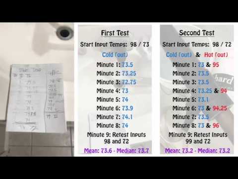
Red numbers for the second test are from us adding an additional step of testing the temperature of the exiting warm water. This was done because we were interested to see how much heat was lost in the complete process and how that compared to what was being measured as transferred to/gained by the incoming cold water. As discussed in details in the Heat Exchanger Engineering Details section, only a 3.5º F/2º C change is needed to make this a viable system. Those calculations showed this would be doable and we consider the above test results as further confirmation.
TEST LIMITATIONS
We consider the above test results quite good considering the limitations of our testing process. As mentioned in the video above, the largest limiting factor for this test was an inability to duplicate how cold ground water will be in our location versus the much warmer ground water in California where the test above was run. This difference in incoming water temperature could be as much as 25º F, which would dramatically improve heat transfer from the warm shower water going down the drain into the incoming cold water coming from the well.
The fact that this is a community-used shower that will run with back-to-back showers would also predictably increase efficiency with each shower. Even our testing with just two showers showed a doubling of efficiency from the first shower to the second one.
Colder ambient temperatures would lower efficiency. Warmer shower temperatures would further improve efficiency. Difficulty reading the thermometer accurately also made gathering precise data difficult.
One other limitation of our testing was our inability to effectively maximize internal pressure for the test unit. Maximizing that pressure would further improve efficiency because it would increase the surface area of cold-water contact with the copper pipe the hot water ran through. This would further increase heat transfer.
Our design is also limited in length by the space beneath the shower structure itself. More space would allow for a longer heat exchanger and that would also increase efficiency through increasing the surface area of cold-to-hot water exposure.
HEAT RECYCLING DESIGN DETAILS
WHAT IS A HEAT EXCHANGER
A heat exchanger is a semi-closed thermodynamic system that transfers energy in the form of heat from a hot gas or liquid to a cold gas or liquid. To maximize efficiency, the two fluids flow in opposite directions (counter flow).
The amount of energy required to heat water for taking a shower is almost completely lost because the water reaches the drain with almost the whole amount of energy used to heat it. This water is typically at a relatively high temperature (â°Ë†35ËšC / â°Ë†98ËšF).
It is possible to reuse this energy in the form of heat to pre-heat any desired fluid. This reduces the money that you would spend on energy and also helps to reduce the environmental impact caused by the mass “production” of energy and its side effects.
For our calculations, we used an average shower temperature of 40.5˚ C / 102˚ F and a minimum temperature of 12.78˚ C / 55˚ F for the incoming water. For any amount we pre-heat the water before it reaches the shower there will be a reduction in the amount of energy that the shower demands to heat the water to the desired temperature. The amount of energy required to heat the water can be calculated using the following equation.

Running this equation in a software called MATLAB® produces the following plots showing the relation between the temperature of the pre-heated water and the energy spent by the shower.

As shown above, if you can pre-heat the water to the desired temperature the shower would not need to use energy at all.
WHY USE A HEAT EXCHANGER
A heat exchanger can help to save energy that would otherwise be lost. Energy can’t be created or destroyed, energy can only be transformed from one form to another. Based on thermodynamics’ laws it is possible to understand that every time that we use an available form of energy to realize any work desired, some percentage of this energy is lost as heat, vibration, or other form of mechanical energy. A heat exchanger can reutilize this residual energy.
HEAT EXCHANGER ENGINEERING DETAILS
The project below was designed to be made with regular objects that can be found in your average hardware store.
The project consists of a tubular heat exchanger. This exchanger is made of copper tube (transporting warm water from the shower drain) inside a PVC tube (transporting cold water to the shower). Copper is recommended for the warm shower-drain water because it conducts heat very well. PVC is recommended for the cold water traveling to the shower head because it can isolate the heat well enough.
Heat exchange occurs between the hot water (after the shower) and cold water (which comes from the reservoir). The water from the reservoir is pre-heated and then passes through the electrical heater in the shower. For this exchanger to be sufficiently efficient to justify its use, we need at least two degrees Celsius (3.5º F) increase in the temperature of the water from the reservoir traveling to the shower head.
Key design factors to be considered were:
- The necessary pipe diameters for sufficient grey water flow
- The necessary pipe diameters for sufficient shower water flow
- Average temperature of the in-flow water ready to be used
- Desired average temperature of the water for use during a shower
- Standard pipe sizes available in most hardware stores
Duplicable hand calculations are shown below for various lengths of the heat exchanger. Software calculations (also shown below) were used to simulate the more complex temperature, pressure and heat transfer rates and behaviors.
For every calculation and simulation presented in this report we considered that the walls in the heat exchange system are adiabatic, which means the system will not lose heat to the environment. While this is in actuality not true, it simplifies the calculations to match known heat transfer’s rules and equations without compromising the accuracy of these equations for evaluating the design itself.
HEAT EXCHANGER PIPING-LENGTH CALCULATION REPORT:
For the theoretical calculation of the heat exchanger, we had to consider some extreme conditions to ensure that the system achieves the desired results. Below we display all the equations that we used to determine the piping length needed according to how much we wanted to increase the water temperature entering the shower.
The water properties specified above were calculated for the mean temperature in each condition of the water. For example, the first condition, hot water going from 35º C to 33º C. So the mean temperature in this case is (35+33)/2 which results in 34º C. With this value we can then reference water property tables to provide the data points needed for the necessary calculations:
INTERNAL FLUID FLOWING THROUGH THE INNER TUBE OF COPPER (WATER)
For the internal and external fluids, we considered the following conditions:
- Fluid temperature entering (from the drain) ” Th,i (Temperature Hot In): 35º C = 308.15 K = 95º F;
- Fluid temperature coming out (grey water) ” Th,o (Temperature Hot Out): 33º C = 306.15 K = 91.4º F;
- Mean temperature: 34ºC (93.2ºF);
- Water mass flow: 227.4 kg/h = 0.06316667 Kg/s = 1 GPM;
- Specific Heat (constant pressure – Cp): 4.1796 KJ/Kg.K;
- Thermal conductivity (K): 621.716 mW/m.K;
- Viscosity (µ): 734.92 µPa.s;
- Density (ρ): 994.314 Kg/m³.
EXTERNAL FLUID (WATER)
- Fluid temperature entering (from the reservoir) ” Tc,i (Temperature Cold In)::12.78 ºC = 285.93 K = 55 ºF;
- Fluid temperature coming out (entering on the shower) ” Tc,o (Temperature Cold In):: 14.77 ºC = 287.92 K = 58.58 ºF;
- Mean temperature: 13.775 ºC (56.79ºF)
- Water mass flow: 227.4 kg/h = 0.06316667 Kg/s = 1 GPM;
- Specific Heat (Cp): 4.1911 KJ/Kg.K;
- Thermal Conductivity (K): 586.1205 mW/m.K;
- Viscosity (µ): 1195.529 µPa.s;
- Density (ρ): 999.2629 Kg/m³.
TUBE DIMENSIONS:
Inner Tube (2” – copper):
The grey water needs at least a 2″ pipe to drain efficiently.
- Internal copper pipe diameter: 52.5 mm
- External copper pipe diameter: 60.33 mm
Outer Tube (3″ – PVC):
The section area between the two pipes (3″-2″) should be 1″ to maintain pressure and flow rate:
- Internal PVC pipe diameter: 77.93 mm
- External PVC pipe diameter: 88.90 mm
GREY WATER HEAT FLOW:
The first thing to calculate is the heat flow (Q) that the internal fluid (hot water) is capable of transferring within the system, considering that this water will lose 2 ºC (from 35º C to 33º C). The equation to calculate this is:
We’ll call this Equation 1 (EQ1): Q = m x Cp x ∆t
Where,
- Q = Heat flow [J/s];
- m = Mass flow [Kg/s];
- Cp = Specific Heat at constant pressure [J/Kg.K];
- ∠t = Temperature variation [ºC] or [K].
So,
- Q = 0.06316667 [Kg/s] x 4179.6 [J/Kg.K] x (35 ” 33) [K] = 528 [J/s]
Now we can use the same equation (EQ1) while assuming the heat going from the hot water is going exclusively to the cold water, because the hot water is traveling exclusively inside the cold water for the heat exchange. Equalizing these equations it’s possible to find out the final temperature of the pre-heated water (which is the exchange of heat from the hot water with the heat received by the cold) as the external fluid temperature entering in the shower:
- Qh = mh x Cph x ∠th = mc x Cpc x ∠tc
Where ‘h’ means all the data for the hot water (inside the internal tube) and ‘c’ means all the data for the cold water.
So,
- 528.02 [J/s] = 0.06316667 [Kg/s] x 4191.1 [J/Kg.K] x (T2 ” 12.78) [K]
After this, we will calculate the ∠t1 and ∠t2, which are used to calculate the Logarithmic mean temperature difference (LMDT), which will be used in another equation by the end of this project:
Equation 2 (EQ2): ∆t1 = Th,i – Tc,o
Equation 3 (EQ3): ∆t2 = Th,o – Tc,i
Equation 4 (EQ4): LMTD = (∆t2 – ∆t1) ÷ [ln (∆t2 ÷ ∆t1)]
So,
- ∠t1 = 35 ºC – 14.77 ºC = 20.23 ºC
- ∠t2 = 33 ºC -12.78 = 20.22 ºC
- LMDT = (20.22 ” 20.23) ÷ [ln (20.22 / 23.23] Â
Next we need to calculate the internal heat transfer coefficient (hi), which means how much heat the inner flow (water inside the copper tube) is able to transfer to the system. For this, we need to calculate some dimensionless parameters, like Reynolds number inside the copper tube and Nusselt number inside the copper tube:
First, for Reynolds number we will use the following equation:
Equation 5 (EQ5): Re,i = (4 x mi) ÷ Ï€ x Di x µ  Ò Ã’ Ã’ Ã’ Ã’ Ã’ Ã’ Ã’ Ã’ Ã’ Ã’ Ã’ Ã’ Ã’ Ã’ Ã’ Ã’ Ã’ Ã’ Ã’ Ã’ Ã’ Ã’ Ã’ Ã’ Ã’ Ã’ Ã’ Ã’ Ã’ Ã’ Ã’ Ã’ Ã’ Ã’ Ã’ Ã’ Ã’ Ã’ Ã’ Ã’ Ã’ Ã’ Ã’ Ã’ Ã’ Ã’ Ã’ Ã’ Ã’ Ã’ Ã’ Ã’ Ã’ Ã’ Ã’ Ã’ Ã’ Ã’ Ã’ Ã’ Ã’ Ã’ Ã’ Ã’ Ã’ Ã’ Ã’ Ã’ Ã’ Ã’ Ã’ Ã’ Ã’ Ã’ Ã’ Ã’ Ã’ Ã’ Ã’ Ã’
Where,
- Re,i = Reynolds number inside the internal tube
- mi = Water flow inside the internal tube [Kg/s]
- Di = Copper tube internal diameter [m]
- µ = Viscosity [Pa.s]
- π = 3.1416
So,
- Re,i = (4 x 0.06316667[kg/s]) ÷ (3.1416 x 0.0525[m] x 0.00073492[Pa.s])
Now, the Nusselt number inside the tube using the following equation:
Equation 6 (EQ6): Nu,i = 0.023 x Re,i ^ (0.8) x Pr ^ (0.4) Â Ã’ Ã’ Ã’ Ã’ Ã’ Ã’ Ã’ Ã’ Ã’ Ã’ Ã’ Ã’ Ã’ Ã’ Ã’ Ã’ Ã’ Ã’ Ã’ Ã’ Ã’ Ã’ Ã’ Ã’ Ã’ Ã’ Ã’ Ã’ Ã’ Ã’ Ã’ Ã’ Ã’ Ã’ Ã’ Ã’ Ã’ Ã’ Ã’ Ã’ Ã’ Ã’ Ã’ Ã’ Ã’ Ã’ Ã’ Ã’ Ã’ Ã’ Ã’ Ã’ Ã’ Ã’ Ã’ Ã’ Ã’ Ã’ Ã’ Ã’ Ã’ Ã’ Ã’
Where,
- Nu,i = Nusselt number inside the internal tube (copper)
- Pr = Prdtl number for the mean temperature (Pr = 4.994)
- Re,i = Reynolds number inside the internal tube
So,
- Nu,i = 0.023 x 2084.48 ^ (0.8) x 4.994 ^ (0.4)
With these numbers we are able to calculate the internal heat transfer coefficient (hi) by the equation:
Equation 7 (EQ7): hi = (Nu,i x K) ÷ Di  Ò Ã’ Ã’ Ã’ Ã’ Ã’ Ã’ Ã’ Ã’ Ã’ Ã’ Ã’ Ã’ Ã’ Ã’ Ã’ Ã’ Ã’ Ã’ Ã’ Ã’ Ã’ Ã’ Ã’ Ã’ Ã’ Ã’ Ã’ Ã’ Ã’ Ã’ Ã’ Ã’ Ã’ Ã’ Ã’ Ã’ Ã’ Ã’ Ã’ Ã’ Ã’ Ã’ Ã’ Ã’ Ã’ Ã’ Ã’ Ã’ Ã’ Ã’ Ã’ Ã’ Ã’ Ã’ Ã’ Ã’ Ã’ Ã’ Ã’ Ã’ Ã’ Ã’ Ã’ Ã’ Ã’ Ã’ Ã’ Ã’ Ã’ Ã’ Ã’ Ã’ Ã’ Ã’ Ã’ Ã’ Ã’ Ã’ Ã’ Ã’ Ã’ Ã’ Ã’ Ã’ Ã’ Ã’ Ã’ Ã’ Ã’ Ã’ Ã’ Ã’
Where,
- hi = Internal heat transfer coefficient [W/m².K]
- Nu,i = Nusselt number inside the internal tube (copper)
- K = Thermal conductivity for the mean temperature [W/m.K]
- Di = Copper tube internal diameter [m]
So,
- hi = (19.78 x 0.621716[W/m.K]) ÷ (0.0525 [m])
After calculating the internal heat transfer coefficient we have to calculate the external heat transfer coefficient (he). For that we need to recalculate the dimensionless numbers (Reynolds number and Nusselt number) again, but now for the external water (between the PVC pipe and the copper tube).
First we calculate the external Reynolds’ number:
Equation 8 (EQ8): Re,e = (4 x mo) ÷ [Ï€ x (De + Di) x µ] Â Ã’ Ã’ Ã’ Ã’ Ã’ Ã’ Ã’ Ã’ Ã’ Ã’ Ã’ Ã’ Ã’ Ã’ Ã’ Ã’ Ã’ Ã’ Ã’ Ã’ Ã’ Ã’ Ã’ Ã’ Ã’ Ã’ Ã’ Ã’ Ã’ Ã’ Ã’ Ã’ Ã’ Ã’ Ã’ Ã’ Ã’ Ã’ Ã’ Ã’ Ã’ Ã’ Ã’ Ã’ Ã’ Ã’ Ã’ Ã’ Ã’ Ã’ Ã’ Ã’ Ã’ Ã’ Ã’ Ã’ Ã’ Ã’ Ã’ Ã’ Ã’ Ã’ Ã’ Ã’
Where,
- Re,e = Reynolds number inside the external pipe (between PVC and copper)
- mo = External water mass flow (between PVC and copper) [Kg/s]
- π = 3.1416
- De = PVC pipe internal diameter [m]
- Di = Copper tube internal diameter [m]
- µ = Viscosity [Pa.s]
So,
- Re,e=(4×0.06316667[Kg/s])÷[πx(0.07793+0.0525)[m]x1195.529×10^-6[Pa.s]]
Now, to calculate the external Nusselt number we have to use the table 8.2 from the textbook Fundamentals of Heat and Mass Transfer: 6th Edition. :

Our Di/De is given by (52.5/77.93) which is equal to 0.6736.
As we do not have this specific value in the table, we have to make an interpolation by the following way:

Now it is possible to calculate the external heat transfer coefficient (he) using the parameters that we calculated:
- he = (K x Nu,e) ÷ (De ” Di) Â Ã’ Ã’ Ã’ Ã’ Ã’ Ã’ Ã’ Ã’ Ã’ Ã’ Ã’ Ã’ Ã’ Ã’ Ã’ Ã’ Ã’ Ã’ Ã’ Ã’ Ã’ Ã’ Ã’ Ã’ Ã’ Ã’ Ã’ Ã’ Ã’ Ã’ Ã’ Ã’ Ã’ Ã’ Ã’ Ã’ Ã’ Ã’ Ã’ Ã’ Ã’ Ã’ Ã’ Ã’ Ã’ Ã’ Ã’ Ã’ Ã’ Ã’ Ã’ Ã’ Ã’ Ã’ Ã’ Ã’ Ã’ Ã’ Ã’ Ã’ Ã’ Ã’ Ã’ Ã’ Ã’ Ã’ Ã’ Ã’ Ã’ Ã’ Ã’ Ã’ Ã’ Ã’ Ã’
Where,
- he = External heat transfer coefficient [W/m²K];
- K = Thermal conductivity for the mean temperature [W/m.K];
- Nu,e = External Nusselt number between PVC and copper;
- De = PVC pipe internal diameter [m];
- Di = Copper tube internal diameter [m].
So,
- he = (586.1205 x 10^-3[W/m.K] x 4.575) ÷ (0.07793 ” 0;0525) Â
After that we are able to discover the global heat transfer coefficient (U) that considers both he and hi in your calculation:
U = 1 ÷ ([1/he] + [1/hi]) Â Ã’ Ã’ Ã’ Ã’ Ã’ Ã’ Ã’ Ã’ Ã’ Ã’ Ã’ Ã’ Ã’ Ã’ Ã’ Ã’ Ã’ Ã’ Ã’ Ã’ Ã’ Ã’ Ã’ Ã’ Ã’ Ã’ Ã’ Ã’ Ã’ Ã’ Ã’ Ã’ Ã’ Ã’ Ã’ Ã’ Ã’ Ã’ Ã’ Ã’ Ã’ Ã’ Ã’ Ã’ Ã’ Ã’ Ã’ Ã’ Ã’ Ã’ Ã’ Ã’ Ã’ Ã’ Ã’ Ã’ Ã’ Ã’ Ã’ Ã’ Ã’ Ã’ Ã’ Ã’ Ã’ Ã’ Ã’ Ã’ Ã’ Ã’ Ã’ Ã’ Ã’ Ã’ Ã’ Ã’ Ã’ Ã’ Ã’ Ã’
Where,
- U = Global heat transfer coefficient [W/m².K];
- he = External heat transfer coefficient [W/m².K];
- hi = Internal heat transfer coefficient [W/m².K].
So,
- U = 1 ÷ ([1/105.44] + [234.23])
Finally, with all these results, we can include the linear length needed to heat the cold water from 12.78ºC (55ºF) to 14.77ºC (58.58ºF) by the following equation:
- L = Q ÷ (U x Ï€ x Di x LMTD) Â
Where,
- L = Linear length needed;
- Q = Heat flow [J/s];
- U = Global heat transfer coefficient [W/m².K];
- π= 3.1416;
- Di = Copper tube internal diameter [m];
- LMTD = Logarithmic mean temperature difference [K] or [ºC].
So,
- L = 528.02[W] ÷ (72.709[W/m².K] x π x 0.0525[m] x 20.22[K])
Therefore, with this example we can see that even with cold water (12.78ºC/55ºF) it is possible to heat the water by two degree Celsius using 2.17 meters of linear piping with the pipes diameters as specified. So, anyone can build a tabulation like that and fit it on their home hydraulic system reducing the energy consumed by the shower or boiler. It is possible that an infinite amount of parameters exist and need to be considered in a heat exchanger design like that, so depending on the diameters, temperatures and mass flow, we can get a lot of different results.
For the calculations, using computer programs, on heat transferred and the necessary tubes length, we are using a Brazilian simple software that is free and can provide all the information that we need. To run the calculations we used the following data and considerations (for winter):
- External copper pipe diameter: 60.33 mm
- Internal copper pipe diameter: 52.50 mm (2″)
- External PVC pipe diameter: 88.90 mm
- Internal PVC pipe diameter: 77.93 mm (3″)
- Hot water temperature entering (going down the drain): 35 ºC (95 ºF)
- Hot water temperature coming out from the system: 33 ºC (91.4 ºF)
- Cold water temperature entering (from the reservoir): 12.78 ºC (55ºF)
- Cold water temperature coming out from the system (entering in the shower): 13.78 ºC (56.8 ºF)
- Shower water flow: 227.4 Kg/h (1 GPM)
- Linear length needed (after calculation): 7.14 m
Below are images from the software and the results generated by it:


With the help of the software, we can see that in order to increase the heat of the cold water by one degree Celsius, we need a 7 meter linear length. This software is much more accurate and takes into consideration many more factors to design. So, basically this software considers more problems that can disrupt the heat exchange which explains why it is necessary to have more length to change just one degree. Another thing to remember is that these calculations are based on using very cold water temperatures coming from the reservoir which occurs in particular places. In a place where the water is warmer less linear length will be needed to build a heat exchanger to transfer the same amount of heat.
After evaluating the calculations handmade and also software calculations based on the software, we used the CAD software Solidworks® to develop a design for the heat exchanger and evaluate it using hydraulics and thermal simulations.
HEAT EXCHANGER DESIGN 1
In the first design, we considered a large heat exchange between the reservoir water going to the shower and gray water from the shower. We designed a heat exchanger 300 linear inches long made of PVC pipes with copper pipes inside. The following pictures show the design, the pressure drop inside the system and the amount of heat able to transfer to the water going to the shower:

Figure 1: First design.

Figure 2: The streamlines generated inside of the heat exchanger system where the colors define the temperature value.

Figure 3: Temperature distribution inside the system.

Figure 4: Pressure distribution inside the system.
However, to we had to match all the requirements from the hydraulic team. The grey water coming from the shower drain requires a higher pressure to flow, this way the use of gravity pushing the grey water down helps to eliminate the need to pressurize this water. Our initial solution for solving this problem was to incline the whole system matching the hydraulic system’s slope, however due to the fact that the pipes were parallel to each other we would have both positive and negative gravitational force gradients at work. Therefore the gravity would both help and deter the grey water to flow.
The second idea for a solution for this problem was to incline independently each pipe in this system, however several changes were required such as changing the 180 degrees copper elbow to a 90 degrees copper elbow.
The difference in angle and height made it impossible to connect the pipes in a reliable way. After analyzing and trying several possible solutions the only one that seems viable was to make the design simpler with just one pipe reducing the length to ⦜ of the original.

Figure 5: The connection problem due to the difference in height and angle in the pipes.
HEAT EXCHANGER DESIGN 2
The second design created can be made using simple hardware found in regular hardware stores such as Home Depot. The items required to build the system are:
- One copper pipe Sch 40 with 2 inches in diameter and 120 inches in length, average price of 43.00 USD for exactly 10 feet.
- One PVC pipe Sch 40 with 3 inches in diameter and 100 inches in length, average price of 245.00 USD for a linear length of 10 feet however since the price for a linear length of 20 feet is still the same I would recommend buying a larger length and cutting it saving the extra pipe for a second design.
- Two PVC reducing tee connections Sch 40 with the diameters of 3x3x1.5 inches, average price of 13.28 USD.
- Two rubber fillings with 3 inches in diameter, average price of 4.44 USD each.
The total price to build one system would be 200.94 USD. However the price can change based on the modifications the user can make in the original design and the suppliers for the parts.
Below is a representation of the design:

Figure 6: Second design.
After designing the system, we ran simulations to see where we would have drops in the pressure and how the system would react with the slope required from the hydraulic team.
For this simulation we used the pressure over the hot water coming from the drain as the environmental pressure 101325 Pa and the pressure over the cold water coming from the reservoir as 80 Psi and the temperatures are the same as the calculations already presented.
The results are presented below:

Figure 7: Pressure value inside of the system.

Figure 8: Temperature inside of the system.

Figure 9: Flow streamlines simulation inside of the system.
HEAT EXCHANGER DESIGN 3
The third (and final) design created can be made using simple hardware found in regular hardware stores such as Home Depot. The items required to build the system are:
- One copper pipe Sch 40 with 2 inches in diameter and 3.6 feet in length, average price of 43.00 USD for exactly 10 feet.
- One PVC pipe Sch 40 with 3 inches in diameter and 26.48 inches in length, average price of 245.00 USD for a linear length of 10 feet however since the price for a linear length of 20 feet is still the same I would recommend buying a larger length and cutting it saving the extra pipe for a second design.
- Two PVC reducing tee connections Sch 40 with the diameters of 3x3x1.5 inches, average price of 13.28 USD.
- Two rubber fillings with 3 inches in diameter, average price of 4.44 USD each.
The total price to build one system would be 200.94 USD. However, the price can change based on the modifications the user can make in the original design and the suppliers for the parts.
Below are the images of the design and the simulations:

Figure 10: Final design.

Figure 11: Pressure value inside of the system.

Figure 12: Temperature inside of the system.

Figure 13: Flow streamlines simulation inside of the system.
The water coming from the hot water outlet has a temperature equal to 304.27 K or 31.12 ⁰ C (88ºF) and the water coming from the cold water outlet has a temperature equal to 289.7K or 16.55 ⁰ C (61.79ºF). With these results it is possible to reduce the showers power supply by 1.17 Kilowatts knowing that a regular shower has a power supply of 8.5 Kilowatts, the energy reduction would be around 13.76%. The time required for having an economical compensation for the price paid on the heat exchanger depends on the average price for a Kwh in the location that the heat exchanger will be used. Since the average price for a Kwh is normally low, it takes a little bit of time to receive the savings. However, the reduction of environmental impacts definitely justify the system.
Heat exchangers have been used in the industry for several years, now it is time to apply the industry’s technology that we normally associate with degrading our environment to help save it. It is time to use energy in a smarter way. Let’s exCHANGE our energy use!
WATER SAVING METHODS

Water saving methods will include the measures below. They are listed in order of importance with our primary criteria being water conservation and then energy savings. The approaches listed first are considered of most importance because they are “passive” approaches. This means they will save water and energy just by including them as functional components of the design. User Education is listed near the bottom because, to be effective, it requires the decision to participate and change behaviors.
- Water-saving Shower Heads
- Environmental Comfort Controls
- Thermostatic Mixing Valves & Point-of-use Water Heaters
- User Education
- Other Measures
SHOWER HEADS
 Water conservation is a foundation of One Community’s open source strategy for building a global collaboration of self-sufficient and self-sustainable teacher/demonstration communities, villages, and cities for The Highest Good of All. One of the biggest ways to conserve water is through modifications to daily habits that use a lot of water. Showers are a common area of focus and also an important part of most people’s day so we invested over 40 hours assessing the diversity of water-saving shower heads available so we could include them as part of our open source contribution to comprehensive sustainable living.
As part of these communal shower structures, we’ll be testing a variety of the best water-saving shower heads on the market. We’ll then share the user feedback and longterm user usage patterns/data as an open source sharing of how the different shower heads compare to each other. These usage patterns/preferences will then be used to guide our purchasing decisions for the other 6 villages.
You can read more about this topic on the Water-saving Shower Heads page.
ENVIRONMENTAL COMFORT CONTROLS
Environmental comfort controls are designed into the shower structures to additionally save water. They include use of heaters and timers.
HEAT LAMPS
 It is our hope that the addition of heat lamps in the bathing and dressing area will help reduce water and energy consumption as well. The assumption is that the addition of a heat lamp to the showering area either causes the showerer to decrease the time in the water or decrease the temperature to which the shower is set. Heat lamp effectiveness, however, is hard to analyze because it depends on a person’s comfort level at different distances.
Here are the calculations we can do though: If we were to use two 250W Heat lamps like the ones shown at left, the benefit would need to either make the user shorten their shower time by more than 47 seconds on average, or decrease their temperature by 1.3°C (2.34°F) or more to be a net savings of energy and/or water.
TIMERS
Using timer-switches to reduce negligent energy use is not a new idea. It is common to see these switches on large energy consuming devices that serve guests (i.e. hot tubs, saunas, and heat lamps.) The idea is simple, the person selects how much time they will use the unit (i.e. 5 minutes) and the unit will only operate while that countdown is going. If the person wants more time, they select more time. Nothing prevents the person from using the device, but it requires that the person be present to reset the timer. This saves the facility from having to power the device while no one is using it.
There are many options on the market for timers for standard devices, but what time selection would be the best for energy saving? We shall put timers on the Heat Lamps, which is a semi-standard practice, and separate timers on the showers.
The heat lamp, along with allowing a person to take cooler showers, would also serve as a time-metering device while in the water. Since while in the shower most of us are without our time devices, the heat lamp and shower timers would also act as timekeepers, turning off after an allotted time.
But what length of time would yield the best results? It figures that a long timer would not alert the showerer and the shower would run long. However, a very short timer would cause the person to adjust it over and over perhaps interrupting the showering and creating a longer shower time as well.
Since this is a question of human behavior we will have to see what effect different timers have on the energy and water use in the shower areas. With several showering facilities, we can (and will) test the different timers against each other in an experiment. Here is the initial plan:
1/4 of the showers will have:
- Longer timer for water (10 minutes) and connected to the heating lamp in shower, 3-min heat lamp timer in the changing area
1/4 of the showers will have:
- Shorter timer for water (6 minutes) and connected to the heating lamp in shower, 3-min heat lamp timer in the changing area
1/4 of the showers will have:
- Longer timer for water (10 minutes), separate 5-minute heating lamp timer in shower, 3-min heat lamp timer in the changing area
1/4 of the showers will have:
- Shorter timer for water (6 minutes), separate 3-minute heating lamp timer in shower, 3-min heat lamp timer in the changing area
More analysis is needed to design the experiment thoroughly, however, the idea remains the same:
Clearly identify how to use maximum comfort of the shower and changing environment, combined with convenient ways to self-monitor and adjust water temperature and time showering, to maximize water and energy savings.
VIDEO COMING OF: USING HEAT LAMP AND SHOWER TIMERS TO SAVE WATER AND ELECTRICITY – THIS TUTORIAL WILL SHARE THE RESULTS AND CONCLUSIONS FROM ALL OF THE ABOVE TESTS
SEE OUR HOW TO HELP AND/OR CROWDFUNDING CAMPAIGN PAGE TO HELP CREATE ALL THE TUTORIAL VIDEOS FASTER
THERMOSTATIC MIXING VALVES & POINT-OF-USE WATER HEATERS
A thermostatic mixing valve (TMV) is a valve that blends hot water with cold water to ensure constant and safe shower and bath outlet temperatures. The use of a thermostat, rather than a static mixing valve, provides:
- Increased safety against scalding
- Increased user comfort, because the hot-water temperature remains constant
- Possible energy savings (as shown by the calculations below)
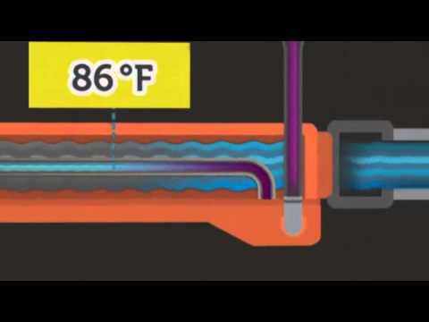
This graphic shows the inner workings of these valves and how the thermostatic element (regulated in many by a wax thermostat) moves to change the amount of hot and cold water that mixes. In the case of a water pressure loss and/or hot or cold supply failure, water is shut off rapidly (less than 2 seconds) to prevent scalding or thermal shock.

Inside a Thermostatic Mixing Valve and How the Thermostatic Element Moves to Control Water Temperature

In short, if output temperature is important, a thermostatic mixing valve can give you the exact temperature you desire. This gives you control over your water temperature much like a thermostat gives you control of room temperature in your house. You set a desired temperature and the device opens or closes the hot water valve in order to maintain the proper temperature setting. In the case of our showers, the valve would only use the point-source water heater when necessary to attain the correct temperature thus decreasing the probability of wasted hot water and the resultant wasted energy. The ease of use and safety of these valves make them perfect for domestic use. Because the temperature can be set before the water is turned on, the user can depend on, and monitor the temperature of the water that they are using. This is helpful to prevent scalding injury and to limit only the necessary hot water usage to the user of the shower.
The constant temperature output make them well-suited for in floor thermal heating such as the system utilized in the Duplicable City Center. An input from a BACNet (building automation and control networks) to a digital thermostatic valve (or regulator) would ensure that the temperature of the water running through the radiant heating system would be the correct (and safe) temperature to heat the space safely.
Though the units themselves are hardly more-or less expensive than a “normal” shower valve, the main benefit to One Community and others is the ability to control the exact temperature of the shower.
Let’s do a thought experiment to see what a reduction of 1°C in everybody’s shower would mean in terms of energy, water, and money. For this experiment we’ll assume that the average shower flow rate is 1.5 GPM and the average shower is 8 minutes. Energy is usually measured as the amount of energy it takes to raise a amount of water by a certain temperature. So finding energy from a water temperature increase, or decrease, is relatively simple.
Raising 1.5 gallons of water per minute by 1°C would be the same as 52.20 watt-hours (WH) worth of energy for every shower. When you consider that 150 people will be taking showers every day, that adds up to nearly 7.83 kWh every day.
HERE’S SAVINGS ANALYSIS FOR JUST 1 DEGREE OF DIFFERENCE

At the standard rate of 10¢ per kWh this is only 78¢ per day difference. However, One Community, being off-grid, pays dearly for it’s power and the infrastructure needed to provide that extra 7.83 kWh/day would cost nearly $11,700 of extra infrastructure. That power-generating infrastructure would need to be purchased before the buildings were built.
What does that 7.83 kWh/day of energy really amount to? It’s 6,740 Calories for you gym people. It’s 5.5 standard 60W incandescent bulbs left on all day. It’s the amount of energy in a quarter gallon of gasoline (about 6 miles driving in the average car). Or, It’s 23 miles driving an electric car.

1 Degree = 6,740 Calories – Over 12 of these bad boys.
All that, every day, in just one degree difference for 150 people.
WATER AT THE TEMPERATURE YOU WANT, WHEN YOU WANT IT
The biggest water savings, however, would come from the immediacy of the correct temperature upon starting the shower. Three factors affect the timing of the hot water’s arrival to an individual about to take a shower:
- Distance from the Heater to the outlet
- The reaction time of the thermostatic mixing valve
- The distance from thethermostatic mixing valve to the showerhead
In a ½” pipe there are 0.002236 gallons per inch of pipe. At a standard shower flow rate of 1.5 GPM we can find that it takes 0.04403 seconds per inch for water to move through it. When the TMV is opened the valve will be sensing cold and therefore the hot water will be completely open. The water heater would heat the water and it would start to rise up to the thermostatic mixing valve. The valve would not begin to react to the hot water until the water reached that point.
If the heater is 36″ from the valve it would take 1.59 seconds before the valve would react. The NHS D08 TMV Model Engineering Specification makes reference to this, and permits a 7°C temperature ‘spike’ to last for 1.2 seconds, with 50°C permitted for a maximum of 0.5 seconds. Assuming incoming hot water as a “spike” the valve would react to the correct temperature in about 1.7 seconds. Assuming 36″ again for the mixed water pipe from the valve to the showerhead, the correct temperature would come out of the shower head 1.59 seconds after the TMV has found the correct temperature.
Total estimated time from start of shower to correct temperature:
1.59s + 1.7s + 1.59s = 4.88s
Now this may not seem like much time savings, I’m sure in the showers in your own home you have a pretty good idea of where the shower valve needs to be to give you the best temperature. Where this valve shines is its ability to work consistently no matter which shower you use.
When entering a strange shower people usually take time to adjust the temperature and find the right position for their comfort. In a large group of people using several different showers, the ability to get an ideal temperature in a shower in less than 5 seconds, no matter what shower, adds up to consistent and significant savings in water and power.
Let’s assume a 5-second savings:
- Water: 1.5 gallons/minute * 5 seconds * 1 minute / 60 seconds = 1/8th gallon per person for 150 people: 150 *.125 = 18.75 gallons per day.
- Energy: average shower temperature = 105°F (40.5°C) The amount of energy it takes to raise one gallon of water from 55°F (13°C) to 105°F (40.5°C) is 415 BTUs (121.62 Wh)
18.75 gallons/day * 121.62 Wh/gallon = 2280.46 Wh/day (2.28 kWh/day) of savings (in addition to any savings created by people choosing to shower at 1 degree cooler – as described above).
USER EDUCATION
User education is another huge aspect of how One Community intends to help with water and energy conservation. Educating people about how their patterns affect power and water consumption will be addressed through infographics in the changing areas and plaques on the wall sharing details like:
- National averages and the affects of reducing a shower by just 1 minute
- National averages and the affects of reducing a shower by just 1º
- How much water a person saves just by using the low-flow shower heads
- How much water a person saves just by using the thermostatic mixing valves
- How much energy and water a person saves by using the heat lamps in the showers
- How much energy and water a person saves by turning off a shower to soap up
In addition to this, making adjustments to personal-use patterns will be easy to do and measure through clear labels on the timers and thermostatic mixing valves that show national time and temperature averages along with the savings and costs of using more or less than these averages. Improving a person’s usage is then as simple as setting their time or temperature lower than the averages and/or their own usual use.
 All visitors and residents of One Community will also have the option and ability to specifically monitor and compare their usage patterns to the averages of others. Data gathering and comparisons will be made possible using the open source control, automation, and data gathering systems we’re developing along with unique QR codes (like the one here), card readers for their room keys, and private pin numbers for accessing the related and anonymous data. Through a system like this, all a person interested in detailed data on their usage will need to do is swipe their card or scan the QR code at the area they are about to use or enter. This will then associate their resource usage data with their private pin number and give them the ability to run a personal report at the end of their stay and compare their usage with that of other countries, national averages, visitor averages at One Community, and resident averages at One Community.
Complete details on the control, automation, and data gathering systems designs, security, privacy, etc. can be found on the related page. Our hope, after using a system like this, is that people will better understand their patterns and how their individual choices affect usage. With that understanding some visitors may also choose to change their patterns once they return home.
CLICK HERE TO READ OUR PRIVACY POLICY
OTHER MEASURES
Shower preferences could also lead to shorter showers if a clear preference becomes apparent. Because of the diversity of options that will be used and evaluated as described in the Water-saving Shower Heads, some shower heads may become more in demand than others. This could lead to those using a shower faster if there is a friend waiting for that specific shower and/or subtle encouraging of others to take a faster shower because someone else is waiting to use it too. Of course, if this demand becomes great enough, least popular shower heads will be replaced with the most popular ones.
Other measures are being considered in addition to the different approaches described above. One idea is possible incorporation of a small light that would come on when a specific resource usage runs especially long. Another might be to offer residents and/or visitors optional competitions and incentives for demonstrating exceptional conservation. Additional ideas will be added here as they are explored. Click here if you have a suggestion to add.
GREYWATER USE & WATER PRE-HEATING IN THE TROPICAL ATRIUM
Greywater will be filtered below the shower structures and then used for watering in the Tropical Atrium. The Tropical Atrium will also be the initial place for pre-heating water used in the showers. This pre-heating will happen via the central stone floor that is directly above the water storage within the Atrium. Complete details for these designs are coming and will be shared in this section once complete.
ECOLOGICALLY FRIENDLY SOAPS
We researched ecologically friendly soaps also because we’ll be using the greywater from these showers for watering plants. Through this process we determined that ‘biocompatible’ soaps were really what we were seeking rather than ‘biodegradable’, ‘natural’, and/or ‘eco-friendly’ soaps as those latter three terms don’t mean much when it comes to how suitable they are for plants and soil.
More specifically, plants need to avoid:
- Sodium – very bad for plants, potassium-based soaps are better
- Boron (such as borax) – plants need a very small amount, above that amount it is very toxic
- Chlorine – toxic to plants (and people), use peroxide instead
- Phosphates – causes eutrophication (algae and plant overgrowth leading to hypoxia)
Liquid soaps tend to have less salts than bar soaps, because liquid-based soaps can use potassium-based lye, whereas bar soaps typically use sodium-based lye (some use glycerine, which is better than those made with lye). The amount of chemical additives in shower greywater though is usually negligible due to dilution. In general, even typical shampoos and conditioners don’t harm plants because they are low in salt and free of boron, and then highly diluted by the water used for the shower.
Our sustainability and health goals still warrant conscientious soap selection though. With this and the above details in mind, the following soaps have been determined as viable soap/shampoo/conditioner options that are biocompatible:
- Pure Castile Soap (like Dr. Bronner’s)
- Aubrey organics shampoo
- Some Burt’s Bees products
- Everyday Shea
- Trader Joe’s citrus shampoo and conditioner
- Mrs. Meyers bar soap
- Avalon shampoo and conditioner
When we make our final decision and are ready to purchase, our goal will be to coordinate large-scale (hopefully 50-gallon drum) purchase of the product we choose so we can eliminate packaging-waste, buy at the most affordable price, and provide our chosen soaps as the preferred option for all residents and visitors. If we can establish this kind of purchasing plan, our hope is that others will be able to purchase similarly.
RESOURCES
Below are the best online resources we have found relating to the Eco Shower Designs and water sustainability.
- Pacific Institute – Sustainable Water Management
- Product: EcoDrain – Easy to install home heat exchanger
- Product: Power-Pipe – Another easy to install home heat exchanger | Spec Sheet
- ‘Nebia’ atomizing showerhead saves 70% on water and gives a significantly superior shower
- Use this page (click here) if you have a resource you’d like to suggest be added here
Eco Drain Video


SUMMARY
The One Community Eco-Shower and Heat Exchange Team combined have spent hundreds of hours to gather the data, make the calculations, and generate the reports and images that are on this page. With this information in hand, we feel that we can truly say that we have put thought and energy into every area of the Eco-Shower Design process in order to produce the most sustainable system possible. We feel that with these designs and processes, One Community will save water, save energy, and create a more enjoyable shower experience for everyone. Combined with the additional water saving methods outlined above, One Community can collectively reach it’s goal of being as sustainable as it possibly can. Creating this internal water sustainability makes implementing our other designs and ideas much easier and more manageable, and allows us to reach our goals effectively. We hope you can use some or all of the information on this page for your own project or ideas, too.
FREQUENTLY ANSWERED QUESTIONS
Q: Is it worth it to build my own heat exchanger for home use?
It can absolutely be worth it. The temperature change may be slight, but over the course of a year, that can be hundreds of dollars, depending on the cost of your electricity. The colder the temperature of your ground-water, the more a heat exchanger may be a great option for your home too. If you aren’t a DIY type of person, EcoDrain also makes a heat exchanger for your home that is easy to use and install: Eco Drain – Easy to install home heat exchanger
Q: How is One Community going about reducing water and energy usage from showers?
One Community has designed the Eco Showers with sustainability in mind. We all enjoy having a warm or hot shower. The showering areas will be heated up so that the water will not need to be so hot. It is far more energy efficient to heat the air than it is to heat the water. We believe that this will ultimately create a more enjoyable showering experience while also using less water and energy overall. The heat exchanger will also pre-heat the incoming cold water with the warm greywater coming from the shower drain. We also plan on using water-saving shower heads to further reduce water usage.
Q: Why does the Earthbag village have 4 shower buildings providing a total of 20 showers?
The Earthbag Village will house an average of 150 people with a maximum capacity of 200. Twenty showers have been identified as ideal for this number of people.
Q: Can the heating system influence the thermostatic mixing valve’s performance?
Yes, if the TMV is installed incorrectly it will not operate optimally. The solution to this is to carefully follow the manufacturer’s installation suggestion.
Q: How quickly will a thermostatic mixing valve adapt when a user changes the shower water temperature?
Assuming 36″ for the mixed water pipe from the valve to the shower head, a TMVs temperature will changes in about 1.7 seconds, significantly faster than adjusting a traditional shower. This almost instant closure in the event of a hot or cold supply failure is what makes them so effective at preventing scalding or thermal shock.
Q: In regards to showering, what is the total water & energy usage per day expected for 150 people?
The following calculations do take into account the water saved from the water-saving shower heads but do not take into account the energy saved with heat exchangers and pre-heating water in the Tropical Atrium. Our actual energy usage will be far less.
Water: 1.5 GPM x 8 minutes = 12 gallons x 150 people = 1800 gallons per day
Energy: Average shower temperature = 105°F (40.5°C) The amount of energy it takes to raise one gallon of water from 55°F (13°C) to 105°F (40.5°C) is 415 BTUs (121.62 Wh)
121.62 Wh/gallon x 1800 gallons = ~219 KwH
Q: Is there any way to utilize the remaining hot water after it exits the heat exchanger?
As of now, it appears the remaining water heat will be too low to use. Options explored for use were heating the Tropical Atrium and heating the shower structure itself from below. The Tropical Atrium was determined to be too far to make extraction for that structure a viable option. Heating the shower structures from below was not determined to be as effective as thoroughly insulating the floor and walls and heating the room from inside.
Q: How will One Community filter the greywater to take out all of the chemicals from shampoo, conditioner, and other things used during the showers?
We will use a filter in the bottom of each shower structure. We will also be using all-natural soaps and shampoos that will not be detrimental to the plants or soil.
Q: Will there be any benefits given to people who use considerably less water and energy during their showers or in general? Will you incentivize water/energy saving?
One Community strives to give people freedom and education whenever possible. Although direct incentives can be effective, we are starting with helping people truly understand the impact they can have on the whole community simply by using a lower temperature or taking shorter showers. Our hope is that through education and well-designed showering environments, people will choose to conserve more. That said, we look forward to exploring incentives if a fun and agreeable method of applying them can be created.
Q: What happens if 75 or 100 people want to take a shower after work and before dinner, all within about a 1-hour time frame? Will there be lines around the circular eco-village block? Will you run out of hot water?
Assuming an average of 15 minutes for a person to take a full shower, dry off, and get dressed, with 20 shower stalls available, the shower infrastructure could comfortably handle up to 80 showers per hour. Assuming that people will arrive sporadically over the hour time frame, the wait time should be minimal. Even if everyone in the entire village wanted to shower, they could all be showered and finished inside of 2 hours.
As to whether our water heating system can continue to produce enough hot water for that duration, the answer is definitely “yes.” Point-of-use water heaters provide unlimited hot water without wasting energy keeping water hot in tanks until it is time to use it.
Q: What about baths? Can I save up on showers and take a bath instead?
An average bathtub holds about 80 gallons of water. Theoretically, if you wanted to just take one bath and 1 shower a week instead of 7 showers, you would use almost the same amount of energy and water. However, One Community has not planned to add any bath tubs to the Earthbag Village. We will, however, encourage people to use the hot tub in the Duplicable City Center to meet all their soaking-in-hot-water desires. The Duplicable City Center is also designed with bathrooms with tubs that can be used by residents if desired.
![]()