 One Community
Hydro Power/Energy Setup and Maintenance
This page is part of the Highest Good energy® component of One Community and an open source guide to hydro power applications for the Duplicable City Center®, 7 different communal living mini-village designs, and similar projects. It is purposed to help people understand the how’s and why’s of various mini and micro hydro-energy design options, setup, maintenance, and costs for replication.
We discuss the results of our research with the following sections:
- What is Hydro Power/Energy
- Why Open Source Hydro Power/Energy
- Ways to Contribute and Consultants
- Hydro Power/Energy Research
- Turbines
- Hydropower Case Studies
- Trompes
- Ram Pumps
- Trompe & Ram Pump Combination
- Open Source Content Coming Later
- Resources
- Summary
- FAQ
RELATED PAGES (Click icons for the complete pages)
")


![]()
WHAT IS HYDRO POWER/ENERGY
 Hydropower, also known as hydroelectric power, is a renewable source of energy that takes advantage of three natural phenomena – gravitational force, the water cycle, and electromagnetic energy. Hydropower extracts energy from moving water to create a more useful form of energy – electricity. It is considered renewable because it is non-consumptive (water in and water out) and relies on the water cycle. This boundless and constantly recharging phenomenon is powered by the sun and, practically-speaking, an inexhaustible energy source. The simplest and most recognized form of hydropower is the waterwheel. Modern inventions though have resulted in technologies with greater efficiencies and power storage capabilities, such as turbines and batteries. Hydropower is currently the largest emission-free, renewable source of electricity worldwide. The main drawback of hydropower is site specificity – requiring a reliable and sufficient amount of water flowing from a sufficient height.
WHY OPEN SOURCE HYDRO POWER/ENERGY
Sustainable and open-source-replicable energy infrastructure is part of One Community’s goals for helping create self-replicating and sustainable teacher/demonstration hubs collaborating for positive global change. What we see as missing, for those with a cleaner and more sustainable vision of electric power, is helpful guidance and do-it-yourself tutorials. Millions of people around the globe still lack reliable electricity and governments are still years away from connecting all these places with their respective large-scale grids. We’re open sourcing hydro energy design and setup to show how people can create electricity for themselves.
With the advent of the different types of renewable energy sources like mini and micro-hydro, wind, solar, biogas, etc. and their constantly decreasing prices, the ability for people to create their own renewable power source is better than ever before. Add appropriate technical know-how of renewable energy systems, and installation can be fairly easy.
This has the potential to help:
- People desiring a more sustainable way of living
- People in places power isn’t currently available
- People desiring more power self-sufficiency and security
Additionally, in places where there is flowing water, hydropower can be the best renewable energy option available. With this open source hydro energy system tutorial, we hope to provide a replicable and easy-to-follow path to assessing, designing, installing, operating, and maintaining your own hydro energy system. The easier, more affordable, and more attractive hydro energy can be demonstrated, the more people will adopt it.
WAYS TO CONTRIBUTE TO EVOLVING THIS SUSTAINABILITY COMPONENT WITH US
SUGGESTIONS | CONSULTING | MEMBERSHIP | OTHER OPTIONS
CLICK THESE ICONS TO JOIN US THROUGH SOCIAL MEDIA
![]()
![]()
![]()
![]()
![]()
![]()
![]()
![]()
![]()
![]()
RESEARCHERS FOR THIS COMPONENT:
The One Community Core Team
Yomi Sanyaolu: Mechanical Engineering Graduate and Technical Writer
Yi-Ju Lien: Environmental Engineer
HYDRO POWER/ENERGY RESEARCH
 Now let’s talk about hydro power/energy and its applications. Much of the content of this page came from two really good resources we found and would recommend. Micro-Hydropower System – A Buyer’s Guide and Micro-Hydro Power A Beginners Guide to Design and Installation. A simplification and reorganizing of that information was helpful though. So, if you’d like just the most relevant information and results from our additional research, we cover all that here with the following sections:
- Understanding Energy and How It Relates to Hydro Power
- Understanding Head
- Understanding Hydro Power Energy Loss and Head Loss
- Harnessing The Energy In Water
- Mini and Micro-scale Hydropower Options

UNDERSTANDING ENERGY IN RELATION TO HYDRO POWER
It is helpful to have a rudimentary understanding of energy when discussing the generation of electricity. Energy is the ability to do work. Energy can be transformed or transferred from one system to another. Each kind of energy (kinetic, potential, electrical, etc.) has engineering units associated with it that allows us to mathematically quantify each kind and to predict how much of one kind will be present when transformed from another. Mathematically, energy is the product of some form of effort (force, volts, torque, etc.) and some form of flow (distance, amperage, rotation, etc.).
Power is different. Power is the amount of energy available to be transformed in a given amount of time. For example, propelling a vehicle forward one mile requires a certain amount of energy, regardless of how quickly (ignoring the effects of drag). The amount of time it takes for the vehicle to move one mile is determined by how quickly the energy source can be transformed, or more specifically, how much power is available. Power is quantified by dividing energy by some unit of time.
In the case of hydropower, instead of the water freely flowing downhill towards the sea, flow is directed past a turbine. The flowing water pushes against blades on a turbine, which spins the turbine and rotates a shaft containing magnets inside coils of wires that produces a flow of electrons, generating electrical energy. Essentially, hydropower is the process by which the potential energy in water on high ground is converted to kinetic energy of water flowing downhill, followed by converting it to mechanical energy, then rotational, and lastly electrical energy.
The maximum amount of energy produced through the conversion of the potential energy in water to electrical energy or ‘water to wire’ is directly related to flow rate, head (or pressure), and energy losses due to inefficiencies. Flow rate is the volume of water flowing past a given point over a set time period. It can also be defined as the amount of water flowing through the turbine over a given time interval. Most common units include gallons per minute (gpm), cubic feet per second (cfs), cubic meters per second (m3/s), and liters per second (L/s). Flow is represented with the symbol Q. Details on measuring flow rate are provided in the ATTRA publication Micro-Hydro Power A Beginners Guide to Design and Installation (pages 2 – 5). Ideally, the minimum flow over the year should be used as the design flow for power calculations. This ensures year-round power.
UNDERSTANDING HEAD AND HOW IT RELATES TO HYDROPOWER
Head is the pressure at the turbine inlet due to gravitational forces acting on the water’s mass and increases with elevation (elevation head) and depth of water (pressure head). Head is represented with the symbol H. In practical terms, head is the vertical distance from the water surface (in the case of a dam) or the point where the water enters the intake (in the case of no dam, like mini or micro-scale applications) to the midpoint of the turbine. Head can also be defined as the vertical distance the water has fallen as it hits the turbine. Details on measuring gross head are provided in the ATTRA publication Micro-Hydro Power A Beginners Guide to Design and Installation (pages 6 – 7).
As described here, and shown in the image below, gross head is the total vertical distance between the intake and turbine:

The generating potential of a given property can be estimated using the following calculations:
English units:
Flow (gallons per minute) x Head (Feet) / 5 = Watts of Output
SI units:
Flow (m3/s) x Head (Meters) x 10,000 = Watts of Output
Flow (Liters per second) x Head (Meters) x 10 = Watts of Output
(note: This formula is for continuous output.
To determine kilowatt-hours per day,
multiply answer by 24 hours x 1kW/1000W or 0.024)
Roughly speaking, 2 gallons of water per minute (average flow of a kitchen faucet) falling 20 feet (average height of a 2-story building) can generate 8 watts of electricity (note: this is theoretical potential and does not account for system inefficiencies covered in the next paragraph). 8 Watts is enough to power an LED light, a home internet router, or 8 night lights. The following table provides theoretical power output in Watts for different head and flow rate combinations (as a reference, the average height of a 2-story building is 20 feet and the average flow of a kitchen faucet is 2 GPM) :

Theoretical Hydro Power Output in Watts – Click to open the source spreadsheet
UNDERSTANDING HYDRO POWER ENERGY LOSS AND HEAD LOSS
Not all energy is 100% transformed into the desired form of energy. Some energy is dissipated, lost, or ‘wasted’ before it is converted to the desired form(s) of energy. All losses are due to some form of friction, which is the dissipation of energy to heat when two things rub against each other. The inefficiencies of a system accounts for these losses. In the case of hydropower, some of the potential energy in the water is dissipated along its path to electrical energy. Individual inefficiencies can be determined for losses through the pipeline (head loss), and losses through each component of the system, such as turbine, generator, battery, and power line.
Head loss is the energy dissipation from wall effects as the water flows through a pipe and around bends, as well as the viscosity of the water. Multiple tools are available online for the calculation of head loss, such as this one. “Net head” is the head available after accounting for losses. Net head is often assumed to be 20 percent of gross head. Inefficiencies of most other components are typically provided by the manufacturer. Often, these energy losses are lumped together and accounted for using the “water-to-wire” efficiency factor. Typically, overall ‘water to wire’ efficiencies range from 50 to 70 percent. As a rule of thumb, 50 percent for systems generating less than 10kW and 60 to 70 percent for systems generating over 10 kW.
The following calculators provided by micro-scale hydropower system suppliers provide a more detailed determination of the power generation potential of a given property:
- Calculator: “Pelton & Turgo Advanced Calculator”.
- Calculator: “Hydroelectric Information – output estimator, pipeline, nozzles, head, flow and more“
You can also download a free renewable energy project analysis software program to evaluate if a micro-hydropower system is economically sensible for a particular site.
Power is often expressed as of watts (W), kilowatts (kW), or megawatts (MW), and mechanical power is measured in horsepower (HP). When expressed as kW, this is the instantaneous work that the water does in the process of generating electrical work. To determine the work or electricity generated annually, one would multiply the work by 24 hr/day and 365 days/year. For example, if a turbine generates 150 watts continuously for an hour, it will have generated 150 watt-hours, or 0.15 kilowatt-hours (kWh).

HARNESSING THE ENERGY IN WATER
There are three ways to harness the energy in water on high ground:
- Impoundment – uses a dam to store river water in a reservoir
- Diversion or Run-of-River – uses a canal or pipe to channel a portion of a river’s flow through a powerhouse before it rejoins the main river
- Pumped Storage – uses 2 reservoirs, with the upper being used to store energy (like a huge mechanical battery, often called a ‘water battery’ or ‘gravity battery’)
The system can either be connected to the main grid or isolated to supply decentralized local needs. Hydropower systems are typically classified according to their power generation capacities and categorized into small and large, with small commonly being further broken down to mini and micro:
Small: Less than 10-30 MW
–Micro: 1 kW to 100 kW
–Mini: 100 kW to 1 MW
Large: Above 10-30 MW
The upper bounds for a small system are not internationally agreed upon and range from 10 to 30 MW. Although definitions vary, the US Department of Energy defines small hydropower systems as generating 10 MW or less of power and the US National Hydropower Association specifies a minimum limit of 5 MW.
Large-scale applications are typically impoundments (or dams) or pumped storage. Small hydropower is typically built using existing infrastructure, including existing dams, canals, and pipelines or diversions.
MINI AND MICRO-SCALE HYDROPOWER OPTIONS
Mini- and micro-hydropower applications are comprised of these primary components:
- Water Source: typically a river or stream.
- Trash rack: prevents debris from entering the power generation system.
- Pipeline (also called a penstock): transports water to the turbine.
- Powerhouse: turbine and electronics enclosure.
- Turbine: the main component, which is used to convert the energy in falling/moving water into mechanical energy.
- Generator: converts mechanical energy into electrical energy.
- Transmission line: carries electricity to its end use.
- Tailrace: the exit point of the spent water, typically back to the source from where it came.
For communities with similar supplemental power needs as One Community, mini or micro-scale hydropower is applicable. Although a run-of-river system is ideal at these scales, the potential for hydropower is apparent even with small flows generated by rainwater traveling down a gutter, as demonstrated in a 4-part series by Quint BUILDS. Here’s the first video:

Using simple technology, Quint was able to put together a system that was about 40% efficient, ultimately generating 1 W of power, which easily charged a flashlight and lit up a string of Christmas lights. So, although there are ideal situations to have hydropower, its application should not be dismissed just because all criteria are not met. Quint used a flow rate of 1.9 GPM (which he calculated based on an average rainfall of 0.2 in/hr on a 900 ft2 roof), a head of 5.9 feet, and a pelton turbine that he made on a 3D printer. With this configuration, the theoretical power generation potential was 2.1 W and he was able to generate about 1 W of power.
Micro-scale hydropower is best suited and most commonly implemented on properties with streams that flow even during the summer but don’t flood in the spring, and with slopes that are relatively steep for sufficient head. A greater amount of energy is generated when large volumes of water flow over a steep gradient. The minimum head and flow rate requirements are difficult to specify because a combination of high values of one with low values of the other can result in useful power generation. For this reason, there is not a general consensus regarding minimum head and flow rates.
According to the Natural Resources Canada Government Department, there is no economic advantage to pursuing projects that have less than 3 feet (0.9 meters) of head or flow rates less than 10 gpm (0.0006 m3/s). ATTRA also specifies a minimum of 3 feet of head is required to implement hydropower, whereas a minimum of 10 feet is necessary for an economically viable project. The Department of Energy claims greater than 2 feet is necessary. Using this information, we’d say that at least 3 feet of head should be available with 10 gpm flow, which will result in a theoretical power generation of about 6 Watts.
TURBINES
The core part of a hydropower system is the turbine. The choice of the turbine is dependent on the available head and flow, as summarized in the following table:

Head-dependent Efficiencies of Different Turbine Types ” Click to open the source spreadsheet
Turbines typically fall under 1 of 2 categories: impulse or reaction.
Impulse turbines convert the potential energy of the water to kinetic energy using a nozzle that creates a jet of water. The fast moving jet hits the turbine’s curved blades, causing the turbine to rotate. Impulse turbines have a simple design and are widely used for micro-scale hydropower applications.
Reaction turbines are completely submerged in a large volume of water and the turbine rotates as the water flows past its blades, like air flowing past a wind turbine. Reaction turbines are typically used for large-scale hydropower applications, with the exception of Kaplan turbines, which have an adaptable propeller system, making them applicable in high-flow, low-head micro-scale applications.
Pump-as-Turbine (PAT) is another reaction turbine option. In this case a centrifugal pump, running in reverse, serves as the turbine. This is an inexpensive alternative, costing 50% or less than turbine options discussed above. The main drawback is that they are usually limited to a narrow flow range as compared to the above alternatives.
Whatever your hydro energy project, manufacturers can assist with turbine selection. The following sites were found of promising manufactures and providers:
- NoOutage LLC
- Build It Solar
- Power Spout
- Energy System and Design
- APM Hydro
- K. C. Larson Inc.
- Renewables First
- SUNECO
- Amazon
- Alibaba
- ebay
Although there are many exceptions when it comes to selecting a turbine, the following plot summarizes the criteria for turbine selection:

There are a variety of other components to consider in addition to turbines. In essence, a micro-scale hydropower system works just like a wind turbine, except it extracts energy from a denser fluid (water) than a wind turbine (air). The research we have completed in relation to establishing a wind microgrid can be used to select the additional equipment for hydropower implementations too.
TURBINE REFERENCES
The following references were helpful creating the section above.
- Hydro-power Definition | Hydro-power Definition
- Article: “Small-Scale Hydro-power System”
- Article: “How do hydro systems work?”
- Article: “Small Hydropower Systems”
- Article: “Types of Hydropower Turbines”
- Article: “Impulse Turbine”
- Article: “Hydro Power Cost Analysis Article”
- Article: “Costs Associated With Hydroelectricity”
- Article: “Hydropower Costs | Renewable Energy Hydroelectricity Costs Vs Other Renewable & Fossil Costs”
- Article: “Energy Technology Systems Analysis Program”
- One Community Resource: Wind Microgrid Creation (good resource for accessory hardware)
Here’s a free and open source turbine that can be built for half the cost of a 120 watt solar panel, and will produce about ten times the power (5kWh with 3m drop and 35 l/s flow) per day. It can be plugged into any appropriate waterway without the need for earthworks, and uses only basic off the shelf and recycled materials and simple hand tools. Details on materials, tools, and step-by-step build instructions are available here on the OpenSourceLowTech.org webpage about this.

HYDROPOWER CASE STUDIES
Because run-of-river applications are common, several examples of run-of-river applications can be found online and throughout the Micro-Hydropower System: A Buyer’s Guide (Pages 7, 8, 10) and here. We also explored some less common applications, to understand sites that do not have ready access to flowing surface water, such as a river or stream. In this section we share and discuss the following possible scenarios:
- Earthen Dam Scenario
- Natural Spring Scenario
- Potable Water Flow Scenario
- Greywater Flow Scenario
- Hydro Power Cost Analysis
- Regulatory Considerations
- Hydropower Case Studies Resources
To determine the energy output from your scenario, you may find our calculator useful. Here it is:

Hydropower Potential Calculator – Click to open the source spreadsheet
We used the following equation and assumptions for the scenarios described below:
P = Q x H x g x ρ x μ
where :
P = power,
Q = flow rate moving through the turbine, m3/s
H = gross head or vertical distance water has fallen when it hits the turbine or head, m
g = acceleration from gravity = 9.8 m/s2
ρ = density of water, typically 1000 kg/m3 for the applicable temperature range these systems operate in
μ = “water to wire” efficiency factor, unitless, typically 0.5 for small-scale operations
Here is a summary of some scenarios that we explored for sites without a stream on the property, such as the potential property for One Community.
EARTHEN DAM SCENARIO
This scenario looks at using the water in earthen dams that are supplied water naturally using swales, rainwater, and groundwater flows (see our open source dam design page). This scenario explores using a turkey nest dam that holds 0.6 million gallons of water (enough for fire suppression) and is assumed to be naturally replenished at a rate that is equal to a single turnover annually. The gross head is 53 m (175 ft) and the flow rate is 0.0001 m3/s (1.1 gpm), which is 0.6 million gallons per year. To achieve a 175-foot (53 meters) drop requires a pipeline that is 2,723 feet long (830 meters). This system has the potential to generate approximately 20 W using a ‘water to wire’ efficiency of 0.5. This scenario was assessed to determine the opportunity with extracting energy from an earthen dam and it was deemed infeasible for this particular scenario. However, if the flow rate was any higher, this could easily be a viable solution for us.
NATURAL SPRING SCENARIO
This scenario explores using the flow from natural springs on the potential property. Using an estimate provided in a Water Rights document, 8 GPM, and gross head of the highest spring, 140 feet, as well as a ‘water to wire’ efficiency of 0.5, the highest spring has the potential to generate 105 Watts using a 2200-foot pipeline. Given its distance from the Duplicable City Center (2200 feet), this option is also not viable. However, before forgoing this scenario, the flow rate should be verified for the two springs that are higher than the planned City Center.
POTABLE WATER FLOW SCENARIO
This scenario explores using the potable water flow to the City Center and the Earthbag Village (Pod 1), which will be supplied by the springs on the property. To preliminarily estimate the power generation potential of this potable water system, several assumptions are made. First, the entire supply is sourced from the spring at the highest elevation. Second, the pressure at the point of use is maintained at 30 psi, equivalent to approximately 13 feet of head. This setup leaves around 20 feet of gross head available for power generation. Given a water demand of 2,200 GPM, a gross head of 20 feet, and a “water to wire” efficiency of 0.5, this configuration has the potential to generate 4.1 kW of power, indicating that it is worth pursuing further. To more precisely estimate the potential for power generation and equipment selection, the research titled Investigation of Clean Energy Production in Drinking Water Networks can be consulted. This study focused on quantifying the energy generated by replacing pressure-breaking elements with microturbines that recover head losses and convert them into usable power. Additionally, the research emphasized criteria for selecting suitable microturbines. By systematically analyzing these factors, the power generation potential of potable water systems can be optimized, facilitating quicker cost recovery.
GREYWATER FLOW SCENARIO
This scenario explores using the greywater flow from the builds where they are generated to treatment ponds. The flow rate is 20 GPM and the elevation head is approximately 10 feet. Using a ‘water to wire’ efficiency of 0.5, this scenario has the potential to produce about 20 Watts. This is an option worth looking into further.
HYDRO POWER COST ANALYSIS
Costs associated with hydropower include capital (or initial up-front investment) and operation and maintenance (O&M) costs. Capital costs are mainly due to intake structure, pipelines, turbine, generator, controller, transmission line, and powerhouse, as well as other miscellaneous costs, such as permits, legal work, and installation costs, if outsourced. The capital cost of a do-it-yourself system is generally $1,500 to $4,000/kW. Here is a cost breakdown.

Micro-Hydro Systems Costs – click to open the source
Those systems generating less than 5 kW and systems with low-head (<32 ft) and high-flow generally cost more up-front. O&M costs typically include clearing intake screens, unclogging nozzles, replacing deteriorated hoses and fittings, and replacement of damaged equipment. A decent estimate of annual O&M cost is 5% of the capital costs, so $75 to $200/kW per year. And the life of the system is typically assumed to be 20 or more years. This information was extracted from Micro-Hydro Power A Beginners Guide to Design and Installation. This document also provides a Cost Estimate Worksheet on Page 25:

Hydropower Cost Estimate Worksheet – click to open the source pdf file, then go to page 25
For additional information on cost estimated such as turbines, generators, and other related equipment for small-scale hydropower plants, you can refer to the following resource: Cost Base for Small- Scale Hydropower Plants. Moreover, a list of potential consultants and equipment suppliers is provided above. Most of these suppliers are willing to help with the design process (equipment selection) at no cost.
There are federal incentives in place for renewable energy systems, however, most hydropower systems are not eligible. It is beneficial to double check any incentives offered by the federal and state government, as well as local utilities. These incentives can come in the form of property tax and/or sales tax exemptions. For example, the USDA offers 25% grants up to $500,000 and options for guaranteed loans for up to 75% of the total project costs through its Rural Development Energy for America Program (REAP) to agricultural producers or small businesses that are not currently connected to the grid. More information can be gathered by contacting your energy coordinator. You can find your energy coordinator at USDA Rural Development webpage or by calling your local Rural Development office. Also, the following database is available and searchable by state for a list of potential incentives: Database of State Incentives for Renewables and Efficiency (DSIRE).
HYDRO POWER ECONOMIC ANALYSIS
There are various methods to assess the costs associated with an energy project. Key indicators often considered include capital cost, operational and maintenance costs (O&M), fuel costs, and the Levelized Cost of Electricity (LCOE). Utilizing the cost estimation results from the Hydropower Cost Estimate Worksheet, we can evaluate indicators such as capital cost, which represents the total initial investment encompassing equipment, civil work, and planning and development costs. Additionally, we can analyze annual fixed and variable operational and maintenance costs. To effectively compare the feasibility and performance of different energy technologies, LCOE is frequently employed.
LCOE serves as a crucial metric for determining the commercial viability of energy projects and facilitates comparisons among diverse technologies with varying characteristics, such as lifespan, capital costs, and energy capacities. By standardizing these factors, LCOE provides a clear framework for evaluating the economic potential of each technology.
CALCULATING LCOE
To accurately calculate the Levelized Cost of Electricity (LCOE), several assumptions and parameters must be defined:
- Plant Life (n): The expected operational life of the power plant, measured in years. This duration is critical as it influences the total energy output over the project’s lifespan.
- Discount Rate (d): The rate used to convert future costs and revenues into present value terms. This factor accounts for the time value of money, reflecting the risk and opportunity cost associated with the investment.
- Capital Cost (I): The total initial investment required for the project, expressed in dollars. This includes expenses for construction, equipment, and necessary infrastructure.
- Fixed Operation and Maintenance Costs (O&M): The annual costs associated with the ongoing operations and maintenance of the facility, which remain constant regardless of output levels.
- Variable Costs (F): Costs that vary with the level of energy produced, such as fuel costs, expressed in dollars.
- Energy Generated (E): The total amount of electricity produced by the facility, expressed in megawatt-hours (MWh). This is typically measured based on the design capacity rate. However, if there is a degradation in output over time, this should be accounted for in the calculation of the total energy generated.
LCOE FORMULA

NREL provides a user-friendly Simple Levelized Cost of Energy (LCOE) Calculator that allows users to easily compute the LCOE for various energy projects. This tool not only helps in estimating the LCOE but also enables users to compare their results against utility electricity costs, facilitating a clearer understanding of the potential profitability of new renewable projects.
LCOE is a valuable metric for comparing different energy projects, but it is crucial to carefully select the factors included in the calculation. This is especially important for hydropower projects, where a wide range of capital costs and capacity factors can lead to significant variations in LCOE. As a result, the LCOE for hydropower is highly site-specific, reflecting the unique conditions and characteristics of each project location.
According to the IRENA report on hydropower cost analysis, hydropower plants typically have long lifespans, ranging from 30 to 80 years. Most costs are incurred during the initial phase, characterized by high capital investments, while ongoing operation and maintenance (O&M) costs remain low, and there are no fuel costs. Consequently, the LCOE is particularly sensitive to the discount rate used in the calculation, making the choice of this parameter critical for ensuring accurate financial assessments.
Although LCOE is a commonly used index, it does not capture all decision-making factors. For instance, hydropower projects provide additional services, such as long-term energy storage, water supply, and management, which are not reflected in the LCOE calculation. To explore the potential of renewable energy and understand the current landscape, the annual report on renewable power generation costs by IRENA is a valuable resource. This report provides information on trends in global weighted average LCOE, installed costs, and capacity factors, offering a comprehensive view of various renewable technologies.
REGULATORY CONSIDERATIONS
It is important to contact your state and county engineer to verify your right to use the water, even when it is for something non-consumptive like hydropower. All hydropower facilities that are tied to the grid must be approved by the Federal Energy Regulatory Commission (FERC). Approval and permits may also be required by other state and federal agencies, such as Fish and Wildlife, Historic Preservation, and U.S. Corps of Engineers. The FERC’s Small/Low-Impact Hydropower Program reduces regulatory burden by allowing facilities that generate under 5MW and use existing dams or conduits to apply for exemptions. This step towards regulatory compliance is a process that takes anywhere from 3 to 24 or more months. To aid in the permitting process, it is beneficial to mention that your intended use is beneficial and non-consumptive. Permitting is often the most cumbersome and time-consuming component of developing a hydropower project, regardless of size. Taking the time to review and maintain regular communication with FERC will result in a smoother process.
If we end up implementing hydropower on the One Community property, we’ll add here our specific experience and recommendations related to regulation.
HYDROPOWER CASE STUDIES RESOURCES
The following are resources we found relevant and helpful. This includes all the resources included in the reference sections above as well as additional ones.
- Article: “Micro-Hydropower System – A Buyer’s Guide”
- Downloadable Free Calculator: “Rocky Hydro”
- Article: “Small Scale Hydro”
- Online Calculator: “Engineering Services for Do-It-Yourselfers”
- Article: “Home Power Magazine”(Issues number: 6, 23, 25, 37, 47, 52, 65, 71, 76, 80, 96, 103, 104, 105, 117, 146, 160, 174)
- Article: “Water Turbine Appendix”
- Article: Micro hydro Generator Water Baby”
- Article: “A small creek provides plenty of power for this off-grid home”
- Article: “Direct Drive Banki Hydro”
- Online Calculator: “Energy Alternatives”
- Article: “Aspen Hollow Micro-Hydro System Tour”
- Article: “The microhydro plant”
- Article: “Micro-Hydro Power A Beginners Guide to Design and Installation”
- Engineering Services: “Renewables First”
- Engineering Services: “Feasibility, Design, Installation, O&M by Rickly Hydro”
- Engineering Services: “consulting, design and installation services by K. C. Larson, Inc.”
- Turbine Manufacturer: “PowerSpout”
- Turbine Manufacturer: “Energy Systems and Design”
- Turbine Manufacturer: “Suneco Hydro”
- Equipment Manufacturer: “Alternative Power and Machine”
- Online Calculator: “NoOutage”
- Online Calculator: “Head Loss”
- Free Software: “RETScreen”
- Federal Licencing: “FERC”
- Database of State Incentives: “DSIRE”
- Article: “How Hydroelectric Energy Works”
- Article: “DIY MICRO-HYDRO: AN ‘ALTERNATIVE’ ALTERNATIVE ENERGY SOURCE”
- Article: “National Hydropower Association – Small Hydro”
- Article: “Department of Energy – Planning a Microhydropower System”
- Article: “Technical Summary Small Hydropower”
- Article: “How to Plan a Mini Hydro Power Project”
- Article: “Microhydro – National Center for Appropriate Technology”
- Wikipedia: “Micro Hydro”
- Article: “Hydropower (Small-Scale) – Sustainable Sanitation and Water Management Toolbox”
- Article: “Small pumped water storage systems: a new partner for renewable energy?”
- Article: “How much hydropower power could I generate from a hydro turbine?”}
- Youtube Video: “Rain Gutter POWER #1 – How to Harvest Free Energy From Your Roof with a Hydro Electric Generator!”
- Article: “Cost base for small-scale hydropower plants(<10000 kW)”
- “Article: “Investigation of Clean Energy Production in Drinking Water Networks”
- Wikipedia: “Levelized cost of electricity”
- Online Calculator: “Levelized Cost of Energy Calculator”
- Report: “Renewable Power Generation Costs in 2023”
- Report: “Renewable Energy Technologies: Cost Analysis Series-Hydropower”
TROMPES
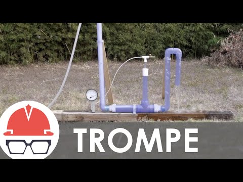
Trompes are one of the earliest air compressor devices, they were originated back in the iron ages and used mainly for providing air for forges2. Simply put, a trompe is a system that uses the energy from water falling down a tube/shaft to pressurize air coming into that same shaft from the atmosphere. Here’s a picture showing the general design:

Here’s an excellent video that talks about their history and shows how they work:
While trompes have long been abandoned for more modern technologies, they could still be used today. We explore their design and use it with the following sections.
This section includes:
- How a Trompe Works
- Uses for a Trompe
- Trompe Pros and Cons
- Trompe Design Details
- DIY Trompe Tutorial
- Trompe Cost Structure Example
- Trompe References
HOW A TROMPE WORKS
- Water flows down a vertical pipe, carrying air from the atmosphere
- The air bubbles formed within the water are compressed as they travel along the vertical pipe due to the weight of the water above it – the technical term for this is hydraulic head
- The water-air mixture then flows into a horizontal pipe and, because the air bubbles are less dense than water, they rise to the water’s surface
- Compressed air that has escaped the water is stored in a tank for use
- Water without the air is discharged upwards, out of a vertical exit pipe
USES FOR A TROMPE
Aside from the original use for providing a constant supply of air to forges, there are many other uses for the pressurized air produced by trompes which include3:
- Operating farming equipment: Good examples of this are water pumps, crop sprayers, tractors, product conveyors, and agricultural machines4.
- Pneumatics/Air Tools: Compressed air provides the energy necessary for these tools to operate. The most applicable examples for a project like ours would be nail guns, pneumatic drills, and hammers.
- Crop irrigation: Aquaponics structures could use the compressed air for aeration. During freezing weather conditions, pressurized air is also used to blow-out all water and debris out of all the irrigation system components5.
- Wastewater aeration: The process of adding air into wastewater to initiate the biodegradation of pollutants in the water. Aeration is important because the air provides the microbes the oxygen they need to survive so they can treat the water by degrading pollutants6.
- Greenhouses: Excessive temperatures inside a greenhouse will negatively impact plant growth7, the cool, clean, and compressed air produced from trompes can be used to provide airflow and cooling for the greenhouse.
- Lifting water: Compressed air can be used to lift water out of a sump or well8. The compressed air is fed through a nozzle into the water to form a froth (mixture of air and water); mixing air with water causes the froth to have a smaller density than pure water. Differences in density between the froth mixture and pure water is manipulated to allow the froth to float8 and thus water is being lifted.
- Mining: It is extremely dangerous for methane gas to build up in a mine for two reasons: static-electric spark ignition and inhalation by mine workers. Properly installed compressed air systems can be used to extract methane gas from mining environments via the use of vacuum pumps and blowers9. Other mining uses for compressed air include: blasting, material handling, ventilation, and cleaning.
- Any other reasonable application of pressurized air: Here’s a resource
PROS AND CONS
The pros and cons of trompes as a system, are summarized in the table below:

DESIGN DETAILS
These are the design specifications for the trompe system pictured below. For the minimum design criteria/dimensions needed to build a working trompe, see the DIY tutorial in the next section.

Trompe Design Diagram – Click to open the source presentation
- Intake: This consists of a 6″ diameter inlet and 4″ vertical down pipe that the water and air enter through. The entrance of the pipe is made larger than its main body because it increases the suction of air into the pipe via the venturi effect12. The venturi effect13, simply stated, is the decrease in pressure of a fluid when the cross-section of the pipe it flows through reduces. This “constriction pipe elbow” produces decreased fluid pressure and causes the extra suction in the pipe, this is needed to draw air into the system.
- Air Intake: 4” diameter air head that allows air to be drawn into the system through 0.5” diameter air injection tubes.
- Horizontal Pipe: The pipe that is connected to the intake, outflow and separation chambers.
- Separation: 6” diameter horizontal pipe that acts as a separation chamber for the air to escape out of the water into the 2 air chambers 6” in diameter where the compressed air is stored.
- Compressed Air Line: Passage in which the stored air can flow through to be used14.
- Outlet: 4” diameter outlet pipe that discharges the pure water at a level lower than the initial intake of water. Ideally, there should be a minimum of 4 feet of the head between intake and outflow11.
DIY TUTORIAL AND COST ESTIMATION
Here we present two DIY trompe examples. The first is a smaller-scale design that uses a 5-gallon cooler as an air chamber to collect separated air.The second is a larger-scale 4-inch trompe, featuring a dual air chamber configuration. Both examples are accompanied by detailed tutorials, which include the materials required, step-by-step instructions, and cost estimations.
DIY TROMPE EXAMPLE 1
The image here shows this home-made trompe. The materials required and assembly steps below are what we’d consider as the bare minimum to construct a DIY trompe. Reduction of any of the dimensions and/or removal of any parts could result in failure of the system. Unfortunately, the original tutorial for trompe construction is no longer available, but you can still follow the instructions provided below for guidance on building the system.
MATERIALS
- 1 x 1/2” diameter 50” long intake pipe
- 2 x 1” pipe (32” & 40” lengths for horizontal and outlet pipes)
- 10 x 0.28” drinking straws, sealant, duct tape (precautionary), standard drill, 5-gallon (11” diameter) cooler
- 1 x 1” 90-degree pipe elbow (to attach the horizontal and outflow pipes)
- 1 x 1” 45-degree pipe elbow (inserted at the end of the outflow pipe)
- 2 x 1/2” x 1” 90-degree pipe elbows (one for the constriction pipe and one to attach the horizontal and intake pipes) See image below:

DIY Trompe Model – Click to open source page
STEPS
- Drill 5 to 9 x 0.28” diameter holes into the pipe elbow
- Join the constriction pipe elbow (This pipe elbow has a larger diameter at its top compared to the end part where it connects to the main intake pipe. This change in diameter is the ‘constriction’ that causes the air suction aka venturi effect) to the top of the intake pipe
- Insert the intake pipes (or straws) halfway down the holes in the pipe elbow
- Drill a 1” hole through the cooler, near the bottom
- Drill evenly spaced 0.28” ‘through’ into the horizontal pipe along its length
- Insert the horizontal tube into the cooler and insert an intake pipe/straw into one of the end holes in the horizontal pipes (this acts as a splash plate)
- Apply sealant at both ends the horizontal pipe comes out of the cooler to prevent water leakage
- Attach the intake and outflow pipes to the horizontal pipe using the pipe elbows
See the above image for what this finished trompe system should look like.
COST ESTIMATION
Below is the cost estimation table for the Trompe system in Example 1. The estimation is based on the materials and tools listed previously. The actual cost may vary depending on any adjustments made to the system based on site-specific conditions.
 - Click to open the source spreadsheet")
Trompe Cost Analysis Table (Example 1) – Click to open the source spreadsheet
DIY TROMPE EXAMPLE 2
The source of this dual air chamber trompe example is the report “TROMPE: From the Past Will Come the Future,” which explores various configurations to identify the most efficient trompe systems. The trompe assembly process follows the 4-inch trompe layout provided in Appendix K.1-K.4 of the report. Additionally, the report includes 2-inch and 3-inch trompe configurations, offering alternative design options for different system requirements.
 
MATERIALS
Headpiece (Inlet & Air Inducer):
- 6” PVC pipe; 4” PVC pipe; 2” PVC pipe
- 1 × 6”×4” bushing (spigot)
- 1 × 4”×2” coupling (spigot)
- 2 × 2” street elbow
- 1 × 2” male adapter (spigot×thread)
- 1 × 2” female adapter (thread×thread)
- fiberglass resin
- 17 × 0.5” CPVC tubing
- 1 × 6” flush cleanout plug
- 1 × 6” tee
Separation & Air Chamber:
- 6” PVC pipe; 2” PVC pipe
- 2 × 6”×4” bushing (spigot); 2 × 4”×2” bushing (spigot)
- 2 × 6”×4” coupling (spigot)
- 2 × 2” street elbow; 2 × 4” street elbow
- 2 × 6” tee; 1 × 2” tee
Outlet:
- 4” PVC pipe
- 1 × 4” elbow

“4” Trompe Layout – Click to open source
STEPS
- Cut and prepare PVC pipes.
- Use fiberglass resin to glue the 0.5” CPVC tubing into a 4” × 2” coupling (spigot) as air inducer.
- Assemble the headpiece components, including the air intake, air inducer, water source inlet, and downpipe, following Appendix K.4.
- Assemble the Separation Unit using two 6” PVC tees and a 6” PVC pipe, and the Air Chamber, which consists of two 6” PVC pipes linked by 2” PVC pipes. Follow Appendix K.2 and join them with the appropriate fittings.
- Attach the downpipe to the separation unit using a 4″ street elbow connected to a 6″ x 4″ bushing spigot. (the diameter change creates a “constriction” that generates air suction, known as the venturi effect.)
- Use a 4” PVC pipe for the up pipe and outlet, attaching it to the opposite side of the separation unit. If needed, incorporate a 4” elbow to complete the outlet configuration for optimal water flow.
- Ensure that all PVC joints and connections are securely fitted and watertight.
COST ESTIMATION
Below is the cost estimation table for the 4-inch Trompe system in Example 2. The cost estimation is based on the minimum required lengths for pipes. Actual costs and pipe lengths may vary depending on site-specific conditions. In contrast to the first system, this one incorporates a dual air chamber configuration, as recommended in the report for enhanced air capture efficiency. Additionally, the system is larger and uses wider diameter pipes, which are more expensive than the smaller pipes in the first system. As a result, the material cost of this system is much higher than that of the first example.
 - Click to open the source spreadsheet")
Trompe Cost Analysis Table (Example 2) – Click to open the source spreadsheet
KEY DESIGN CONSIDERATION AND ONLINE RESOURCES FOR TROMPE SYSTEM
Based on insights from report resources, several key considerations must be addressed when designing a trompe system to ensure optimal performance. The outlet pipe should not exceed 70% of the inlet pipe’s length to prevent siphoning issues. The driving head, which is vital for generating pressure, works best at around 4.0 feet but can still compress air with a minimum of 2.9 feet. For efficient air collection, it is recommended to use dual air chambers: one near the inlet and a larger vertical chamber near the outlet to capture air effectively.
Additionally, numerous trompe tutorials are available online. For example, the YouTube video “How To Build A Trompe – An Air Compressor Without Moving Part” offers practical demonstrations and insights. It also discusses the potential flexibility of trompe designs based on site conditions. For instance, the previously discussed cases all feature linear designs that offer simplicity, while a more compact design with the air compression port inside the water chamber can save space and reduce system length. Balancing these factors will allow for a highly adaptable and efficient trompe system. For more detailed instructions and visual guidance, be sure to visit the source report and video to enhance your understanding of the trompe construction process.
TROMPE COST STRUCTURE EXAMPLE
TROMPE REFERENCES
Trompe Cost Analysis Table (Example 1)
Trompe Cost Analysis Table (Example 2)
The following are the superscript references numbered in the section above.
- Wikipedia: “Trompe”
- Article: “The Hydraulic Air Compressor – a brief history”
- Article: “Agriculture Compressors”
- Article: “A Guide to the Best Air Compressors for Agriculture & Farming”
- Article: “Winterization Using Air Blow Out”
- Article: “Why is Aeration Important for Wastewater Treatment?”
- Article: “Ventilation for Greenhouses”
- Article: “Air-Lift Water Pumps ” Sustainable Engineering for Electricity-Poor Areas”
- Article: “Compressed Air Usage in the Mining Industry”
- Article: “Why do bubbles rise to the surface?”
- PDF Download: “Trompe – The Oldest Technology You Never Heard Of”
- Article: “Science of the Trompe”
- Article: “What Is the Venturi Effect?”
- Article: “Harness Hydro Power with a Trompe”
- Article: “TROMPE: From the Past Will Come the Future
- Youtube Video: “How To Build A Trompe – An Air Compressor Without Moving Parts
RAM PUMPS
A ram pump is a device that uses the momentum of large amounts of falling water to pump a smaller amount of water upwards1. The system operates automatically, with only two moving parts: a delivery valve and a waste valve2. We discuss ram pumps here with the following sections:
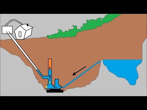
HOW A RAM PUMP WORKS
The best explanations we’ve found for how a ram pump works are the following two videos.

- Water from an elevated height flows through an inlet pipe and expelled out through the open waste valve into the environment
- The speed built up by the water flow eventually causes a pressure drop around the waste valve, closing the valve
- Pressure builds up in the inlet pipe causing the delivery valve to open
- The pressurized water now flows up through the delivery pipe and some is stored inside an accumulator (air chamber that stores some of the pressurized water)
- Once water flows back from the waste valve, it re-opens and the delivery valve closes, thus restarting the entire process
- Compressed air at the top of the accumulator can push water through the delivery pipe whilst the delivery valve is closed
As earlier mentioned, ram pumps are used to transport water to heights above its source by using the potential energy of falling water; the minimum height drop of water needed for the pump to work is around 20 inches2. For every 1 foot of head (water drop), you can lift the water up to 7 feet; this is a conservative approximation3. There is virtually infinite potential for how long the delivery pipe can transport water e.g. 5km.
A big issue with these systems though is that only 10% of the water flowing through the ram is pumped by the delivery pipe, with the rest being dispersed out of the system. If the ram pump is situated at a pond or river, then the dispersed water can potentially return to its original source. Other use options for the waste water could possibly make this more sustainable too.
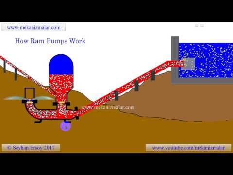
Examples of applications ram pumps can be used for are: feeding water into a household, agricultural irrigation, and sewage treatment. See below an insightful diagram from here and explaining the entire process.

How Ram Pump Works Diagram – click to go to source
Here is a table summarizing the pros and cons of a ram pump.

Pros and Cons of a Ram Pump System – Click here to open the source spreadsheet
DIY RAM PUMP
Provided below is a summary of the DIY process for constructing a ram pump system. All the resources needed can be sourced from Home Depot and cost approximately $100 (USD). For the source of the design below, we strongly suggest visiting this “Hydraulic Ram Pump” Instructables article. The following is just a photo of the design but the source page contains complete instructions.

Hydraulic Ram Pump DIY tutorial – Click to open the source website
The construction steps can be summarized as follows:
- Cut segments off of the stock 1-1/4″ pipe that are long enough to reach fully into the fittings with a hacksaw and use sandpaper to smooth the inside edges of the pipes.
- In a well ventilated area, apply a 2” wide coat around the outer edge of the pipes and the inner edge of the fittings you want to join; repeat the same process using cement over the primed surfaces then lastly, join the pipe and fittings (clamp them so the pipe doesn’t slide back).
- Assemble the front and back sections of the main line (wrap Teflon tape around the threads before joining them to avoid leaks).
- Assemble the pressure chamber. Pump the bike tube until it is squishy, then insert it into the big pipe pictured below. Cement both ends and clamp the assembly up until the cement dries; lastly, glue the pressure chamber to the pipe coming from the main tee (right picture beneath).
- Assemble pressure gauge section (optional) to the main tee. Cutting the ¾â€™â€™ x 6” pipe in half is required to complete this step. End result is shown below:
- Install the brass swing check valve; the flapper should be hanging down whilst the rest of the ram pump unit is upright.
- Attach the stand pipe to the 1-¼â€™â€™ union with cement and then hook the other end to the source of water using a shower drain which is attached to a styrofoam cooler.
Visit original source http://www.instructables.com/id/Hydraulic-Ram-Pump/ for assembly pictures, cost analysis details, troubleshooting, improvements to the design and more.
RAM PUMP REFERENCES
The following are the superscript references numbered in the section above.
- Article: “How does a hydraulic ram pump work?”
- Article: “Ram Pumps – How They Work”
- Article: “Hydraulic Ram Pumps”
- Article: “Power to the Mines”
TROMPE & RAM PUMP COMBINATION
In this section, we shall explore the use of a trompe and ram pump as one system so that we can collect pressurized air whilst pumping water. Several questions come to mind when attempting to devise such a system: Is it more efficient to run the systems separately? Is water flow at the output of the trompe fast enough to initiate the water ram effect? Will it even work?
Thankfully, there is a YouTube video demonstrating this system in action. Here it is and below the video we its contents:

Water Powered “Air Compressor and Water Pump”. – Click to open the YouTube video.
Summary:
- Ram intake/trompe output should be at least 3 ft. lower than the trompe water intake (@ elbow).
- There should be a larger trompe intake pipe than the outflow pipe. This is so that more air can be taken into the system without having the air intake too far uphill because the water ram effect will stop the flow and let air bubbles travel backward up the intake pipe stream if the air intake is too uphill.
- Once the upper cylinder is full of air and the pressure is greater than that of the cylinder, the one-way valve between both tanks shuts to avoid the higher pressure in the upper tank blowing out onto the lower pressure in the lower tank, pushing the water and making us lose the stored energy.
- The ram effect pushes more air up into the storage cylinder compared to using just the trompe.
- Swing check one-way valve is used at the output.
OPEN SOURCE CONTENT TO BE ADDED LATER
Once on the property, One Community will open source project-launch blueprint the complete process of installing and maintaining any hydro-energy infrastructure we end up using. We will do this for everything we think will be helpful for those replicating our system(s) as part of the One Community complete open source self-sufficient teacher/demonstration community, village, and/or city model. Upcoming resources will include:
- Layperson’s guide to purchasing all equipment
- Layperson’s guide to working with your county
- Layperson’s guide to installation
- Layperson’s guide to maintenance and upkeep
- Energy production details
- Lessons learned during setup and ongoing use/maintenance
- Use this page (click here) if you have a guide/tutorial you’d like to suggest be added here
RESOURCES
The following are resources we found relevant and helpful. This includes all the resources included in the reference sections above as well as additional ones.
- Article: “The Trompe – An Almost Forgotten Air Compression System”
- Trompe Article: “Power to the Mines”
- Hydro-power Definition | Hydro-power Definition
- Article: “How do hydro systems work?”
- Article: “Small Hydropower Systems”
- Article: “Types of Hydropower Turbines”
- Article: “Impulse Turbine”
- Article: “Hydro Power Cost Analysis Article”
- Article: “Costs Associated With Hydroelectricity”
- Article: “Hydropower Costs | Renewable Energy Hydroelectricity Costs Vs Other Renewable & Fossil Costs”
- Article: “Energy Technology Systems Analysis Program”
- Wikipedia: “Trompe”
- Article: “The Hydraulic Air Compressor – a brief history”
- Article: “Agriculture Compressors”
- Article: “A Guide to the Best Air Compressors for Agriculture & Farming”
- Article: “Winterization Using Air Blow Out”
- Article: “Why is Aeration Important for Wastewater Treatment?”
- Article: “Ventilation for Greenhouses”
- Article: “Air-Lift Water Pumps ” Sustainable Engineering for Electricity-Poor Areas”
- Article: “Compressed Air Usage in the Mining Industry”
- Article: “Why do bubbles rise to the surface?”
- PDF Download: Trompe – The Oldest Technology You Never Heard Of
- Article: “Science of the Trompe
- PDF Download: Trompe”The Oldest Technology You Never Heard Of”
- Article: “Science of the Trompe”
- Article: “What Is the Venturi Effect?”
- Article: “Harness Hydro Power with a Trompe”
- DIY Article: “Researching the Trompe: Creating a Model”
- Article “TROMPE: From the Past Will Come the Future”
- Youtube Video: “How To Build A Trome – An Air Compressor Without Moving Parts
- Article: “The Trompe – An Almost Forgotten Air Compression System”
- Forum: “Hydraulic Ram Pumps on Permies.com”
- Youtube Video: “how ram pumps work?”
- Youtube Video: ” Water Powered ‘Air Compressor and Water Pump’. The ‘Trompe Hammer’, Trompe and Water Ram”
- Use this page (click here) if you have a resource you’d like to suggest be added here
Here are some extra related videos that we found interesting:

![Trompe Animation [PDC preview]](https://onecommunityglobal.org/wp-content/plugins/wp-youtube-lyte/lyteCache.php?origThumbUrl=https%3A%2F%2Fi.ytimg.com%2Fvi%2FypPo3B8nPUU%2F0.jpg)


Use this page (click here) if you have a resource you’d like to suggest be added here
SUMMARY
All the hydro-power systems on this page have useful applications. Micro hydro-power systems are probably the most practical though. Trompes are environmentally friendly and very useful devices for obtaining pressurized, cool and dry air without the use of moving parts, but there are limited uses for pressurized air. Ram pumps have only two moving part and can elevate a small percentage of water but the rest is wasted in most cases. Because of this waste, we’d say pressurized air has a wider variety of applications compared to the uses for small percentages of water that could be elevated. Putting a trompe and ram pump together is possible but not very useful due to their different applications and low efficiency. The only benefit we found in combining them is that the ram pump effect can be used to allow more air and a higher pressure to be achieved in the storage tank of a trompe.
FREQUENTLY ANSWERED QUESTIONS
Q: For small-scale use, what would you say would be the best/most practical use of a DIY trompe?
A rechargeable air compressor can be purchased for less than the cost of the DIY trompe described on this page. That said, nonstop aeration of an aquaponics or large-scale fish tank is a useful application. Check out this video of a system using a trompe for this:

Q: For small-scale use, what would you say would be the best/most practical use of a DIY ram pump?
If you have a reliable source of water, a ram pump is an amazing way to move water from a low point to a high point. If wasting water is not something you wish to do, you can buy a small rechargeable or electric water pump for less than the cost of the DIY ram pump version described on this page. It would require power but not waste water.
Q: How does One Community plan to implement trompes?
If we decide to implement trompes, we think air conditioning applications and water aeration would be the most likely uses.
Q: Does One Community plan to implement ram pumps?
As of right now, there is no plan to implement them due to the excessive amounts of water wasted.
![]()