 One Community
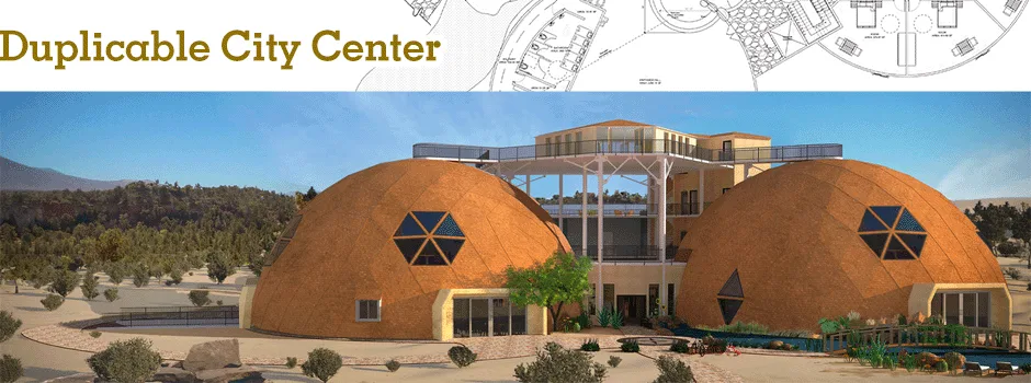
Duplicable City Center Heating and Cooling
This page is about the development of the heating and cooling plan for the Duplicable City Center®. It is purposed to share the specifics of the design, implementation, and maintenance of the complete City Center HVAC and its integration with the automation, monitoring, and control systems.
We discuss this with the following sections:
- What is Sustainable Heating and Cooling
- Why Open Source Heating and Cooling Design
- Ways to Contribute to this Open Source Component
- Key Consultants to this Component of One Community
- Eco-HVAC Design Details
- Applying LEED in the Duplicable City Center (Case Study)
- Resources
- Summary
- FAQ
NOTE: THIS PAGE IS NOT CONSIDERED BY US TO BE A COMPLETE AND USABLE TUTORIAL UNTIL
WE FINISH OUR OWN CONSTRUCTION OF THIS COMPONENT, CONFIRM ALL THE DETAILS, AND ADD
TO THIS PAGE ALL THE RELATED VIDEOS, EXPERIENCE, AND OTHER UPDATES FROM THAT BUILD.
IN THE MEANTIME, YOU CAN HELP US COMPLETE IT ALL SOONER WITH THE FOLLOWING OPTIONS:
INPUT & FEEDBACK | JOIN OUR TEAM | HELP US BUY THE PROPERTY
RELATED PAGES

![]()
")
![]()
![]()
")
")
")
WHAT IS SUSTAINABLE
HEATING & COOLING
![]() The simplest definition of “sustainable heating and cooling” could arguably be heating and cooling that is powered by renewable energy. This approach can be made even more sustainable by integrating passive approaches like careful window placement for non-mechanical heating and venting, use of thermal mass, etc. Design choices like maximally energy efficient windows and doors, choice of insulation, and the air-circulation benefits of domes over square buildings also contribute. In addition to these, we will objectively measure and improve the sustainability of the City Center HVAC system using the open source control and automation systems we’re designing. We will open source all the data we gather, everything we learn, and our ongoing modifications and evolutions to help others to more easily learn from, replicate, and/or improve these designs.
The simplest definition of “sustainable heating and cooling” could arguably be heating and cooling that is powered by renewable energy. This approach can be made even more sustainable by integrating passive approaches like careful window placement for non-mechanical heating and venting, use of thermal mass, etc. Design choices like maximally energy efficient windows and doors, choice of insulation, and the air-circulation benefits of domes over square buildings also contribute. In addition to these, we will objectively measure and improve the sustainability of the City Center HVAC system using the open source control and automation systems we’re designing. We will open source all the data we gather, everything we learn, and our ongoing modifications and evolutions to help others to more easily learn from, replicate, and/or improve these designs.
Here is the floor plan overview:

Duplicable City Center HVAC Design Floor Plan – Click to enlarge (2.3 MB) in a new window
Here are the zone specifics:
 in a new tab")
HVAC Zones Overview – Click to open DropBox image (1.1 MB) in a new tab
Here is the wall insulation plan overview:

Duplicable City Center Insulation Plan Overview – Click to enlarge (1.8 MB) in a new window
WHY OPEN SOURCE
HEATING & COOLING DESIGN
![]() Heating and/or cooling in most climates is a significant and important consideration due to the associated energy requirements and design and equipment needs. Our goal in open sourcing the Duplicable City Center HVAC designs, window and door research and installation, insulation decisions, and automation, monitoring, and control systems is to provide useful data for:
Heating and/or cooling in most climates is a significant and important consideration due to the associated energy requirements and design and equipment needs. Our goal in open sourcing the Duplicable City Center HVAC designs, window and door research and installation, insulation decisions, and automation, monitoring, and control systems is to provide useful data for:
- Replication
- Improvement
- Global collaboration and sharing
- Academic interest and reference
This open source aspect of the City Center will additionally contribute to our global-change methodology by functioning as a testing space for HVAC-related equipment and lifestyle changes. Through use of the extensive automation, monitoring, and control systems designed into this building, we’ll be able to objectively gather, compare, and share thousands of data points related to any modifications we choose to implement and/or test.
WAYS TO CONTRIBUTE TO THE CITY CENTER HEATING AND COOLING DESIGN
SUGGESTIONS | CONSULTING | MEMBERSHIP | OTHER OPTIONS
KEY CONSULTANTS TO THE CITY CENTER HEATING AND COOLING DESIGN
Adrienne Gould-Choquette: Mechanical Engineer
David Olivero: Mechanical Engineer & Data Scientist
Falgun Patel: Mechanical Engineer
Ian Oliver Malinay: Mechanical Engineer, Master Plumber, True Advisor and LEED AP BD+C
Vamsi Pulugurtha: Mechanical Engineer
ECO-HVAC DESIGN DETAILS
 Climate control design in the City Center represents simultaneously one of the greatest potential energy expenditures, and also one of the greatest opportunities to save energy. To maximize our design’s efficiency and sustainability, our design approach was to leverage the criteria put forth by LEED to rate building design for energy thriftiness. Below, we breakdown and discuss the complete design process with the following sections:
- Understanding R-value and U-value
- Base Equipment Selection Criteria
- Standard vs. High-Efficiency City Center Comparison
- Calculating Thermal Mass
- Indoor/Outdoor Pool Considerations
- Defining Zones and Calculating Loads
- Eco-HVAC Design & LEED
- Applying LEED in the Duplicable City Center (Case Study)

Duplicable City Center Kitchen: One of the Largest HVAC-use Areas – Click for the open source hub
UNDERSTANDING R-VALUE AND U-VALUE
Before getting into the design specifics, it is helpful to understand R-value and U-value. R-value is the capacity of an insulating material to resist heat flow. The higher the R-value, the greater the insulating power. U-value, also known as Thermal transmittance, is the rate of transfer of heat through a structure. This can be a single material or a composite and the graphic below shows the relationship of U-value to R-value. The lower the U-value the better.

BASE EQUIPMENT SELECTION CRITERIA
Having established goals and a plan for the Duplicable City Center‘s R-value and U-value, the next step of our design process was to think about the design criteria for equipment selection. The efficiency of an HVAC device can be characterized in terms of its Seasonal Energy Efficiency Ratio value (a.k.a. SEER). In summertime, SEER is a way of comparing how much cooling a system puts out divided by the amount of electrical energy it takes to run it. Put plainly, the higher the SEER value, the more heating/cooling can be accomplished for a given energy expenditure (i.e., greater efficiency).
For the purposes of this design, it was decided to employ only devices that could achieve SEER ratings close to 20, or even greater. We committed to this level of equipment efficiency because of how efficient the rest of our building was. A consequence of this decision though is that it eliminated the vast majority of commercial HVAC equipment from consideration, due to the much lower SEER ratings of even relatively efficient equipment of this type. Most commercial HVAC equipment have SEER values of 11 to 14, which we did not consider efficient enough. A modern form of heat pump known as a “ductless minisplit” was selected instead. The diminutive size and highly engineered design of ductless minisplits allow SEER values in the 18 to 22 range.
After much research and choosing the ductless minisplit, a third engineer tasked with completing the designs suggested a Variable Flow Refrigerant system may be better. To determine if this was true, we put a 4th engineer on the task of comparing them. This engineer was not attached to the outcome of the research, so we considered his conclusion the most objective choice. His complete research process is below.
DUCTLESS MINISPLIT VS. VARIABLE FLOW REFRIGERANT SYSTEM
Like standard air-source heat pumps, mini splits have two main components: an outdoor condenser and an indoor evaporator unit. A conduit is used to link the outdoor and indoor units, this houses the power cable, refrigerant tubing, suction tubing, and a condensate drain.
According to Energy.gov, the main advantages of minisplits are their small size and flexibility for zoning which means that individual rooms can be heated or cooled. This is because most mini-split outdoor units have the capacity to be connected to up to four or more indoor evaporator units, these evaporator units can be regulated individually. Ductless mini-split systems are also easy to install because of the flexible conduit. The conduit generally only requires a hole in the wall of 3 inches, which makes it also aesthetically pleasing. The flexibility of the conduit means that the outdoor unit can be located up to 50 ft from the indoor evaporator units with more interior design options, the indoor units could be suspended or mounted flush on a ceiling or wall. Another advantage of using the mini-splits is that duct losses (which can account for up to 30% of energy consumption for space conditioning) are avoided.
The main disadvantages of using mini-split systems are more hardware is required (see below) and there are less experienced installers for these systems. This means higher installation and maintenance costs.
VRF systems can be thought of as an enhanced version of ductless minisplits and promise a more energy-efficient strategy for commercial buildings, but usually at a somewhat higher cost. VRF systems use heat pumps or heat recovery systems to provide powerful heating and cooling for all indoor and outdoor units without the use of air ducts. With a VRF system, a building can have multiple indoor units utilized by a single outdoor condensing unit, either with a heat pump or heat recovery system. The main difference between the two is that the latter can provide simultaneous heating and cooling when used in a heat recovery configuration. The outdoor unit has compressors with inverter-driven fans, which means their speed varies by adjusting the frequency of the power supply. When the indoor unit sends a demand to the outdoor unit, the outdoor unit delivers the specific amount of refrigerant to the individual indoor units.
VRF technology can perform at a high capacity without the use of ducts too, which is one of its many advantages. VRF systems continually adjust the flow of refrigerant to each indoor unit. The control is achieved by continually varying the flow of refrigerant through a pulse modulating valve (PMV) whose opening is determined by the microprocessor receiving information from the thermistor sensors in each indoor unit. The indoor units are linked by a control wire to the outdoor unit which responds to the demand from the indoor units by varying its compressor speed to match the total cooling and/or heating requirements.
Here’s an example of a VRF system:

Example of a VRF System
VRF systems in commercial buildings are typically more efficient than mini-splits because they (not in our case) minimize the refrigerant path. In the mini-split multi-zone system each indoor unit is connected to the outdoor unit with separate conduit pipes while the VRV/VRF systems use a main conduit pipe with separation tubes and headers to maintain different refrigerant flow rates going into the various indoor units. Here’s a typical example showing this.

Multi/Mini-split to VRF Refrigerant Piping Comparison
So VRF offers energy savings through part-load efficiencies (the ability of a system to handle part-load energy use so that it can deliver the exact load requirement with the minimum power input), heat recovery, and reduced duct losses. Annual energy savings with VRF are dependent on the climate with some regions getting energy savings above 30% but a conservative energy savings estimate of 20% is considered. According to research done by EES Consulting, the installed cost of VRF systems is about $18 per square foot of conditioned space. It was also calculated that a VRF system installed in a new construction would pay for itself after about 16 years.
CITY CENTER CASE STUDY
Ultimately, due to the efficiency benefits due to the footprint and shape of our building, and the lesser costs, the minisplit multi-zone setup was considered more suitable. This table summarizes our analysis.

Most Viable HVAC System for the City Center Minisplit vs VRF
Samsung VRF units were considered while Mitsubishi minisplit units were considered, both systems have very good feedback from users about the high level of comfort, quietness, and efficiency of both systems, but the Samsung Mitsubishi systems were more efficient. The SEER (Seasonal Energy Efficiency Ratio) values for the VRF outdoor evaporator efficiency is about 17, which is less than the SEER of the individual outdoor minisplit condensers which are in the range of 18.9 to 20 (see above).
The minisplit system also works very well with the Duplicable City Center because of the ability to place multiple outdoor units where needed. They can be positioned on the walls or on the ground and, since multiple outdoor units are used, significantly less refrigerant piping is needed. The spread-out nature of the three domes would mean very long refrigerant pipes for the VRF system, resulting in losses in efficiency and higher maintenance costs. Additionally, the minisplit system does not interfere with the ERV ducting but the VRF piping would have to be designed to maneuver around the ERV ducting on the first floor.
As seen from the simplified diagrams below, the Duplicable City Center would need 13 outdoor minisplit condensers to operate all the indoor evaporator units. While it would only need three VRF outdoor evaporator units to remain below the maximum refrigerant piping lengths.

Simplified Diagram to Show the Minisplit System Distribution in the Duplicable City Center
The total cooling load required by the building is about 366k BTU/hr and the total capacity of the indoor evaporators is 645k BTU/hr. The total capacity of the corresponding Mitsubishi outdoor minisplit condensers is 447k BTU/hr. An equivalent outdoor VRF unit set up is a combination of three 18 HP Samsung DVM-S outdoor VFR units which combined would have a capacity of about 516k BTU/hr which is close to the total capacity of the of the outdoor minisplit condenser units.
If it were crucial for the building to have zones which can be simultaneously cooled and heated though, the VRF system would be better because only the VRF system could achieve that. A fault with a single VRF outdoor unit would affect the functionality of many indoor evaporator units and would affect the comfort of many people though. While a fault with an outdoor minisplit condenser would only affect a few indoor evaporator units. On the other hand, maintenance would be easier for the VFR system because there are only three outdoor evaporator units to be maintained, two of which are housed in the same location. The 3rd would be on the 4th floor.
 System Distribution in Duplicable City Center")
Simplified Diagram to Show Variable Refrigerant Flow (VRF) System Distribution in Duplicable City Center
Regular maintenance is important for the optimum performance of both systems. There is minimal work to be done on the outdoor units of both the VRF and minisplit systems, but since the VRF has fewer units, less time would be needed for maintenance of the VRF outdoor units. Checking refrigerant piping to identify and repair leaks is part of the maintenance process too though, and the much longer length of refrigerant piping for VRF systems, and more difficult process of checking these pipes, negates the advantage of having fewer outdoor units to maintain.
The base price of the outdoor minisplit condensers is about $42,320 while the total price for the outdoor units for the VRF system is about $41,170. Assuming that the same indoor units are used for both systems, the costs of the two systems can be seen as almost equivalent. These prices though are estimates based on the listed costs on supplier websites and do not take shipping costs into account. They also don’t take into account installation costs.
The cost of installing the minisplit system is estimated to be $75,000 based on a labor cost of $2028 per ton obtained from a report by Northeast Energy Efficiency Partnerships (NEEP). The cost of installing the VRF system depends on the configuration, heat pump configuration would cost about $80,000 while the heat recovery configuration would cost about $128,000. These figures are also estimated from data obtained from the NEEP report.
These increased costs and the overall increased efficiency of the minisplit multi-zone setup made it the better choice for the Duplicable City Center.
STANDARD VS HIGH-EFFICIENCY CITY CENTER COMPARISON
Next we wanted to assess the impacts of maximizing the efficiency of each of the other City Center elements that would affect HVAC design and efficiency. The Duplicable City Center has a few unique characteristics: a root cellar, server rooms, an indoor pool, and it is comprised of three geodesic domes. This section shares the calculations we completed comparing standard versus high-efficiency design details. This comparison includes an R-45 insulation for the exterior surfaces of the domes and building insulation, equipment loads, and people loads remaining constant. Two heat load calculations were performed:
- A baseline load using International Energy Code minimums and ASHRAE Fundamentals default materials
- And a high-efficiency (HE) version of the City Center. The HE version included the following changes:
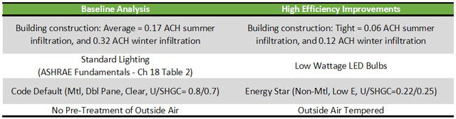
Note: The benefits outlined below are just analyzing the effect on the heating and cooling systems. The benefits to building efficiency have much farther reaching benefits. For example, switching to LED lighting from regular incandescent lighting. Incandescent bulbs put off more heat than LED bulbs. This heat is a form of wasted energy which causes increased demand on the cooling system in the summer. By switching to LED bulbs, the reduced heat load to the building means lower cooling costs in the summer and this translates into a smaller capacity cooling system too. In addition to this, the bulbs lower power consumption means less energy requirements, which all means a more comfortable building powered by a smaller array of photovoltaic panels.
BUILDING CONSTRUCTION
A big part of building efficiency is the “tightness” of the building, which is a measure of leakage and airflow though things like outlets, light fixtures, window framing, etc. A tighter building means greater temperature control. One Community’s City Center prototype building will be built in an area with temperatures averaging between 20 and 90 degrees F. The domes are designed for passive cooling during the summer months with backup air conditioning for extreme temperature periods. The winter lows can dip below zero, so during the winter, to avoid drafts, efficiently maintain comfortable temperatures, and maintain proper building air balance, a tightly constructed building is an even more critical consideration.
Building “air tightness” is improved by sealing leakage pathways. Examples of this are:
- Ensuring windows and doors are properly installed with weather stripping, sealants, gaskets, etc.
- Sealing outlets and recessed lights, which often make easy pathways between conditioned and non-conditioned spaces
A source for more information on this is found in the Building Technologies Program Air Leakage Guide from the US Department of Energy.
Below are the results of One Community’s City Center prototype building comparing an “average building” (a maximum of 0.17 air changes per hour (ACH) in the summer and 0.32 ACH in the winter) to a “tight building” (a maximum of 0.6 ACH in the summer and 0.12 ACH in the winter).
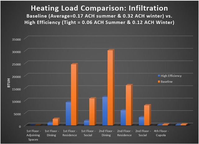
What you see is properly sealing the building makes a significant impact on the results of the heating load calculation. It cuts the impact of outside air infiltration by over 50% for all spaces of the building.
VENTILATION
A tight building also comes along with requirement for greater attention to ventilation to ensure the comfort and health of the occupants. Two options when introducing ventilation air into a building are considered for this analysis. The Baseline method is modeled such that the fresh air directly enters the air handling unit’s return. The High Efficiency method is modeled such that the outdoor air is pre-treated to 63 degree Fahrenheit, before being introduced into the air handler.
The impact of this on the heating load is shown here:
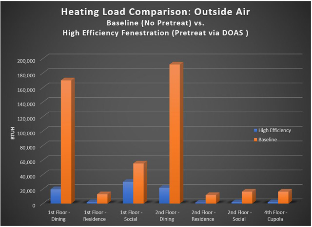
Not surprisingly, the burden on the primary heating system is significantly reduced when 63 degree air is introduced versus 8 degree air. What is not represented here is the energy and equipment needed to pretreat the air to 63 degrees. A dedicated outdoor air system (DOAS) is recommended as it is specifically designed for this functionality. A DOAS will have additional upfront maintenance and operating costs, so this data is not all savings.
BUILDING GLASS (“Fenestration” – Glass Doors and Windows)
Building glass is called “fenestration” and consists of the glass doors and windows of any structure. The glass-to-wall ratio for the Duplicable City Center was designed to be well balanced and significantly more sustainable than what is seen in many geodesic dome structures. The International Energy Code Table C303.1.3 lists default values for window specifications given their physical characteristics. The Baseline building was modeled using metal frame, clear, double glazed glass (U=0.8, SHGC=0.7).
Since the time of this writing, exact windows have not been specified, Efficient Windows Collaborative’s window selection tool was used to select windows with the following U=0.22 and SHGC=0.25.
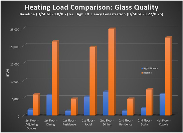
As expected, more efficient windows greatly reduce the heat loss of the building to the outdoors.
LIGHTING
The final variable used in the Baseline vs High-efficiency building comparison is lighting. As stated earlier, there are a multitude of benefits over and above HVAC equipment sizing when selecting more energy efficient light bulbs. You can read more about this on the One Community Lighting Analysis open source hub. Since lighting adds heat to the building, inefficiency in lighting burdens the HVAC systems during building cooling. Below is a comparison on the energy usage for cooling with baseline lighting as dictated in ASHRAE Fundamentals Chapter 18 Table 2 for the various spaces versus the high-efficiency building which uses low-wattage high-efficiency bulbs:

What you see above is the significant savings for the cooling load by using LED low-wattage bulbs versus traditional ASHRAE design standards.
APPLICATION
So which do we recommend implementing? ALL design changes are highly recommended. In this image you can see the difference in HVAC loads when all of the above high-efficiency options are applied together. The difference is significant enough to justify the costs associated with a more comprehensive design, so that’s what we’ve chosen.
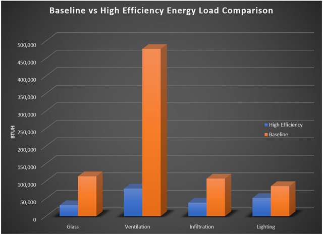
These charts give a representation of the burden each factor places on the system in non-energy-efficient (Baseline) models and High Efficiency Models.
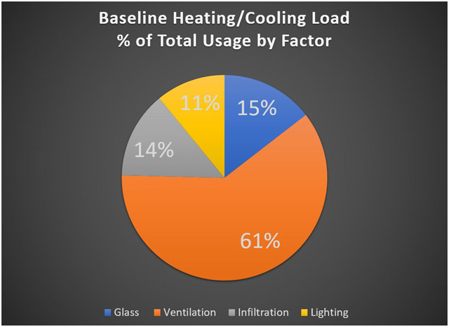
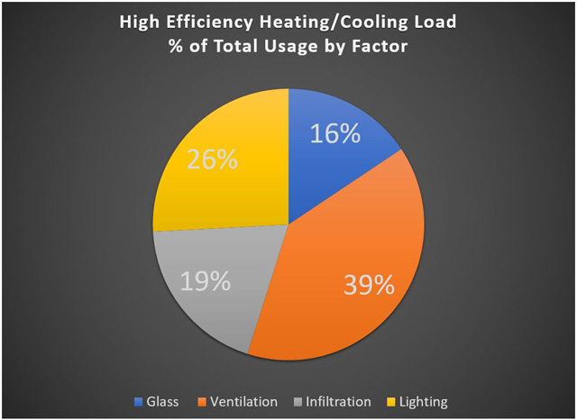
Tempering the outside air has the largest impact (and is most likely required by local building codes), but all factors show measurable and viable improvements. Implementation of all options significantly reduces total system requirements and creates a much more balanced load usage from the individual components. This saves resources, reduces equipment costs, and provides a more comfortable and consistent living experience for users.
CALCULATING THERMAL MASS
Having decided to maximize all options for efficiency, we next wanted to find out much thermal mass is in the domes. Thermal mass is the ability of a material to absorb and store heat energy. A lot of heat energy is required to change the temperature of high density materials like concrete, bricks, and tiles. They are therefore said to have high thermal mass. Lightweight materials such as timber have low thermal mass. The more you have, the slower the temperature in a building will change.
There was some suggestion initially that the thermal mass of the domes was high. A high thermal mass would suggest that passive heating and cooling, versus active strategies, could be enough. Running calculations though indicated that the thermal masses of the domes was not sufficient for fully passive strategies. Including all the Standard vs. High-Efficiency City Center Comparison data further confirmed our plan for a more traditional HVAC system using minisplits as the best choice.
Here are the initial thermal mass calculations for each dome:

City Center Thermal Mass Calculations – Click to open the spreadsheet with the most current data
INDOOR/OUTDOOR POOL CONSIDERATIONS
The City Center Natural Pool was the next major consideration. This pool is partly inside and partly outside the Social Dome. A small opening allows users to pass through the wall separating the inside pool from the outside pool. In addition to the potential for infiltration losses this open door introduces, there is also excessive moisture in summer months which will have to be removed from interior air, an additional heat loss path in winter, and the added thermal mass of the pool to consider. In addition to this, we needed to consider all the usage/comfort considerations.
We discuss here all of these in the following sections:
- Pool Challenges from the Perspective of the Building
- Pool Challenges from the Perspective of the Pool
- Pool Challenges from the Perspective of Pool Users
- Putting it all Together

Social Dome HVAC Pool Considerations – Click for the Eco-pool and Spa open source hub
POOL CHALLENGES FROM THE PERSPECTIVE OF THE BUILDING
The biggest challenge we saw with the pool was its potential impact on the building itself and our HVAC costs. The temperature we decide to keep the pool at is the contributing factor to both of these. The higher the pool temperature the more energy that will be required to maintain it. Humidity in the Social Dome will also be much higher with higher water temperatures. This means a high set-point temperature in the summer months would require a larger HVAC system to address the additional humidity.
Similar challenges are present in winter:
- Pool Heating Costs: Heating the pool in the winter will cost more than in the summer. Also, even if the access door connecting the inner and outer portions of the pool is closed in winter, significant heat loss may still occur through the wall. Replacing the door with a tunnel will improve this significantly.
- Air Heating Costs: Higher pool temps will generally necessitate higher air temps for bather comfort. Also, the warmer/colder the Social Dome air, the easier/harder it would be to maintain the pool temperature. These further increase heating energy bills.
- Air Dehumidification Needs: Moisture holding capacity of air increases dramatically with temperature. Warm pools mean more evaporation, which produces moisture that will need to be removed from the system. Dehumidification equipment in HVAC system must be sized appropriately.
- Dew Point and Condensation Risk: Higher temperatures and humidity translate into a higher dew point. Dew point is the temperature at which the existing air humidity will condense. The useful life of windows, doors, and building components are reduced by condensation. Mold growth is also increased by condensation.
POOL CHALLENGES FROM THE PERSPECTIVE OF THE POOL
As mentioned briefly above, maintaining the temperature of the pool is another challenge. The warmer we desire the pool, the more expensive it will be to maintain. Here is a graphic showing all the heat losses that need to be offset with a pool like this.

We ran calculations to better understand how big a challenge maintaining the pool temperature might be. What we calculated were the heat loss estimates through the dome/pool wall between the bodies of water inside and outside the dome. What we were most interested in was how the pool would function in the winter when we’d have the passageway door closed. To understand this we calculated how much heat the pool would be losing (in BTUs) per hour based on the temperature differences between the inside water and outside water and with various levels of insulation in the separating wall.

Pool Heat Loss Calculations in BTUs/Hour – Click for Google Spreadsheet with the most current data
What this data shows is that a wall with an R-value of at least 4 will meet our needs. We are designing for an R-value of 32+ though.
POOL CHALLENGES FROM THE PERSPECTIVE OF POOL USERS
In addition to all the challenges above, we also needed to consider the comfort of pool users. This presented some interesting tradeoffs, as shown below.

PUTTING IT ALL TOGETHER
To figure out the best strategy for our situation, a simple model was constructed to explore the heat transfer in different temperature scenarios. The three scenarios we tested are shown in this graphic.

Social Dome Pool Modeling – Click to enlarge
Scenario #3 is what we have decided to go with. In this scenario we will keep the inner and outer pool unheated in the winter and at a modest 78Ëš F (26Ëš C) in the summer. We chose this because it provided the following benefits:
- Lowest energy needs to heat the pool
- Lowest energy needs for the HVAC system
- Lowest evaporation/chance of condensation/mold buildup
- A pool that will be comfortable for most users to cool off in during warm summer days
The biggest tradeoff with this scenario though is that the pool will be cold during the fall, winter, and spring. In the winter and spring the outdoor portion will most likely be frozen. This will make the pool mostly for decorative use during these seasons. We considered this acceptable because we expect the eco-spa to be a better use of resources and preferable during these seasons.
DEFINING ZONES AND CALCULATING LOADS
Now that we’d thoroughly explored R-values and U-values, decided on minisplits, decided to go with the best insulation, sealing, doors and windows, and LED lighting, calculated thermal mass, and ran enough simulations to know how we’d address the indoor/outdoor pool, we were ready to define our heating and cooling zones and run our heating and cooling load calculations. Using standard heat load calculation software, here are those calculations:

Heating and Cooling Loads Calculations: Click for the Google Spreadsheet with the most current data

Heating and Cooling Loads Bar Charts: Click for the Google Spreadsheet with the most current data
Drilling this down further, using the zones and subzones of the electrical system as a guide, the heating and cooling loads were broken down to values for different rooms, so that the correct size minisplits could be chosen for maximum comfort and tailorability. Here is what that spreadsheet looks like.

City Center Zonal Spreadsheet – Design Details Zone-by-zone: Click for the Google Spreadsheet with the most current data
Here is an image with each zone color coded and a legend on the right showing what kind of HVAC is being applied in each one:
HVAC Zones Overview – Click to open DropBox image (1.1 MB) in a new tab
For even more details, including a point-by-point breakdown of how we’ve designed this system for maximum LEED points, visit the Applying LEED in the Duplicable City Center (Case Study) section.
ECO-HVAC DESIGN & LEED
Eco-HVAC can be designed using several different approaches. We’ve used the Leadership in Energy and Environmental Design (LEED) guidelines as our foundation. The bulk of the LEED points are awarded based on a design that can demonstrate vastly lower energy costs than a modern, “typical” building design. So it is easier to understand, we discuss here the specifics of LEED, how you can apply these eco-lighting standards to your own projects, and our LEED Platinum design process for the Duplicable City Center. We do this with the following sections:
- Understanding LEED HVAC-Related EA & IEQ Credits
- LEED HVAC-Related Energy & Atmosphere Credits Explained
- LEED HVAC-Related Indoor Environmental Quality Credits Explained
- Maximizing LEED Points in the City Center Point-by-point
UNDERSTANDING LEED HVAC-RELATED
EA & IEQ CREDITS
LEED is a third-party certification program and the nationally accepted benchmark for design, construction, and operation of high-performing sustainable buildings. LEED gives the owners the performance metrics needed for improving the holistic aspects of energy efficiency in their buildings. LEED also promotes a whole-building approach to sustainability. It does this through five key areas: sustainable site development, water savings, energy efficiency, materials selection, and indoor environmental quality. The HVAC-related aspects of LEED are included in the Energy & Atmosphere (EA) and Indoor Environmental Quality (IEQ) sections.
HVAC-RELATED ENERGY & ATMOSPHERE (EA) CREDITS
Here are the Energy & Atmosphere (EA) credits related to HVAC design as per LEED Version 4 (the most current as of this writing):
- EA Credit #1: There are 6 possible points available by meeting the goals for these 4 parameters: energy, water, internal air quality, and durability. Receiving these six points is accomplished by verifying that these systems are working properly and as intended and designed
- EA Credit #2: Up to 18 points are available for demonstrating energy efficiency better than a baseline building as defined by ASHRAE 90.1-2007
- EA Credit #3: Advanced energy metering is required
- EA Credit #4: 2 points are available for Demand Response monitoring (electricity grid usage) capability
- EA Credit #5: Up to 3 points are available for renewables usage (scale is based on a % of total)
- EA Credit #6: Up to 1 point is available for low ozone and global warming refrigerants chosen for the HVAC system, or for not using refrigerant at all
HVAC-RELATED INDOOR ENVIRONMENTAL QUALITY (IEQ) CREDITS
Here are the Indoor Environmental Quality (IEQ) credits available for HVAC-related design as per LEED Version 4 (the most current as of this writing):
- IEQ Credit #1: There is 1 point available for filtration design and another available for monitoring outdoor air delivery either by using an outdoor air flow measuring station or by using demand control ventilation.
- IEQ Credit #3: Up to 1 point is available for addressing internal air quality and particulate contaminants with a plan during and after construction. For the HVAC design, this requires MERV 8 filtration if the air handlers are used during construction, and MERV 13 filtration after the building is occupied.
- IEQ Credit #4: Up to 2 points are available for completing a building flush out or an air quality test post construction
- IEQ Credit #5: Thermal Comfort: There is 1 point available for thermal comfort controls that are available for a minimum of 50% of individual occupant spaces and 100% of all multi-occupant spaces
- IEQ Credit #9: Keeping HVAC noise levels within ASHRAE guidelines is one part of this credit
LEED HVAC-RELATED
ENERGY & ATMOSPHERE CREDITS EXPLAINED
The LEED Energy and Atmosphere (EA) category approaches energy from a holistic perspective, addressing energy use reduction, energy-efficient design strategies, and renewable energy sources. Strategies such as passive heating and cooling, natural ventilation, and high-efficiency HVAC systems partnered with smart control and automation systems reduce a building’s energy use. The generation of renewable energy on the project site or the purchase of green power lowers the demand for traditional (fossil-fuel-based) sources. EA credits #2-6 are discussed below because they are related to HVAC design.
Prerequisites for this part of LEED certification include: (click for comprehensive resource – it’s a critique but still really good)
- Fundamental commissioning and verification: Commissioning is the process that includes the review and testing of building systems to verify that they are performing as intended. This needs to include mechanical, electrical, plumbing, and renewable energy systems as per ASHRAE 0-2005 and ASHRAE 1.1-2007 for HVAC and Refrigeration Systems. We will accomplish this with our control systems and automation designs and the related open source sharing of this data.
- Building-level energy metering: Construction must provide meters to measure the energy consumed by the building for all of its energy-consuming functions and share the data with USGBC for 5 years or until the building is sold, whichever comes first. See our Control Systems page for how we are meeting and far exceeding these requirements as part of our open source goals.
- Fundamental refrigerant management: Project cannot include HVAC or Refrigeration equipment that uses CFCs (chlorofluorocarbons).
- Minimum energy performance: As a minimum prerequisite (not for points), LEED requires a 5% overall energy reduction above the 2010 ASHRAE baseline standard for new construction. So while the ASHRAE 2010 standard provides the minimum requirements for energy-efficient design of buildings, the proposed design has to be done using the whole-building energy simulation method (using industry software) and show a 5% overall reduction beyond this standard. See E&A Credit #2 below for how to surpass this as you earn credits.
E&A CREDIT #1: ENHANCED COMMISSIONING (1-6 points)
There are 6 possible points available by meeting the goals of Prerequisite 1 above (USGBC source info here), but more extensively and starting earlier and ending later. Commissioning must over these 4 parameters: energy, water, internal air quality, and durability. Receiving these six points is accomplished by verifying that these systems are working properly and as intended and designed. The following strategies are required to achieve all 6 points:
- Review contractor submittals
- Make sure that system manual requirements are included in construction documents
- Verify manual updates and delivery
- Verify operator/occupant training delivery and effectiveness
- Verify seasonal testing
- Review building operations 10 months after “substantial completion”
- Create an on-going commissioning plan
AND
- Develop monitoring-based procedures and identify points to be measured and evaluated to assess performance of energy- and water-consuming systems
- Include the procedures and measurement points in the commissioning plan. Address the following:
- Measurement requirements (meters, points, metering systems, data access)
- The points to be tracked, with frequency and duration for trend monitoring
- The limits of acceptable values for tracked points and metered values (where appropriate, predictive algorithms may be used to compare ideal values with actual values)
- The elements used to evaluate performance, including conflict between systems, out-of-sequence operation of systems components, and energy and water usage profiles
- An action plan for identifying and correcting operational errors and deficiencies
- Specific staff training to prevent errors
- Planning for repairs needed to maintain performance
- The frequency of analyses in the first year of occupancy (at least quarterly)
- The systems manual should also be regularly updated to share any modifications or new settings, and give the reason for any modifications from the original design.
AND
- Commissioning of the building envelope (LEED abbreviates this as BECx) using ASHRAE Guideline 0-2005 and the National Institute of Building Sciences (NIBS) Guideline 3-2012, Exterior Enclosure Technical Requirements for the Commissioning Process
Click here to see exactly who we’re applying this in the Duplicable City Center
E&A CREDIT #2: OPTIMIZING ENERGY PERFORMANCE (1-18 points)
The Energy and Atmosphere for Optimizing Energy Performance credit can be as high as 18 points if total-building energy modeling is performed. The objective of this credit (of which HVAC is a large part) is to increase the level of total energy performance beyond ASHRAE 2010 standards. One point can be achieved by showing a minimum of a 6% increase in the proposed building energy performance compared to ASHRAE 2010 standards. The maximum of 18 points can be achieved if a 50% (or more) increase is shown above ASHRAE 2010 standards.
The other choice is to simply meet the prescriptive requirements of ASHRAE Advanced Energy Design Guide for your specific structure type: Small-to-Medium Office Building, Medium-to-Large Retail Building, K-12 School, or Large Hospital. Without a whole-building energy analysis though, this only awards 1-2 points.
To help people desiring maximum efficiency (and points), the Advanced Energy Design Guides provide prescriptive energy savings guidance and recommendations by building type and geographic location. These are design packages and strategies to help owners and designers achieve 50%+ site energy savings over ASHRAE Standard 90.1 2010. There are four AEDG guides:
- ASHRAE 50% AEDG for small to medium office buildings: applies to office buildings < 100,000 ft2
- ASHRAE 50% AEDG for medium to large box retail buildings: applies to retail between 20,000 to 100,000 ft2
- ASHRAE 50% AEDG for K-12 school buildings
- ASHRAE 50% AEDG for large hospitals: for hospitals > 100,000 ft2
So conducting a whole-building energy analysis and demonstrating 50% efficiency increase above ASHRAE 2010 standards shows that you are not only focused on HVAC, but all areas where energy savings are possible. The ASHRAE Advanced Energy Design Guide provides a path to meeting the 50% efficiency increase above ASHRAE 2010 goal. The whole-building energy analysis confirms the results so appropriate points can be awarded.
Click here to see exactly how we’re applying this in the Duplicable City Center
E&A CREDIT #3: BUILDING-LEVEL ENERGY METERING (1 point)
This one is a prerequisite: provide meters, or use those supplied by utilities, to measure the energy consumed by the building for all of its energy-consuming functions. Install meters to record energy use for the whole building (at 1-hour intervals or less) and also for any particular energy “end use” that constitutes 10% or more of the building’s total energy use. The meters must record both consumption and demand, consumption being the total energy consumed during a particular time period (measured, e.g., in watt-hours or kWh) and demand being the “instantaneous” power requirement (measured, e.g., in watts or kW).
Share the data with USGBC for 5 years or until the building is sold, whichever comes first. By gathering information about energy use, we provide feedback that could influence maintenance and management and further help to identify opportunities for additional energy savings. We will accomplish this easily with our control systems and automation designs and the related open source sharing of this data.
Click here to see exactly how we’re applying this in the Duplicable City Center
E&A CREDIT #4: DEMAND RESPONSE (1-2 points)
Up to 2 points are available for demand response monitoring (electricity grid usage) capability. This means designing a system with the capability for real-time, fully-automated demand response based on external initiation by a Demand Response Program Provider (the local utility). These points are to encourage building owners to participate in demand response programs as a way to make energy generation and distribution systems more efficient, increase grid reliability, and reduce greenhouse gas emissions. Not all areas have a demand response program though, so LEED provides two options for compliance with this credit, the first for projects that can participate in demand response programs and the second for projects that can’t.
Option 1: Where demand response programs are available, sign up for the program for at least a year (with “the intention of multiyear renewal”) for not less than 10% of the estimated peak demand.
Option 2: Where demand response programs are not available, prepare the electric/metering system to do essentially the same things as in Option 1, and contact the local utility representatives to discuss participation in future DR programs.
We will accomplish this easily with our control systems and automation designs and the related open source sharing of this data
Click here for complete details about this on the USGBC website
Click here to learn about Demand Response Monitoring on Wikipedia
Click here to see exactly how we’re applying this in the Duplicable City Center
E&A CREDIT #5: RENEWABLE ENERGY PRODUCTION (1-3 points)
Up to 3 points are available for renewables usage and the scale is based on a % of total energy usage covered by renewables. Calculation of your percentage of energy used by renewables is done by dividing the yearly equivalent cost of the renewable energy by the total yearly energy cost for the building. Points are achieved as follows:
- 1 point for 1% renewable energy
- 2 points for 5% renewable energy
- and 3 points for 10% renewable energy
Click here to see exactly how we’re applying this in the Duplicable City Center
E&A CREDIT #6: ENHANCED REFRIGERANT MANAGEMENT (1 points)
Up to 1 point is available for low ozone and global warming refrigerants chosen for the HVAC system, or for not using refrigerant at all. There are two options: Either do not use refrigerants at all or use refrigerants with virtually no impact, i.e., with ozone depletion potential (ODP) of zero and global warming potential (GWP) less than 50.
Option 2 is calculated using refrigerants with a low combined ODP and GWP. Specifically, such that LCGWP + LCODP Ô 100,000 Ⱔ 100
- LCODP = Lifecycle ozone depletion potential (lb CFC 11/Ton-Year) = [ODPr Ô (Lr Ô Life + Mr) Ô Rc] / Life
- LCGWP = Lifecycle global warming potential (lb CO2/Ton-Year) = [GWPr Ô (Lr Ô Life + Mr) Ô Rc] / Life
In the above:
- ODPr = ozone depletion potential of refrigerant (0 to 0.2 lb CFC 11/lbr)
- GWPr = global warming potential of refrigerant (0 to 12,000 lb CO2/lbr)
- Lr = refrigerant [annual] leakage rate (0.5% to 2.0% with 2% default)
- Mr = end-of-life refrigerant loss (2% to 10% with 10% default)
- Rc = refrigerant charge (0.5 to 5.0 lbs of refrigerant per ton of gross ARI rated cooling capacity)
- Life = equipment life (default 10 years)
Click here to see exactly how we’re applying this in the Duplicable City Center
LEED HVAC-RELATED INDOOR ENVIRONMENTAL
QUALITY CREDITS EXPLAINED
The LEED Indoor Environmental Quality (IEQ) category rewards decisions made by project teams about indoor air quality and thermal, visual, and acoustic comfort. Green buildings with good indoor environmental quality protect the health and comfort of the building’s occupants. High-quality indoor environments also enhance productivity, decrease absenteeism, improve the building’s value, and reduce liability for building designers and owners.
The IEQ category combines traditional approaches, such as ventilation and thermal control, with emerging design strategies. This includes a holistic, emissions-based approach (Low-Emitting Materials credit), source control and monitoring for user-determined contaminants (Enhanced Indoor Air Quality Strategies credit), requirements for lighting quality (Interior Lighting credit), and advanced lighting metrics (Daylight credit).
Prerequisites for this part of LEED certification include: (click for comprehensive resource – it’s a critique but still really good)
- Ventilation: Mechanically-ventilated buildings like ours must satisfy ASHRAE Standard 62.1-2010.
- Monitoring: For mechanically ventilated spaces like ours you must install a device to measure the outdoor air intake (see details below in IEQ Credit #1).
- Environmental tobacco smoke (ETS) control: For a commercial building like ours, no smoking should be allowed in the building or within 25 feet of openings/air intakes and appropriate signage must be provided.
IEQ CREDIT #1: ENHANCED INDOOR AIR QUALITY STRATEGIES (1-2 points)
In LEED v4 Enhanced Indoor Air Quality Strategies, there is 1 point available for filtration design and another available for monitoring outdoor air delivery either by using an outdoor air flow measuring station or by using demand control ventilation. For filtration, the building must have a 10-foot long entryway using grates, grills, or other ground-based system to trap dirt and other particulate matter so that it doesn’t enter the building. If the space is mechanically-ventilated like ours, particle filters or other devices are needed that achieve a Minimum Efficiency Reporting Value (MERV) of at least 13 on any ventilation supply stream that contains outside air. In these mechanically-ventilated spaces, cross-contamination of hazardous gases or chemicals into adjacent spaces should also be prevented by exhausting the contaminants in such a way that negative pressure exists within the space. Self-closing doors are part of this too.
For monitoring outdoor air delivery, the building design has two options: choose to limit the quantity of all pollutants regulated by the National Ambient Air Quality Standards based on either an allowable annual average or, if a pollutant has no annual average standard, using an 8-hour average, a 24-hour average, or a “rolling” 3-month average OR choose to increase the outdoor air by 30% above the minimum required in the prerequisite.
For air quality, mechanically-ventilated buildings like ours can choose to either provide CO2 monitors in all densely occupied spaces that trigger when the CO2 is 10% higher than the system’s set point (a set point based on ASHRAE 62.1 2010 – Appendix C) OR, in cases where there may be other non-CO2 contaminants in a space, by providing a system that monitors such contaminants and includes a plan to reduce them in the first place.
Click here to see exactly how we’re applying this in the Duplicable City Center
IEQ CREDIT #3: CONSTRUCTION INDOOR AIR QUALITY MANAGEMENT PLAN (1 point)
Up to 1 point is available for addressing internal air quality and particulate contaminants with a plan during and after construction. For the HVAC design, this should include using air-handling equipment intended for occupancy during construction, unless it is protected with approved filters that are replaced immediately before occupancy. More specifically, MERV 8 filtration if the air handlers are used during construction, and MERV 13 filtration after the building is occupied.
Click here to see exactly how we’re applying this in the Duplicable City Center
IEQ CREDIT #4: INDOOR AIR QUALITY ASSESSMENT (1-2 points)
Up to 2 points are available for completing a building flush out (only 1 point) or an air quality test post construction (2 points). For the single point there are two options. Option 1: flush out the building by providing new filters just before occupancy and supplying 14,000 cubic feet of outdoor air per square foot of floor area. When doing this the internal temperature should be a minimum of 60 degrees and have a maximum relative humidity of 60%. OR Option 2: Spread out the flush-out air before and during occupancy with 3,500 cubic feet of outdoor air per square foot of floor area before occupancy and then continue flushing by beginning each day’s HVAC flushing 3 hours early until the total outside air volume of Option 1 is reached (during occupancy) by using the greater of 0.3 cubic feet per minute per square foot of building area or the design minimum rate as per prerequisite 1.
Or achieve both points by actually testing the air as per the “EPA Compendium of Methods for the Determination of Air Pollutants in Indoor Air” and as modified in the LEED guidelines, and then flush-out as needed to bring contaminated areas into compliance. If the second method is chosen, applying some form guidelines for the single-point option above can be very helpful. Here are the guidelines for the most common air pollutants:

LEED Platinum HVAC design – Air Pollutants Chart
Click here to see exactly how we’re applying this in the Duplicable City Center
IEQ CREDIT #5: THERMAL COMFORT (1 point)
There is 1 point available for thermal comfort controls that are available for a minimum of 50% of individual occupant spaces and 100% of all multi-occupant spaces. Controls need to be provided for all individual spaces though, even if they’re not individually-operated controls. It is also helpful to understand that LEED defines thermal controls with several options qualifying. Specifically, only one of the following parameters needs to be controlled to qualify: air temperature, radiant temperature, air speed, or humidity.
The City Center control systems and automation designs will easily meet the requirements for this point.
Click here to see exactly how we’re applying this in the Duplicable City Center
IEQ CREDIT #9: ACOUSTIC PERFORMANCE (1 point)
Keeping HVAC noise levels within ASHRAE guidelines is one part of this credit. HVAC equipment noise must be reduced per the 2011 ASHRAE handbook dealing with HVAC Applications – Chapter 48, Table 1. Measurements must be confirmed using a sound level meter.
Click here to see exactly how we’re applying this in the Duplicable City Center
APPLYING LEED IN THE DUPLICABLE CITY CENTER (CASE STUDY)
To maximize LEED points in the Duplicable City Center, the most important factor is reducing energy costs as much as possible. Up to 18 points are awarded for getting up to 50% energy reduction compared to a “conventional” building of similar size. Several factors contribute to this and we discuss each of them and how they were integrated in to the City Center designs with the following sections:
- Location Specifics
- The Importance of High R-value Walls
- Dome Shape Contributions
- Minimizing Infiltration Losses
- Ventilation and ERVs
- Choosing Minisplits
- Maximizing LEED Points in the City Center Point-by-point
LOCATION SPECIFICS
One of the most important factors for HVAC design is the location you will be building in. In the CoolCalcs simulations we ran, we assumed a location in the high elevation deserts of a northern US state. Location name/coordinates have been removed because the property/location could change. Details for this location are below.

Location Temperature Specifics – Click for the spreadsheet with the most current data
THE IMPORTANCE OF HIGH R-VALUE WALLS
The level of insulation used in the building is the next important factor to consider. We discuss above that R-value is a measure of resistance to heat flow within a wall. The higher the R-value number, the better the insulating quality of the wall. U-value, also known as Thermal transmittance, is the rate of transfer of heat through a structure. The lower the U-value number, the better.
For the Duplicable City Center we set a goal to have outstanding R-values and U-values. Specifically, we wanted the building’s average R-value to be above 45, which would make the U-value 1/45. To achieve this we looked first at our wall design and insulation strategy because walls are the largest surface area in the building. Using EPS (Expanded Polystyrene) insulation board as shown in this initial wall-design image would make it possible.

Duplicable City Center Initial Wall Design
The average R-value of EPS insulation is about 4 per inch and we’ll be using between 7 to 9 layers of it for a combined R-value of 28-36. EPS insulation with mylar reflective coating has an R-value of about 7 and we’ll be using 2 layers of this, bringing our total R-value to 42-50. When properly installed with a 1″ air space on each side (+1 R-value each), the functional R-value has been shown to be as high as 15 (read about how they work here). Add drywall, plywood, etc. and we’ll be averaging an R-value of 45-55 for our walls.
The actual number of layers will be decided once we’ve finished the related engineering details. The EPS board we’ll be using will be from a company that produces it with recycled materials. Other parts of the building contribute to the R-values and U-values too, we discuss the calculations and rationale for the following related sections below: Building Construction, Ventilation, and Building Glass. We discuss in the next section why the total R-values and U-values are important for our equipment selection.
DOME SHAPE CONTRIBUTIONS
The dome shape of our structure was a major consideration also, but we didn’t know how much of a consideration is was. Highest heat transfer happens when you can maximize the amount of surface area for a given volume (think of the fins on a heat sink as a good example). Conversely, assuming all other factors are equal, minimizing surface area for a given volume will minimize heat transfer. The shape of minimum surface area for a given volume is a sphere, or dome.
With this in mind, we wanted to understand exactly how beneficial the dome shape would be. Running calculations for the Living Dome, we came up with these results.

Heat Load Calculations for the Living Dome – Click to enlarge
Here are the same calculations when performed on a comparably-sized square building and showing heat losses can be reduced by 25-35% due to the curved shape of the walls. These cooling load pie charts also underscored the importance of reducing internal heat sources with energy efficient lighting and getting the best windows.

Heat Load Calculations for an Equivalent-volume 2-story Square Building – Click to enlarge
*Note: The above calculations consider the Living Dome that has the sunrise patio for a roof. The Social and Dining domes are complete dome hemispheres and would have more “roof”/wall area than this dome. This would decrease the efficiency of these two domes compared to this one but they would still be more efficient than a square building offering the same high-ceiling user experience.
The bar chart below combines what we learned above and shows how both improved materials, plus the dome shape, combine to give you an energy expenditure predicted to be <50% of a comparable standard building. In theory, this alone could be good enough to earn maximum LEED points for energy efficiency.
The first two bar comparisons show heating and cooling differences of a traditional square building constructed to recommended minimums (Wall R-value=13 / Window U-value 1.2) and one with better materials (Wall R-value=35 / Window U-value .35).
The second two bar comparisons show a qualitative “apples to apples” comparison of a high-efficiency building with a high-efficiency dome of the same volume. The biggest difference there is the percentage of windows to wall area being less than half due to reduced wall area with a dome shape. Secondary to this is that the dome has thicker walls than industry-standard buildings and that allows for an increase in the insulation R-value that we show below as a wall R-value of 40 for a dome vs. the max you’d expect in a building of 35. In reality, as discussed in the Importance of High R-value Walls section above, we’ll accomplish a wall R-value of 45-55!

Traditional “Box” Construction vs. Dome Comparisons – Click to enlarge
MINIMIZING INFILTRATION LOSSES
One of the keys to the extremely efficient design of the City Center is the elimination of infiltration losses. These are found in a typically constructed building as a series of minor leakage pathways in doorways, around windows, and via other penetrations of the building envelope.
The best insulated walls in the world are useless though if outside air can find other ways into your building. Sealing a building is simple, but just takes some care during construction. The structure needs to be built true and accurate with no gaps or offsets between panels. Joints in the weather-proof membrane should also be carefully sealed to prevent air leakage.
Below is an example of carefully taped joints in a traditional house wrap. Generally you want the wrap to be on the side of the wall that you think will be wetter. In a desert climate, that could be the inside. In a tropical climate, it will be the outside. In this case it’s on the inside and we haven’t made a decision yet if inside or outside will be best for our building, probably on the inside though.

A Well Sealed Building
The techniques to create a well sealed building envelope are well understood and will be employed in the construction of the City Center. Here are the key factors we’re planning so our building will be sealed as well as the one shown above:
- Window and door frame openings carefully sealed with expandable foam
- All wall openings (i.e. for utilities) are carefully sealed with expandable foam
- Windows and doors are selected with excellent sealing properties
- Windows and doors not open unless necessary
To put this in perspective, in the winter time Dome Shape Contributions modeling done above, heat loss from air infiltration in a typical residential home of comparable size would be larger than the entire heat loss of a building like ours with a reduced-wall-area dome shape and high R-value insulation strategy. For cooling in summer though, infiltration losses in conventional construction are comparable to the dome design.
VENTILATION AND ERVS
Sealing a building as well as the City Center will be sealed creates a significant ventilation challenge. A certain amount of air exchange with the outside environment is necessary to maintain high air quality inside the building. Without these exchanges, buildup of odors and other impacts within the building can quickly make the interior environment unpleasant. Meeting ASHRAE standards for indoor air quality requires that a building allow for several air exchanges per hour.
The challenge is to provide for these air exchanges without simply opening the door, which would negate the energy efficiency of the building envelope. The solution is to use an Energy Recovery Ventilator, or ERV. The principle behind an ERV is quite simple. A fan intakes an amount of air from the outside environment, and runs it through an energy exchanger that can condition this air to the temperature and humidity conditions of the inside environment, using an equal amount of inside air to accomplish this. The ERV then ejects inside air to the building exterior, and transfers the conditioned outside air to a duct system where it can be delivered as needed.
A typical duct layout is shown below. Interior air is removed from regions where odors are generally created, such as kitchens and bathrooms. The conditioned exterior air is provided to living and bedroom spaces. This creates a gentle circulation flow inside the building, which acts to provide fresh air to all rooms within the building.

An HRV is same as an ERV but without the ability to preserve interior moisture – Same ducting
 Example - Click for their website with complete details")
Ruskin Energy Recovery Ventilation (ERV) Example – Click for their website with complete details

 The large air volume inside the dome requires the use of commercial-scale ERVs, not a residential scale. The SER 9504 is the ERV we’ve chosen to meet this task. At 1100 cubic feet per minute (CFM) of circulation, this commercial-scale ERV can handle the occasional high occupancy loads of the Social Dome, up to 200 people given ASHRAE criteria for 5 CFM per person. These are placed in maintenance areas of the Living and Social Dome.
In the case of the Dining Dome, a Makeup Air Unit is attached to the kitchen hoods. That, plus the relatively high number of times doors are opened per hour allows for adequate ventilation of the Dining Dome. Standard bath ventilation fans are used in bathrooms in this, and in the exterior bathrooms of the Living Dome.
ERV Ducts have been sized slightly large to reduce air velocity in ducts and hence noise.
These ERVs are also the reason there are no fans in the Living Dome bathrooms, because the air turnover in these areas will be sufficient enough to remove odors and moisture without them. ERVs in the Living Dome pull “bad” air from bathroom areas and supply “fresh” air to bedrooms. This provides circulation and fresh air to all areas.
CHOOSING MINISPLITS
 We chose minisplits because they are super efficient and capable of meeting our needs when used in a building as efficient as ours. Most commercial HVAC equipment have Seasonal Energy Efficiency Ratio (a.k.a. SEER) values of 11 to 14, the diminutive size and highly engineered design of ductless minisplits allow SEER values in the 18 to 22 range.
Their ductless design will also help maintain the aesthetics in the domes. They are mounted on rigid pads outside and adjacent to the dome, with refrigerant lines running to grills located in individual rooms, which can either heat or cool that specific space.
Other benefits of minisplits:
- Minisplit condensers outside the building are connected to the room units via small tubes carrying refrigerant back and forth. These small refrigerant lines are visually less obtrusive than ducts and can be routed around structural members as needed/much easier.
- Use of several minisplits, and of multi-zone minisplits, allows for highly tailorable climate control in individual rooms such as in the Living Dome, or in sub-regions of larger spaces, such as the upper-level dining area in the Dining Dome.

Minisplit Cassettes in Blue – Each comes with their own thermostat for maximum climate tailorability
MAXIMIZING LEED POINTS IN THE CITY CENTER POINT-BY-POINT
THIS SECTION IS CURRENTLY BEING DEVELOPED
BOOKMARK THE PAGE AND CHECK BACK LATER
Here is a breakdown of the Duplicable City Center strategy for maximizing points within the Leadership in Energy and Environmental Design (LEED) guidelines. For detailed descriptions of these guidelines, see the Eco-HVAC Design & LEED section above. Use these jump-to links to jump directly to each LEED section and the specifics of how we’ll be maximizing our points for it:
- DCC and E&A Credit #1: Enhanced Commissioning (1-6 Points)
- DCC and E&A Credit #2: Optimizing Energy Performance (1-18 Points)
- DCC and E&A Credit #3: Building-level Energy Metering (1 Point)
- DCC and E&A Credit #4: Demand Response (1-2 Points)
- DCC and E&A Credit #5: Renewable Energy Production (1-3 Points)
- DCC and E&A Credit #6: Enhanced Refrigerant Management (1 Points)
- DCC and IEQ Credit #1: Enhanced Indoor Air Quality Strategies (1-2 Points)
- DCC and IEQ Credit #3: Construction Indoor Air Quality Management Plan (1 Point)
- DCC and IEQ Credit #4: Indoor Air Quality Assessment (1-2 Points)
- DCC and IEQ Credit #5: Thermal Comfort (1 Point)
- DCC and IEQ Credit #9: Acoustic Performance (1 Point)
If the above plugin doesn't allow fullscreen, try a different browser. If that or anything else still isn't working for you, you can download a copy of the above book here: Book PDF download (128 MB)
E&A CR#1: ENHANCED COMMISSIONING (1-6 points)
There are 6 possible points available by meeting the goals for these 4 parameters: energy, water, internal air quality, and durability. Receiving these six points is accomplished by verifying that these systems are (and will continue) working properly and as designed. This is accomplished through testing, measurement, reports, and training.
These steps will be accomplished during construction:
- Review of all contractor submittals to make sure they meet our sustainability goals
- Make sure that system manual requirements are included in the construction documents, so we know that they are being attended to properly during installation
- Verify manual updates and delivery, so we know we have them and can store them in an easily accessible location
The steps below will be accomplished and open sourced in complete detail as part of our open source control and automation systems’ design and maintenance plan. We will do this after construction is complete:
- Open-source-replicable operator/occupant training delivery and effectiveness
- Open source and on-going review and testing (commissioning) plan – seasonal is required, ours will be monthly and will include:
- A thorough and open source building operations analysis 10 months after completion
- Monitoring-based procedures to evaluate and assess performance of energy- and water-consuming systems
- Detailed explanations of the open source control and automation system and all the points we measure with it
- Our measurement requirements and strategy: meters, points, metering systems, data access
- The points to be tracked, with frequency and duration for trend monitoring
- The values/limits we consider acceptable for tracked points and metered values, how these compare to our original design predictions, and how they evolve and improve over time
- The methods used to evaluate performance, conflict between systems, out-of-sequence operations of systems components, and energy and water usage profiles
- An action plan for identifying and correcting and operational errors and/or deficiencies we identify
- Specific staff training to prevent errors and improve the system over time
- Open source maintenance planning and preparation for any expected repairs
- An open source system and manual that is regularly updated to share any modifications or new settings, why those modifications were made, and the results of those changes
- Commissioning of the building envelope (LEED abbreviates this as BECx) will also be completed and open source shared here as per ASHRAE Guideline 0-2005 and the National Institute of Building Sciences (NIBS) Guideline 3-2012, Exterior Enclosure Technical Requirements for the Commissioning Process.
Accomplishing the above steps is part of our open source goals anyway and will easily surpass the requirements needed to award us the maximum of 6 points for this section.
E&A CR#2: OPTIMIZING ENERGY PERFORMANCE (1-18 points)
Up to 18 points are available for demonstrating energy efficiency better than a baseline building as defined by ASHRAE 90.1-2007. The maximum of 18 points can be achieved if a 50% (or more) increase is shown above ASHRAE 2010 standards.
We have chosen to use the Performance Rated Method to demonstrate this. To do this, two models are produced to compare their energy consumption. A “Baseline Model” showing what the building’s energy consumption would be based on ASHRAE 90.1 and a Proposed Model showing the impact/reductions after proposed energy-saving changes. The following explains the process and design modifications that allowed the Duplicity City Center to exceed the LEED Platinum criteria by achieving an annual energy consumption reduction of 53% below baseline.
MORE COMING – THIS SECTION IS A WORK IN PROGRESS
This topic is extensive, so we’ve broken it down into the following sections:
- Creating the Model for Analysis
- Running the Analysis
- Defining the Structure’s Spaces
- Reducing the Energy Needs for Ventilation
- Reducing the Energy Needs for Heating and Cooling
- Using Control and Automation to Reduce Energy Needs
- Refining the Model Further
- Conclusion
CREATING THE MODEL FOR ANALYSIS
The first step of running the building analysis is creating the model for analysis. To do this, we first created the geometry in Blender and SketchUp. Blender was chosen as a first step because it has a useful function that converts our flat geodesic dome surfaces to an approximate curved surface for analysis. OpenStudio was used as an interface to more easily enter information into EnergyPlus. RETScreen Expert was used for its database of renewable energy equipment parameters that were then input into EnergyPlus.
We used this function and these steps to create our model for analysis:
- Create a parameterized sphere in Blender
- Import Blender object into SketchUp
- Copy SketchUp object and paste it into an OpenStudio object
- Import AutoCAD floor plan in as a .dxf file
- Extrude the .dxf floor plan in OpenStudio
- Create the space geometries using the floor plan and the created sphere objects (i.e. build the structure in 3D)
RUNNING THE ANALYSIS
Once the geometry is completed, the model must be converted to an analytical model. This involves completing a quality check to insure that all boundaries of each space are correctly defined. All adjacent surfaces must match and all exterior boundaries must be defined. Then a final check is done by running an ideal air simulation. This is an ideal case which simulates an HVAC system that meets the space demand load 100% of the time. If there is either an error in the geometry or boundary definition, the simulation will crash. Examples of this would be a boundary missing, an adjacent surface not properly defined as the relevant adjacent surface, or two shared boundaries not touching.
The next stage involves exporting the analytical model to OpenStudio and inputting the schedules, loads, plumbing, HVAC, and hydronic system objects into the model. To meet ASHRAE 90.1 criteria, the annual simulation must not have more than 300 unmet hours with an error allowance of two degrees Rankine*. An unmet hour occurs when the temperature of the space is out of bounds of the heating and cooling setpoints.
* The Rankine scale is similar to the Kelvin scale in that zero is Absolute Zero; however, a degree Rankine is defined as equal to one degree Fahrenheit as opposed to one degree Celsius (as used by the Kelvin scale). A temperature of -459.67 °F is equal to 0 °R
OpenStudio is a graphical user interface (GUI) to another software we used called EnergyPlus. But not all EnergyPlus objects are available in OpenStudio. To simulate natural ventilation, greywater heat recovery, photovoltaics, an EnergyPlus .idf file was created by exporting the OpenStudio model to EnergyPlus.
Neither OpenStudio nor EnergyPlus is able to specify the parameters of the photovoltaics panels. Therefore RETScreen Expert is used as the database that has all the manufacturer specifications that can be used to provide the parameters are then input into EnergyPlus.
An additional baseline model outlined in ASHRAE 90.1 Appendix G is created as a basis to compare the annual energy consumption.
DEFINING THE STRUCTURE’S SPACES
Besides heat gain and heat loss through the building envelope, each space type produces heat via lighting, people, and equipment. The spaces are taken from the AutoCAD floor plans. Each space is assigned as a specific space type as per ASHRAE 90.1. These spaces are then grouped into thermal zones for analyzing energy usage taking into account lighting, plug loads, and occupancy. Besides heat gain and heat loss through the building envelope, each space type produces heat via lighting, people, and equipment. The spaces are taken from the AutoCAD floor plans. Each space is assigned as a specific space type as per ASHRAE 90.1. These spaces are then grouped into thermal zones for analyzing energy usage taking into account lighting, plug loads, and occupancy.

Zonal Space Types as Per ASHRAE 90.1
The following graphic shows the zone layout by color coded sections. The legend on the right shows what kind of heating and cooling is used in each section.
HVAC Zones Overview – Click to open DropBox image (1.1 MB) in a new tab
LIGHTING
The building lighting load for the Duplicable City Center was based on the City Center Lighting design. The table below shows the various City Center defined spaces and the wattage per square foot for each of them. The lighting load for the baseline model was from ASHRAE 90.1 Table 9.6.1.

Lighting Density Analysis by Zone
OCCUPANCY
If there is no data available showing space occupancy, ASHRAE 62.1 can be used as a guideline. The maximum number of people occupying the City Center was determined during the City Center Sprinkler and Emergency Systems Design and looks like this:

City Center Sprinkler Zones Classifications Based on Area, Function, and Occupancy Load
Converted to a simpler form for the purpose of energy modeling produces this table:
Coming…
PLUG LOADS
Plug loads are defined as energy consuming equipment that are connected to utility connections not part of the HVAC or domestic hot water systems. Most plug loads generate generate heat in a thermal zone and thus reduce HVAC heating but increase cooling needs. ASHRAE 90.1 does not provide a guideline as to how much plug load each space type is allocated except that both the baseline model and the proposed model should have identical plug loads. We used our actual equipment lists to define the loads for all areas except the kitchen and laundry.
The kitchen and laundry were done differently to improve the accuracy of the analysis. This was necessary because both the kitchen and laundry were designed to service 400+ people. This means the plug loads from these two areas would be hugely disproportionate to the design of the rest of the building. The picture below shows what this would look like and demonstrates why we chose not to do this.

Plug Load Analysis by Zone
To address this, predefined plug loads were assigned to these two areas. OpenStudio provides a template of several building types and offers predefined plug loads as per the building type. We used the predefined kitchen and laundry plug loads from OpenStudio so the impact of all the other energy saving measures could be accurately compared. Huge plug loads from the kitchen and laundry would have made this impossible.
REDUCING THE ENERGY NEEDS FOR VENTILATION
Most building codes refer to ASHRAE 62.1 for minimal outdoor air supply based on space type. Outdoor air supply is important to maintain indoor air quality and thus the occupant’s health. There are three modes of which outdoor air is provided to a space: mechanical ventilation, natural ventilation, and air infiltration. For the purpose of energy modeling for LEED points, only the first two can be adjusted. Air infiltration though is a function of the building envelope design and addressed as such, the tighter the envelope the less energy needed to maintain it.
Here’s a graphic comparing how much outdoor air (in cubic feet per minute) is needed for each space/zone within the Duplicable City Center. The more outdoor air that is needed, the more mechanical ventilation is needed to supply it when outdoor conditions make natural ventilation impractical.

DEMAND CONTROL VENTILATION SPECS/DESIGN CRITERIA
Demand control ventilation was chosen for the mechanical ventilation. This form of ventilation adjusts the amount of outdoor air according to the number of people occupying a space. The number of people occupying the space is determined by a carbon dioxide sensor that reads the amount of C02 in the air. Using this method of ventilation reduces fan energy by reducing the flow rate during unoccupied times.
DEMAND CONTROL VENTILATION SPECS/DESIGN CRITERIA
Demand control hardware should be integrated with the air handling unit for all high-occupancy areas:
- Social Dome Hall and Social Dome Loft
- Dining Dome Hall and Dining Dome Loft
- Library
- Copula
NATURAL VENTILATION
Coming…
NATURAL VENTILATION SPECS/DESIGN CRITERIA
- Operational window and sliding glass door layout aligned with predominant wind patterns for summer. In our case they are West to East.
- Indoor/outdoor sensor system with LED indicator for when the indoor environment would benefit from increased natural ventilation via the sliding glass doors and windows.
AIR INFILTRATION
Coming…
BUILDING ENVELOPE DESIGN TO ADDRESS AIR FILTRATION
Click here for complete details on air infiltration in this well-insulated envelope. Basic criteria are:
- Maximum 0.04 cubic feet per minute per square foot (cfm/ft2) of outdoor air infiltration
- Window and door frame openings carefully sealed with expandable foam
- All wall openings (i.e. for utilities) are carefully sealed with expandable foam
- Windows and doors selected with excellent sealing properties
- Windows and doors not open unless internal/external sensors indicate it is beneficial. This will be accomplished by a small green-light indicator by each sliding glass door entryway
REDUCING THE ENERGY NEEDS FOR HEATING AND COOLING
Coming…
AIR HANDLING UNIT
Coming…
ERV/HRV IMPLEMENTATION
Coming…
CHILLED BEAMS AND MULTI-ZONE DUCTLESS MINISPLIT SYSTEMS
Coming…
HYDRONIC SYSTEM (THE “PLANT”)
Coming…
REFRIGERATOR HEAT RECOVERY
Coming…
RADIANT FLOOR HEATING
Coming…
PERIMETER RADIATORS
Coming…
MAIN DOMESTIC HOT WATER, HOT TUB, & POOL
Coming…
USING CONTROL AND AUTOMATION TO REDUCE ENERGY NEEDS
Coming…
SPACE CONDITIONING
Coming…
MAXIMIZING HYDRONIC WATER TEMPERATURE EFFICIENCY
Coming…
REFINING THE MODEL FURTHER
Coming…
CONTRIBUTION/IMPACT
Coming…
MODELING COMPLEXITY
Coming…
CONCLUSION
Coming…
E&A CR#3: BUILDING-LEVEL ENERGY METERING (1 point)
The Duplicable City Center is being designed with advanced control and automation systems that we are also open sourcing. Meters to monitor the energy consumed by the building for all of its energy-consuming functions are a part of this. They will meet the requirements for this point by recording energy use for the whole building (at 1-hour intervals or less) and also for any particular energy “end use” that constitutes 10% or more of the building’s total energy use. They will also monitor several other areas we want to gather data on so we can provide individual reports (here’s how) for those interested in them too.
Areas monitored separately will include:
- The Eco-kitchen
- The Natural Pool and Eco-spa
- Each rental room (Click here to read our privacy policy)
- Each bathroom
- Dining area of the Dining Dome
- Social area of the Social Dome
- The library
- The cupola
- The Eco-laundry facility
The meters will record both consumption and demand and we will open source this data indefinitely as part of our open source goals. To meet the requirements for points, we will also share the data with the USGBC for a minimum of 5 years.
E&A CR#4: DEMAND RESPONSE (1-2 points)
Two points are available for demand response monitoring (electricity grid usage) capability. We are designing our system with this capability, meaning real-time, fully-automated demand response based on external initiation by a Demand Response Program Provider. This will be our local utility if it has the ability and we will sign up for multiyear renewal.
Whether or not a demand response program is available, our energy systems and advanced control and automation systems are designed to do essentially the same thing, supplementing or completely eliminating grid-power usage during summer heat waves and winter deep freezes. This ability is considered “Option 2” and also qualifies us for these LEED points.
E&A CR#5: RENEWABLE ENERGY PRODUCTION (1-3 points)
Three points are available if your structure provides at least 10% of its energy from renewable sources. Our energy infrastructure is designed to provide the equivalent of 100% of our energy needs, so 10X this much. It does this by producing more energy than we need in the summer, so we can sell it to the utility companies and cover our energy needs from them in the winter. The way we have designed them will result in a net-zero or even net-negative total energy usage.
E&A CR#6: ENHANCED REFRIGERANT MANAGEMENT (1 points)
1 point is available for low ozone and global warming refrigerants chosen for the HVAC system, or for not using refrigerant at all. We’re still doing our research for this, so more information is coming…
IEQ CR#1: ENHANCED INDOOR AIR QUALITY STRATEGIES (1-2 points)
In LEED v4 Enhanced Indoor Air Quality Strategies, there is 1 point available for Enhanced IAQ Strategies and another for Additional Enhanced IAQ Strategies. The first point is about filtration design and the second point is for monitoring air quality and outdoor air delivery.
FILTRATION
For the Filtration (Enhanced IAQ Strategies) Design Point, our mechanical system needs to address Entryway Systems, Interior Cross-contamination Prevention, and Filtration.
ENTRYWAY SYSTEMS
To meet requirements, we’ve included permanent entryway grate/grill/slotted systems that are at least 10 feet (3 meters) long in the primary direction of travel for all regularly used exterior entrances. There are 6 of these:
- Main entryway
- Entryway by the elevator
- Both sliding glass doors into the Dining Dome
- Both sliding glass doors into the Social Dome
To exceed requirements, we’ve also included smaller ones for the minor entries also. These include secondary systems inside the double-entry sliding glass door areas and smaller single systems for the less-used laundry and the basement drive-up entries. The “primary direction of travel” for all of these systems is also defined/guided by appropriate landscaping. This will help to maximize the benefits of these systems.
Weekly clean-out/maintenance schedules will be a part of the Open Source City Center Maintenance Plan.
INTERIOR CROSS-CONTAMINATION PREVENTION
This part of this point is about sufficiently exhausting each space where hazardous gases or chemicals may be present or used. We’ll be using the most eco-friendly and safe products possible to address hazardous gases and chemical, but the following areas will still be exhausted for added safety: laundry area, housekeeping/cleaning supply storage areas, and the pool mechanical room.

We are using the exhaust rates determined in EQ Prerequisite Minimum Indoor Air Quality Performance for a minimum of 0.50 cfm per square foot (2.54 l/s per square meter), to create negative pressure with respect to adjacent spaces when the doors to the room are closed. For each of these spaces, we are also providing self-closing doors and hard-lid ceilings.
We will achieve a Minimum Efficiency Reporting Value (MERV) of at least 13 on any ventilation supply stream that contains outside air. In these mechanically-ventilated spaces, cross-contamination of hazardous gases or chemicals into adjacent spaces should also be prevented by exhausting the contaminants in such a way that negative pressure exists within the space. Self-closing doors are part of this too.
FILTRATION
Each ventilation system that supplies outdoor air to regularly occupied spaces has particle filters/air-cleaning devices that meet one of the following filtration media requirements:
- Minimum efficiency reporting value (MERV) of 13 or higher, in accordance with ASHRAE Standard 52.2″2007; or
- Class F7 or higher as defined by CEN Standard EN 779″2002, Particulate Air Filters for General Ventilation, Determination of the Filtration Performance.
As per LEED v4 guidelines, and to assure maximum internal air quality, we will also replace all air filtration media after completion of construction and before occupancy.
ADDITIONAL ENHANCED IAQ STRATEGIES
For the Additional Enhanced IAQ Strategies Design Point, our mechanical system needs to include at least 1 of the following additional components: Exterior Contamination Prevention, Increased Ventilation, Carbon Dioxide Monitoring, and or Source Control and Monitoring.
Carbon Dioxide Monitoring is the only one that makes sense for our building. This is because our external environment is remote enough not to need Exterior Contamination Prevention protocols, all our paints/stains/varnishes, adhesives, and materials choices are sustainable and healthy enough to not require Increased Ventilation protocols, and we don’t have any places within our building where additional air contaminants will be present and benefit from Source Control and Monitoring protocols.
The efficiency of our building envelope though means that CO2 monitoring will be helpful. These monitors have been included in all the areas that will ever expect to have a high density of people. These include the Dining Dome dining areas, Social Dome main social area and library, and the Cupola. These sensors will help assure the HVAC system turns on any time occupant density causes a rise in CO2 that requires it.
IEQ CR#3: CONSTRUCTION INDOOR AIR QUALITY MANAGEMENT PLAN (1 point)
IEQ Credit #3: Up to 1 point is available for addressing internal air quality and particulate contaminants with a plan during and after construction. For the HVAC design, this requires MERV 8 filtration if the air handlers are used during construction, and MERV 13 filtration after the building is occupied.
IEQ CR#4: INDOOR AIR QUALITY ASSESSMENT (1-2 points)
IEQ Credit #4: Up to 2 points are available for completing a building flush out or an air quality test post construction
IEQ CR#5: THERMAL COMFORT (1 point)
IEQ Credit #5: Thermal Comfort: There is 1 point available for thermal comfort controls that are available for a minimum of 50% of individual occupant spaces and 100% of all multi-occupant spaces
IEQ CR#9: ACOUSTIC PERFORMANCE (1 point)
IEQ Credit #9: Keeping HVAC noise levels within ASHRAE guidelines is one part of this credit
RESOURCES
BUILDING TECHNOLOGIES /DESIGNS
- Building Technologies Program Air Leakage Guide from the US Department of Energy
- USGBC Resource: LEED v4 Building Design + Construction Reference Guide
- Article: Summary and critique of LEED Building Design & Construction Reference Guide, v4
RADIENT BARRIERS
- Efficient Windows Collaborative’s window selection tool
- Great overview article about radiant barriers | Wikipedia: Radiant Barriers
- R-Tech Radiant Barrier Product Specs | R-Tech Insulation Board User Video
KEY LINKS ON HVAC
- HVAC Variable Refrigerant Flow, Bhatia, A. (n.d.)
- Article: Ductless Mini-Split Air Conditioners
- Del-Air Mechanical Contractors | A Complete Guide to VRF systems
- Study: Variable Refrigerant Flow (VRF) Heat Pumps Summary
- CITY_CENTER_HVAC_ANALYSIS.xlsx. (n.d.)
- Northeast Energy Efficiency Partnerships (2015). Residential and Commercial Variable Capacity and Variable Refrigerant flow (VRF) Air Source Heat Pumps and A/C. Retrieved from neep.org and take a look at this spreadsheet too.
ADDITIONAL LINKS
- Use this page (click here) if you have a resource you’d like to suggest be added here
SUMMARY
![]() Heating and/or cooling in most climates is a significant and important consideration due to the associated energy requirements and design and equipment needs. Our goal in open sourcing the Duplicable City Center HVAC designs is to provide our data and experience making this structure a LEED Platinum certified sustainable structure. We will continuously add to this page as we learn more, further develop our designs, and build the City Center. Videos and other downloadable resources will be added too once we start construction.
Heating and/or cooling in most climates is a significant and important consideration due to the associated energy requirements and design and equipment needs. Our goal in open sourcing the Duplicable City Center HVAC designs is to provide our data and experience making this structure a LEED Platinum certified sustainable structure. We will continuously add to this page as we learn more, further develop our designs, and build the City Center. Videos and other downloadable resources will be added too once we start construction.
FREQUENTLY ANSWERED QUESTIONS
Q: Why are the ERV ducts sized as large as they are?
ERV Ducts have been sized slightly large to reduce air velocity in ducts and hence noise.
Q: Why aren’t there any fans in the Living Dome bathrooms?
The ERVs create sufficient air turnover in these areas to remove odors and moisture without them. ERVs in the Living Dome pull “bad” air from bathroom areas and supply “fresh” air to bedrooms. This provides circulation and fresh air to all areas.
Q: Where can I get more information about your philosophies for world change?
Please take a look at each of these additional pages: (click icons)
")
")

")
Q: Why geodesic domes?
Geodesic domes were chosen for a broad diversity of reasons. They are uniquely attractive and provided large open spaces that big groups of people feel really comfortable in. The curved walls and ceiling (in this case 35 feet or 10.7 meters high in the center) use approximately a third less surface area to enclose the same volume as a traditional box home. Geodesic domes also perform well with heating and cooling because the aerodynamics of the rounded walls encourage air to travel efficiently around inside the building. The geodesic design is also especially beneficial structurally with the round structures weathering hurricanes and tornados significantly better than box structures.
Q: What if I don’t need/desire LEED certification?
The guidelines here are still recommended if your goal is to maximize sustainable practices.
![]()