 One Community
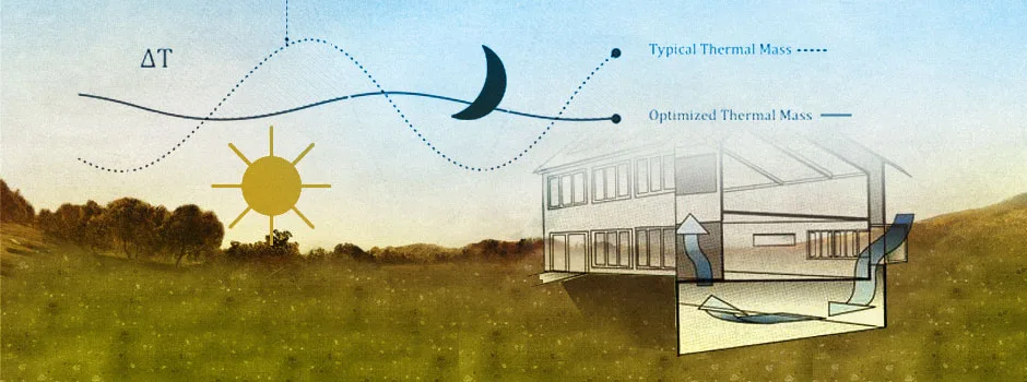
Thermal Lag – Calculating Heat Loss Into the Ground
This page is about understanding thermal lag and thermal mass. These are helpful to understand for any in-ground constructions and, in our case, this includes the Duplicable City Center basement, Earthbag Village (Pod 1) living structures, Tropical Atrium, and Aquapini and Walipinis structures.
In accordance with our open source philosophy and desire to help others interested in sustainable building too, we share here the results of our research into this topic with the following sections:
- What are Thermal Mass and Thermal Lag
- Why are Thermal Mass and Lag Important
- Ways to Contribute
- Consultants
- Thermal Mass and Thermal Lag Details
- Resources & References
- Summary
- FAQ
RELATED PAGES (click icons for complete pages)
")
![]()


")
")


![]()
WHAT ARE THERMAL MASS & THERMAL LAG
 Thermal mass is a material’s resistance to change in temperature and the ability to absorb and store heat energy. Thermal lag is the name given to the delay in the stored heat being released from the material as the ambient temperature decreases. So thermal mass is a material that stores energy and how long that energy is able to be stored as surrounding temperatures change is called thermal lag.
For a material to provide appropriate levels of thermal mass, a combination of three basic properties is required:
- A high specific heat capacity – so the heat energy/kg is maximized
- A high density – the denser the material, the more heat it can store
- Moderate thermal conductivity ” so the rate that heat flows in and out of the material is roughly in sync with the daily heating and cooling cycle of the building
Thermal lag will then depend on the effectiveness of the thermal mass and how extreme the ambient temperature variations are. The better the thermal mass is at holding heat from the hotter parts of the day, and the less extreme the ambient temperature fluctuations are, the slower the thermal lag and the easier it is to regulate temperatures within structures by understanding and using both thermal mass and thermal lag.
WHY ARE THERMAL MASS AND
THERMAL LAG IMPORTANT
Thermal mass and thermal lag are particularly useful where there is a big difference between day and night outdoor temperatures. Thermal mass can be used to store heat when it is warm so that that energy can then be released/used when temperatures drop. Understanding how this works and how it relates to thermal lag is especially helpful in the case of in-ground structures and/or construction of Climate Batteries. In our case, the Duplicable City Center basement, Earthbag Village (Pod 1) living structures, Tropical Atrium, and Aquapini and Walipinis structures are all designed for in-ground construction. They also all include climate batteries, so we’ve invested a significant amount of time researching and understanding both thermal mass and thermal lag. We share here all we have learned in accordance with our open source philosophy and desire to help others interested in applying what we’ve learned too.
WAYS TO CONTRIBUTE TO EVOLVING THIS SUSTAINABILITY COMPONENT WITH US
SUGGESTIONS | CONSULTING | MEMBERSHIP | OTHER OPTIONS
CONSULTANTS ON THERMAL LAG
Vamsi Pulugurtha: Mechanical Engineer
CLICK THESE ICONS TO JOIN US THROUGH SOCIAL MEDIA
![]()
![]()
![]()
![]()
![]()
![]()
![]()
![]()
![]()
![]()
THERMAL MASS & THERMAL LAG DETAILS
Thermal mass and thermal lag details are discussed in this section. Keep in mind the following when considering thermal mass and thermal lag:
- Appropriate use of thermal mass will not only provide comfort but also help in reducing heating and cooling bills.
- Thermal mass is not a substitute for insulation. A high thermal mass material is not generally a good thermal insulator.
- The basic function of thermal mass is to store and release heat energy. The three most important factors are emissivity, heat capacity, and thermal conductivity.
- In general terms, thermal mass and thermal lag are most useful when the outside temperature is both above and below the desired indoor temperature during a normal 24-hour cycle. If the outside temperature stays warmer or stays colder than the indoor temperature, insulation would be most ideal to focus on. This is because the basic function of an insulation material is to obstruct or delay heat transfer which can happen via any combination of the three basic modes of heat transfer: conduction, convection, and radiation. A properly insulated building stops heat flowing into or out of the building.
Now let’s dig deeper into thermal mass and thermal lag with the following sections:
- Understanding Heat Conductivity of Materials
- Understanding Heat Conductivity of Soils
- Understanding Temperatures Around the Year
- Building Above Ground Versus Underground Case Study
- Conclusions
UNDERSTANDING HEAT CONDUCTIVITY OF MATERIALS
 As previously stated, thermal mass is most appropriate in climates with a large diurnal (day-to-night) temperature range. For our specific location, high thermal mass construction with high insulation is desirable since the diurnal range/fluctuation is over 50º F (10° C). Using the Duplicable City Center as an example, we have an underground/earth covered basement which protects the basement from solar radiation and provides additional thermal mass through earth coupling to stabilize internal air temperatures, so ideal combination of thermal mass and insulation can be used to provide required thermal comfort very economically.
The thermal properties of concrete, EPS insulation, and other materials were researched and are provided in the table below.

Time lags for individual materials for specific thickness are listed in the table below.

With the above tables in mind, here are two critical factors in determining the heat storage capabilities of any material:
- The time it takes for a heat wave to propagate from an outer surface to the inner surface, named as time lag.
- The decreasing ratio of its amplitude, called decrement factor. Said differently, decrement factor is the ratio of the indoor temperature’s amplitude to the outdoor temperature’s amplitude.
Depending on the required combinations of materials and thicknesses, the time lag can be directly calculated from the table above. You can do this by multiplying your material in inches by related time lag:
Material(s) (inches) x Related Time Lag (hours) per Inch = Total Time Lag
Example: So if you have 8 inch EPS insulation and 4 inch concrete, using the above table we can calculate the time lag for each and add them together for our total.
- 8 inches EPS will be 528 mins (which is 8 inches * associated time lag per inch of 66min (1.1 hrs = 66 min))
- 4 inch concrete it will be 96 min (which is 4 inches * associated time lag per inch of 24 (0.4 hrs = 24 min))
- 528+96 = 624 minutes (10.4 hours)
Based on the finite element analysis (FEA) we did for the Duplicable City Center boiler room (details below), the average desired temperature of the boiler room was estimated to be 85° F. With this as our ideal room temperature, the large diurnal temperature fluctuations outside (20º F to 90º F average), and our plan to build below ground and have adjacent basement dry-food storage in a target room temperature of 70º F, 10 inches of EPS insulation will give a time lag of 11 hours (10 x 1.1 hours time lag per inch) with 8 inches of concrete giving an additional time lag of 3.2 hours (8 x .4 hours (24 mins) time lag per inch). So the total time lag would be 14.2 hours.
UNDERSTANDING HEAT CONDUCTIVITY OF SOILS
Air temperatures vary over 24-hour cycles. Soil temperatures go through similar cycles, but at greater depths the changes in ground temperature lag farther and farther behind air temperature and eventually the amount of temperature change is much less. With this in mind, the mean annual surface temperature of any location depends on three important factors:
- The exact depth at which you are measuring the temperature.
- The proximity of geothermal heat sources.
- The proximity of ground water.
When we are talking about annual soil temperatures, the most important factor of these three is the depth. At about five feet down, ground temperatures lag three months behind seasonal air temperatures. The lag keeps increasing as you keep going deeper and it reaches six months at 15 feet. Going even further, 30 feet below the soil temperatures are constant, and are more or less equal to the average annual air temperature of that location throughout the year. Further down, at more than 150 feet or more, there is a steady increase of 2.6° C per 320 feet (100 meters).
Soil types also play an important role because different types of soil have different amounts of water and therefore different thermal conductivity levels. Thermal conductivity is measured in Watts per meter-Kelvin (W/m K). So keep the thermal conductivity of soil in mind also when building underground and/or constructing Climate Batteries. Here is a chart to help with understanding the thermal conductivity differences of various soil types.

UNDERSTANDING TEMPERATURES AROUND THE YEAR
Now let’s explore year-round temperatures and how they relate to materials. We stated before that time lag (hours) is the time delay of reaching the peak maximum outdoor temperature to peak maximum indoor temperature. We also shared that decrement factor is the ratio of indoor temperatures amplitude to outdoor temperatures amplitude.
If we take a look at the temperatures around the year for our location in the southwest, the daily temperatures can fluctuate from 20º F to 90º F with seasonal highs as much as 105° F and lows of -10° F. This wide range of temperatures warrant a thermal mass integrated with sound design techniques, which means having appropriate areas of glazing facing appropriate directions with appropriate levels of shading, ventilation, insulation, and thermal mass.
Putting all of this together, you get the graph below that shows the relationship between outdoor temperature variations and their impact on indoor temperatures of structures built with just timber, timber with added external insulation, and timber with added external insulation and partially covered in earth.

BUILDING ABOVE GROUND VS UNDERGROUND CASE STUDY
Combining all of the information above and continuing with our example of the Duplicable City Center basement, let’s explore the difference between building above ground versus underground. This case study is made even more interesting and challenging by adding in the specifics for the boiler room that will also be included in the basement. This boiler room will constantly produce heat (2,390 BTU/hr) and we want to maintain it between 80º and 90º F to maximize the efficiency of the boilers. The adjacent basement is for food storage and has a desired average temperature of
First we need to understand the materials of the basement itself:

City Center Basement Details – Click to enlarge
Assumption made for the boiler room are as follows:
- Based on the previous analysis done on the boiler room, average temperature of the boiler room floor was found out to be 95° to 100° F.
- In the current study the boiler room floor is assumed to be at 95° F to monitor the heat loss into the ground.
- Three different materials are considered below the floor.

Boiler Room Assumptions – Click to enlarge
Here are the Boiler Room finite element analysis (FEA) results based on this information:

Boiler Room FEA Results – Click to enlarge
- Changes in temperature are clear as we go deeper into the ground.
- The rate at which temperature drops depends directly on the temperature of the surrounding soil, which in turn depends on depth and the corresponding air temperature above the ground.
Here are the Boiler Room Floor FEA results:

Boiler Room Floor FEA Results – Click to enlarge
- When we look at the temperature contours on the floor going into the ground, the temperatures drop by about 2º F (from 95º F) by the time they reach the XPS insulation layer.
- From XPS insulation layer just before reaching the aggregate base, the temperatures drop about 20º F.
- By the time we reach the aggregate base, the temperatures drop by 40º F.
Now that we understand the boiler room, let’s add in the rest of the basement with a target average basement temperature of 70º F:

Basement Plus Boiler Room – Click to enlarge
We analyzed both the basement and attached boiler using an extreme ground temperature of 35º F and our actual anticipated average ground temperature of 50º F. This was done to explore the difference that different average ground temperatures make on these two rooms:

Basement and Boiler Temperature Comparison with 35ºF and 50ºF Surrounding Soils – Click to enlarge
Here are just the basement temperatures with an extreme ground temperature of 35º F and our actual anticipated average ground temperature of 50º F. Notice the heat coming from the boiler room on the right also.

Average Basement Temperature Comparison with 35ºF and 50ºF Surrounding Soils
HEAT PENETRATION INTO THE SOIL
Next we ran simulations to show the difference in heat penetration through the soil itself. So above you see the heat within the room, next we wanted to see how a heated room would transfer heat into different types of soils at different temperatures. To do this we assumed a consistent conditioned basement temperature of 70º F and boiler room temperature of 95º F. Ground temperatures were assumed at 35º F or 50º F.

Basement with Boiler Starting Conditions – Click to enlarge
We then chose three different thermal conductivity selections to represent the different soil types:
- 0.22 W/m to represent dry sandy soils
- 2.5 W/m to represent dense and hard soils
- 3.5 W/m to represent wet sandy soils
Here are the results demonstrated for 32 feet below the structure and with starting surrounding soil temperatures of both 35º F (on the left) and 50º F (on the right).

Heat Transfer Through Different Soil Types at Different Temperatures – Click to enlarge
- What this shows is the difference in heat dissipation for different types of soil with different thermal properties. For the soil types in the lower thermal conductivity range (0.22 W/m), we can observe heat being retained more in the soil. For the soil types in the higher thermal conductivity range (3.5 W/m), we can observe the heat dissipating much more compared to the lower thermal conductivity soil.
- More conductivity = more heat transfer. So in both of the pictures the temperatures at the bottom most layer of the soil (at 32 feet) were assumed to be 35º F and 50º F. Heat is coming down from the boiler room and dissipating into the colder soil below the building. So for the very top pictures with lower conductivity, the heat coming down from the building is held within the soil more effectively than the bottom-most pictures with higher conductivities that transfer and lose that heat faster into the surrounding soils.
Note: The pictures above are showing a steady state, meaning the boundary conditions (basement temperature, surrounding soil temperature) have been kept constant and have run long enough to reach a time where the temperature distribution in the soil and basement walls no longer changes appreciably. If the pictures were to show a variable state, the faster heat dissipation would be visible (and shown as larger) in the higher conductivity soils.
BUILDING ABOVE VERSUS IN-GROUND
Next we ran a finite element analysis (FEA) for this basement when building above ground versus underground.
- The image and details on the left show the temperature distribution when the building is above the ground.
- The image and details on the right show the same when building under the ground.
- Analysis is of a hot day with external atmospheric temperature being 95° F.
- Soil type chosen was somewhere between medium and course sand, so 3.5 W/m of conductivity.
- Analysis was done without insulation added to the walls.

City Center Basement FEA Comparing Above-ground and Below-ground Construction – Click to Enlarge
In this example comparing the same room with concrete walls and no additional insulation, a difference of 15° F was observed when comparing above-ground construction to in-ground construction. So, depending on the required temperature the area needs to be maintained at, in-ground construction provided significant benefits but additional approaches should be considered for maintaining our desired cooler internal temperatures. These include insulating the external walls, the boiler room walls, and any other heat sources that may exist.
BUILDING ABOVE VERSUS IN-GROUND WITH INSULATION
Here’s what the results looked like once we added insulation and ran the simulations again to compare above-ground and below-ground:

Above vs Below-ground Construction Analysis with the Addition of Insulation – Click to enlarge
- In the top half of the above image, building below-ground with insulation versus without produced a 12º F average temperature difference in the room.
- In the bottom half of the above image, insulation versus no insulation in above-ground structures showed a 13º F reduction in temperature when measured 3.5 meters from the same 95º F wall with 10 inches of added EPS insulation.
Here is a chart adding to our data the results of in-ground structures versus above-ground structures with various outdoor temperatures:

In-ground Structures vs Above-ground Structures with Various Outdoor Temperatures – Click to enlarge
CONCLUSIONS
We can clearly observe the difference in temperature dissipation for different types of soil with different thermal properties. For the soil types in the lower thermal conductivity range (0.22 W/m), we can observe a higher level of heat retention as the heat transfers from the building into the soil. For the soil types in the higher thermal conductivity range (3.5 W/m), we can observe a lower level of heat retention as heat transfer/dissipation/loss is much higher compared to the lower thermal conductivity soil. (Reference Graphic)
Depending on the soil type and external temperatures, we can get a very good understanding of how much heat is being dissipated into the ground from this data.
Under the ground constructions/coupling with the earth provides the occupants with resultant indoor temperatures which are far more stable. (Reference Graphic)
Here’s a graphic demonstrating structures from least-to-most utilization of thermal mass to stabilize their temperatures. Our FEA process confirmed this for our structure too.

Least-to-Most Examples of Buildings Utilizing Thermal Mass for Temperature Stabilization – Click to enlarge
RESOURCES & REFERENCES
Related resources can be found below:
References:
- Ahmed, T. (2012). Investigating The Impact Of Thermal Mass. Ryerson University.
- Asan, H. (2005). Numerical computation of time lags and decrement factors for different building
materials. Department of Mechanical Engineering, Karadeniz Technical University, 61080
Trabzon, Turkey. - H. Asan, Y. S. (1997). Effects of Wall’s thermophysical properties on time lag and decrement
factor. Department of Mechanical Engineeting, Karadeniz Technical University, 61080 Trabzon,
Turkey. - Hadi Ramin, P. H. (2015). Determination of optimum insulation thickness in different wall
orientations and location in Iran. Advances in Building Energy Research. - Mitalas, G. (1982). Basement Heat Loss Studies. DBR Paper No. 1045 of the Division of
Building Research. - Shea, S. M. (2013). Performance Evaluation of Modern Building Thermal Envelope Designs in
the Semi-Arid Continental Climate of Tehran. http://www.mdpi.com/journal/buildings/. - Srivastava, B. S. (2008). Influence of thermal insulation on conductive heat transfer through roof
ceiling construction. Central Building Research Institute (CBRI).
Websites:
- Article: Passive Home Design Using Thermal Mass
- Article: Thermal Lag Heating
- Article: What’s the Difference Between Insulation & Thermal Mass?
- Article: Thermal Mass vs Insulation: Materials Choice
- Article: Cob, Straw Bale or Earthbag: Which Is the Best?
- Article: Autodesk.com – Thermal Properties of Materials
- Article: British Geological Survey (BGS.ac.uk) – Ground source heat pumps
- Article: Ground Temperatures as a Function of Location, Season, and Depth
SUMMARY
Having a temperature analysis of the surrounding air/soil inside and around the structures we are designing gives us a very clear picture of what is going on. With thermal mass and thermal lag info in hand, accurate and sound decisions can be made to create sustainable structures and designs. Using thermal mass to our advantage means our buildings will have a much higher average temperature in the winter, and a lower average temperature in the summer, which greatly reduces our heating and cooling costs throughout the year.
FREQUENTLY ANSWERED QUESTIONS
Q: What is the difference between thermal lag and thermal mass?
Thermal mass is a material’s resistance to change in temperature and the ability to absorb and store heat energy. Thermal lag is the name given to the delay in the stored heat being released from the material as the ambient temperature decreases.
Q: What is the context of the basement and the boiler room within the larger One Community project?
The basement and boiler are part of the open source Duplicable City Center designs. Visit the Duplicable City Center open source hub to learn complete details.
![]()