One Community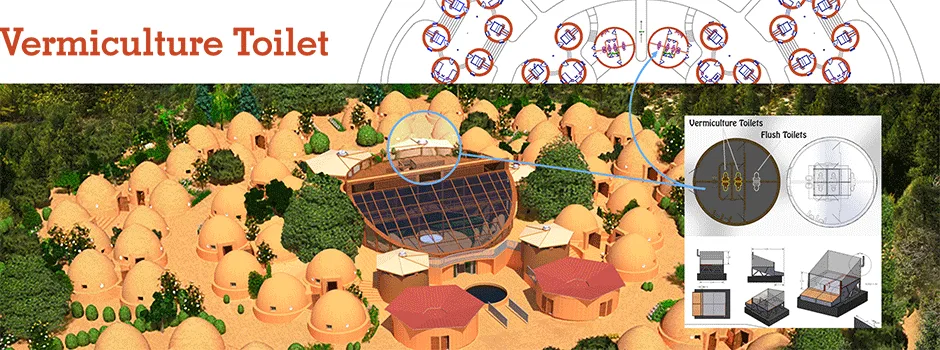
Vermiculture Eco-toilet Design
As part of the open source Earthbag Village (Pod 1), we will be building and are open source project-launch blueprinting an ultra-eco vermiculture (worm composting) solid waste processing option. For county compliance, these Vermiculture Toilets also include a traditional toilet and septic option. This page discusses these designs with the following sections:
- What is a Vermiculture Eco-toilet
- Why Open Source a Vermiculture Eco-toilet
- Consultants for this Component
- Vermiculture Eco-toilet Design Details
- DIY Eco-toilet Seat
- Vermiculture Chamber Engineering Details
- FEA / Analytical Calculations for Unistrut Structure
- Slider Design & Calculations
- Vermiculture Storage Chamber Load and Handle Stress Evaluation
- Chamber Load and Handle Force FEA Analysis and Results
- Ventilation System Design for Vermicomposting Eco-Toilet Space
- Vermiculture Eco-toilet Replication Details
- Operation and Maintenance
- Vermiculture Operating Conditions & Schedule
- Vermiculture System Temperature Control
- Temperature Monitoring Devices
- Temperature Control Devices
- Ventilation System Design for Vermicomposting Eco-Toilet Space
- Cooling/Ventilation Devices for Vermiculture Compost
- Sensor Selection for Chamber Gas Regulation
- Vermiculture Container Transport Solution
- Resources
- Summary
- FAQ
NOTE: THIS PAGE IS NOT CONSIDERED BY US TO BE A COMPLETE AND USABLE TUTORIAL UNTIL
WE FINISH OUR OWN CONSTRUCTION OF THIS COMPONENT, CONFIRM ALL THE DETAILS, AND ADD
TO THIS PAGE ALL THE RELATED VIDEOS, EXPERIENCE, AND OTHER UPDATES FROM THAT BUILD.
IN THE MEANTIME, YOU CAN HELP US COMPLETE IT ALL SOONER WITH THE FOLLOWING OPTIONS:
INPUT & FEEDBACK | JOIN OUR TEAM | HELP US BUY THE PROPERTY
RELATED PAGES (click icons for complete pages)







CLICK THESE ICONS TO JOIN US THROUGH SOCIAL MEDIA


WHAT IS A VERMICULTURE ECO-TOILET
 “Vermiculture” is the process of using worms to decompose organic food waste or feces. With this process, the waste/feces is turned into a nutrient-rich residue called vermicompost. Vermicompost residue is an excellent fertilizer because it adds organisms that are beneficial to soil and plants because they further help break down organic materials and convert nutrients into a more available food form for plants. Vermiculture also improves soil aeration and increases its water-holding capacity. All of this leads to plants that grow stronger, bigger, and are more drought tolerant and disease resistance than those grown using less natural methods.
Built twice in the North half of the village, the vermiculture toilet designs we have created contain six toilets, two of which are traditional septic toilets and four that are vermiculture solid-waste processors. They are designed with the following goals/criteria:
- Demonstrate indoor worm composting as an option for repurposing human waste
- Include a traditional septic for people that want one and counties that need one
- Demonstrate the Earthbag Village as a duplicable village model capable of producing zero waste
- Make it all DIY replicable, cost effective, dependable, and easy to maintain
The picture below shows the Vermiculture Toilet Version One designs. These have been updated but their location in relation to the flush toilets, and the central location of these structures within the Earthbag Village and just north of the Tropical Atrium, is the same:

The One Community Earthbag Village Vermiculture Toilets | Concept Render ” View Looking Southwest
This picture shows the updated vermiculture designs:
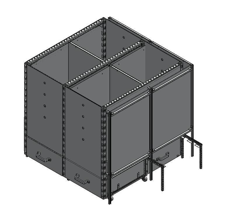
Updated Final Vermiculture Design – Click to Enlarge
WHY OPEN SOURCE A VERMICULTURE ECO-TOILET
Vermicomposting is a simple, effective, natural and sustainable method of processing food waste and feces. When food is sent down a garbage disposal, or when it is buried in a landfill, nature’s natural and beneficial recycling process is being bypassed. The traditional septic and municipal waste processing for handling feces also requires significant resources and wastes what could be a nutrient-rich (and more beneficial) alternative to synthetic fertilizers. Vermiculture is better for plants, better for the environment, and saves money and resources.
Open source project-launch blueprinting a solution like this supports our goals for positive and permanent global transformation and creating sustainable and self-replicating teacher/demonstration hubs. It is also directly in alignment with our Purpose and Mission, our Global-transformation Pledge, and Highest Good philosophy for open source creation, sharing, and making a difference in the world.
Here is the Work Breakdown for completion of the Vermiculture Toilet designs:

Vermiculture Bathroom | Work Breakdown Structure of Steps for Tutorial Completion – Click to Enlarge
WAYS TO CONTRIBUTE TO EVOLVING THIS SUSTAINABILITY COMPONENT WITH US
SUGGESTIONS | CONSULTING | MEMBERSHIP | OTHER OPTIONS
KEY CONSULTANTS TO THE EARTHBAG VILLAGE VERMICULTURE TOILET DESIGNS
Adil Zulfiquar: Engineer
Adolpho Maia: Mechanical Engineering Student
Ajay Adithiya Kumar Elancheliyan Tamilalagi: Mechanical Engineer
Anil Karathra: Mechanical Engineer
Betty Lenora: Earthbuilding Instructor and Author
Christian Ojeda: Mechatronic Engineer
Dijimba “Joss” Kabuyi Ilunga: Electrical Engineer
Douglas Simms Stenhouse: Architect and Water Color Artist
Erika Yumi Tamashiro: Architecture and Urban Design Student
Fernando Remolina: Industrial Engineer specializing in Project Management
Jorge Antonio Ricardo: Mechanical Engineering Student
Joseph Osayande: Mechanical Engineer
Karthik Pillai: Mechanical Engineer
Lin Xu: Mechanical Engineer
Malhar Y. Solanki: Mechanical Engineer
Manjiri Patil: Mechanical Design Engineer
Matheus Manfredini: Civil Engineering Student specializing in Urban Design
Rahul Kulkarni: Mechanical Engineer
Rishikhesh Chakrapani: Mechanical Engineer
Rizwan Syed: Mechanical Engineer
Victor Herber: Mechanical Engineer
Yagyansh Maheshwari: Mechanical Engineer
VERMICULTURE ECO-TOILET DESIGN DETAILS
The basic idea of the Vermiculture Toilet is shown below with a receiving structure large enough, and filled with enough worms, to process all the solid human waste (feces) from 40 people. Worms process/eat their way from the bottom to the top as they follow the food source and leave behind vermicompost. The main chamber is sloped towards the front so the vermicompost slides into removable chambers that can be moved and emptied using an electric pallet jack. Urine separating toilet seats and holes in the bottom of the sloped bottom of the receiving chamber remove liquids. Smells are addressed with venting, fans, and mixing in additional slow-release carbon-rich materials (such as wood chips and shavings) with more bioavailable carbon stores like leaves, grasses, etc. We’ll then use regular soil testing to determine if the resulting vermicompost is safe only for trees and non-food plants or also for food crops as other researchers (see the resources section) have shown is possible.
We discuss these details and more with the following sections:
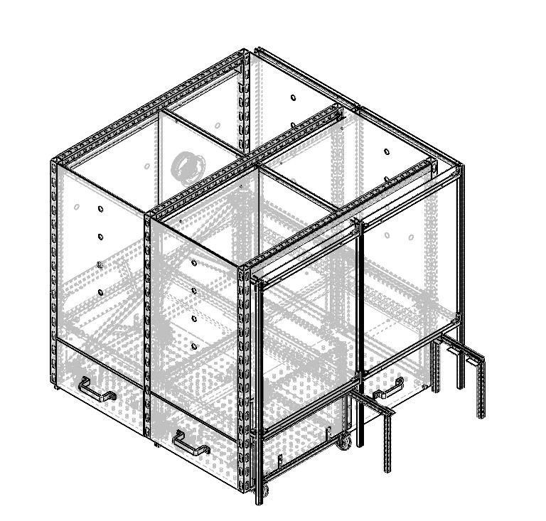
Vermiculture Updated Design (2.0)
DESIGN REQUIREMENTS
The Earthbag Village consists of 72 earthbag hotel-room-styled cabanas measuring 150-200 ft² (14-18.6 m²), plus 4 Communal Eco-shower domes, 2 Net-zero Water-Recycling Bathroom, 2 toilet domes with the vermiculture toilets described on this page, and the central Tropical Atrium. Total village capacity is 160 people.
If the vermiculture toilets are used exclusively, there will be 80 people using them. Based on our research, the average person produces approximately 0.556 lb (0.25 kg) of waste daily. So we will have a daily production of:
80 (people) * 0.55 lb (0.25 kg) * 1.1 (safety factor) = 48.5 lb (22 kg) per day
The goal is to process and use this waste in our agriculture system as fertilizer in order to achieve sustainability. There will be 4 vermiculture toilets, shown in yellow, contributing to this. There will also be two flush toilets, they are shown below in gray. In the future, flush toilets are to be eliminated in order to optimize the vermicomposting area, thereby utilizing vermiculture toilets exclusively. The vermiculture system is to be located directly underneath the toilets.

WORM REQUIREMENTS
There are different species of commercially available worms that can be used in the vermiculture process. Here is a list. Red Wigglers are commonly regarded as the most effective worms at processing waste. They have set the standard for composters. They are more voracious than other compost worms and their ability to survive in captivity is unparalleled.
The optimal temperature for Red Wigglers to live in has been the subject of research, and the results or that study are as follows:

Originally, there were some temperature concerns. The proposed structure though, will be built into the ground. This should make it fairly easy to keep the worm area between 55-70°F (13-21°C) as long as the doors are insulated properly. The Red Wigglers were also chosen for their ability to survive in varying temperatures, although they do slow down in the cold.
The recommended worm density can be a difficult parameter to set. One online source recommends using 0.25 lb – 0.5 lb of worms per ft². If applied to this system, assuming a density of 0.5 lb/ft² and a surface area of 60 ft², there would be 30 lbs of worms to service this system.
Worms eat about half of their weight each day. This means about 15 lbs of waste per day. If the process is to be completed in the top 4 feet of the system, a conservative estimate, the number of worms could be quadrupled, increasing the amount to 60 lb of processed waste per day. This would easily cover our maximum input calculated above as 48.5 lb (22 kg) per day.
DIY TOILET ASSEMBLY INSTRUCTIONS
This guide walks you through assembling the vermicomposting toilet unit shown in the provided design renderings. Ensure you refer to the associated Design Report for the detailed cut-list, material specifications, and dimensioned stencils before beginning construction. All wooden parts should be pre-cut as per the cut-list to ensure a smooth build process.
We cover the construction and assembly with the following sections:
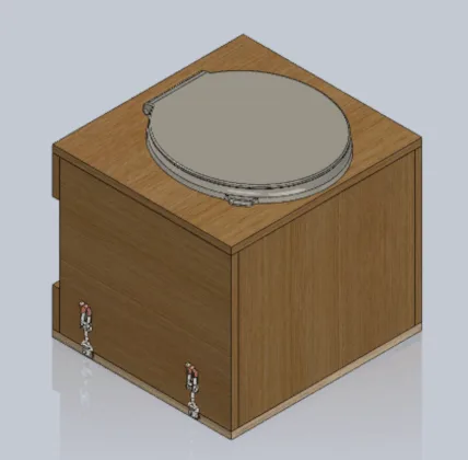
CAD Model of the Fully Assembled DIY Toilet Seat
PROTECTING YOUR WOOD
To protect the toilet structure from moisture damage, apply Olympic Waterguard 1 gal. Clear Wood Sealer (Home Depot SKU: 55260XI-01). This sealer is transparent, water-based, and ideal for outdoor wood protection.
Application Tips:
- Apply with a brush, roller, or sprayer on dry wood.
- Use 1–2 coats for best protection.
- Let it cure completely (typically 24–48 hours) before assembling the unit.
- Optionally, a final coat may be added on the inner surfaces post-assembly.
ASSEMBLY INSTRUCTIONS
Below are the detailed step-by-step assembly instructions for constructing the unit. These instructions assume basic familiarity with hand tools and follow a logical sequence to ensure ease of construction and accuracy:
- Start with the Front Wall Panel
- Add Corner Brackets
- Attach Side Panels
- Fix the Back Wall
- Attach the Seat Top
- Mount Latches to Side Walls
- Add Toilet Seat and Lid
- Prepare the Latch Base
- Attach Hook Plates to Latch Base
- Place Toilet on Base & Latch it in
- Install the Urine Diverter
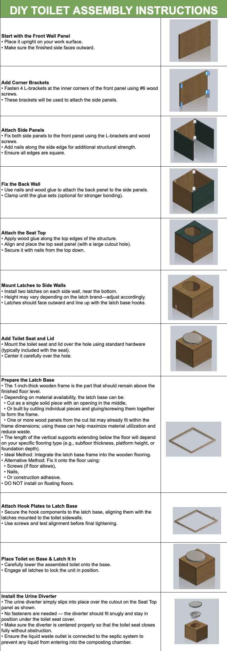
Click for source table
FINAL CHECKS
- Confirm all panels are secure and aligned.
- Check latch engagement is tight but operable.
- Confirm seat fit and lid operation.
- Apply a final internal protective waterproofing coat if needed.
DIY ECO-TOILET SEAT
This design supports the creation of four modular toilet seat bases for eco-friendly sanitation systems such as vermiculture and dry composting toilets. Each unit is designed for simplicity, durability, and ease of local fabrication using standard plywood and commonly available hardware.
The unit securely supports a toilet seat above a waste receptacle and features a flat-packed, bracket-based construction with a removable interface for flexibility in community-scale or mobile applications. Full-scale A1 stencil drawings are included to enable accurate and straightforward fabrication using direct templates during cutting.
This report includes:
- Proper (and Assumed) Use of Components
- Material Specification
- Design Description
- Design Considerations
- Sustainability Considerations
- Documentation
PROPER (AND ASSUMED) USE OF COMPONENT
 Before you begin assembling the vermicomposting toilet, please review and follow these safety guidelines to prevent injury and ensure a smooth build process. Below is a video demonstrating proper assembly posture and safe handling techniques — including lifting, fastening, and general tool use — to protect your back, hands, and feet while ensuring the structure’s durability.
- Always wear eye protection, gloves, and closed-toe shoes when cutting, drilling, or handling hardware.
- Use clamps or a second set of hands to hold parts steady during assembly.
- Do not stand or sit on the unit until all panels are securely fastened and the structure is latched to the floor.
- Apply sealer or adhesive in a well-ventilated area and allow full drying time as instructed.
- Avoid over-tightening screws, especially into softwood, to prevent cracks or splits.


VIDEO COMING: HOW TO PROPERLY HAMMER IN THE SLIDER FOR MAXIMUM SAFETY AND LONGEVITY
SEE OUR HOW TO HELP AND/OR CROWDFUNDING CAMPAIGN PAGE TO HELP CREATE ALL THE TUTORIAL VIDEOS FASTER
MATERIAL SPECIFICATION
The materials chosen for this design prioritize accessibility, durability, and simplicity. Standard plywood and steel angle brackets form the core structure, enabling easy construction with basic tools. The components are dimensioned for efficient material usage and designed for straightforward assembly, making them ideal for low-resource environments or DIY builders.
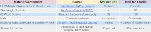
DIY Toilet Seat Material Specification Table – Click for Source table
DESIGN DESCRIPTION
Each toilet seat base consists of six plywood panels: side walls, a front wall, two rear cross-members, and a seat top with a toilet cutout. A seventh component, the latch base, is fixed directly to the wood floor, providing a stable foundation for securely mounting the vertical structure using industrial latches. This design allows the main toilet seat enclosure to be easily installed or removed, supporting modular maintenance and relocation.
The top panel is designed to be compatible with standard toilet seats and distributes weight evenly across the structure. All components are optimized to minimize material waste and ensure consistent fabrication.
Full-size A1 stencil drawings are provided for each panel to enable precise cutting without the need for digital fabrication tools.
DESIGN CONSIDERATIONS
This design emphasizes practicality, strength, and adaptability. By incorporating a reinforced plywood frame and modular features, it supports long-term use in demanding environments while remaining easy to assemble, repair, and upgrade. The approach ensures maximum usability with minimal tools and effort, empowering local builders to maintain and adapt the units as needed.
- Structural Integrity: The plywood panels form a box frame reinforced with steel angle brackets, offering rigidity and load distribution suitable for repeated use in public or off-grid settings.
- Tool Accessibility: The design only requires basic tools (saw, drill, screwdriver), making it accessible to low-resource communities or DIY builders.
- Material Efficiency: Components are dimensioned to maximize yield from standard plywood sheets, requiring only two sheets for four complete units.
- Modularity: The latch-based installation system allows units to be detached or swapped without damaging surrounding infrastructure.
- Repair and Upgrades: Screw and bracket connections allow easy disassembly for repair or adaptation, extending product life.
SUSTAINABILITY CONSIDERATIONS
Sustainability is central to this design, from efficient use of materials to ease of reuse and recycling. The structure avoids excessive plastic, relies on locally available components, and supports disassembly without damage. These choices reduce environmental impact and promote circular use, aligning with long-term ecological goals.
- Material Efficiency: Each unit requires only half a sheet of plywood, allowing four units to be constructed from two full sheets with minimal waste.
- Reusability: Components are fastened mechanically, not glued, making them easy to replace or disassemble for transport or end-of-life recycling.
- Minimized Plastic Use: The design avoids plastic components, except for optional toilet seat fittings.
- Local Sourcing: All parts are readily available from standard building supply or online sources.
DOCUMENTATION
The following full-size technical drawings are attached to this report and intended for printing on A1 sheets:
- Seat Top PDF | SolidWorks
- Side Wall PDF | SolidWorks
- Front Wall PDF | SolidWorks
- Back Wall PDF | SolidWorks
- Latch Base PDF | SolidWorks
These drawings are to be used as cutting stencils during fabrication to ensure dimensional accuracy and reduce build time.
VERMICULTURE CHAMBER ENGINEERING DETAILS
The vermiculture chamber is positioned below the vermiculture toilets as shown here.
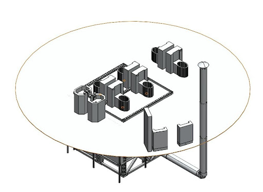
The Unistrut assembly is designed as a modular, multi-compartment structural frame utilizing F2000 series Unistrut (1-5/8″) channel profiles.
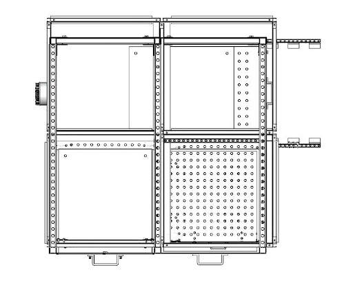
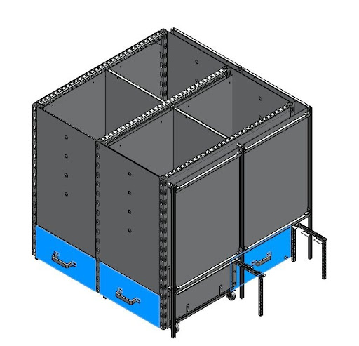
The overall architecture follows a Post-and-Beam configuration, which ensures efficient vertical load transfer, lateral stability, and ease of modular assembly and disassembly.
We discuss this here with the following sections:
OVERALL FRAME GEOMETRY
The structure occupies a total plan footprint of approximately 101.3 inches (length) by 101.3 inches (width), with a total vertical height of 96 inches. The frame is arranged as a symmetric 2×2 grid, forming four distinct compartments of equal size. Each compartment is designed to independently house a standardized vermicompost drawer unit, allowing waste to be collected, processed, and removed from each compartment without disturbing adjacent units.
VERTICAL MEMBERS
Six continuous 96-inch vertical strut columns serve as the primary compression members of the assembly. These columns carry all gravitational and dynamic loads generated by the vermicompost payload and the self-weight of the frame, transferring them directly downward to the base interface.
The image below shows the vertical column layout and positioning across the full frame footprint:
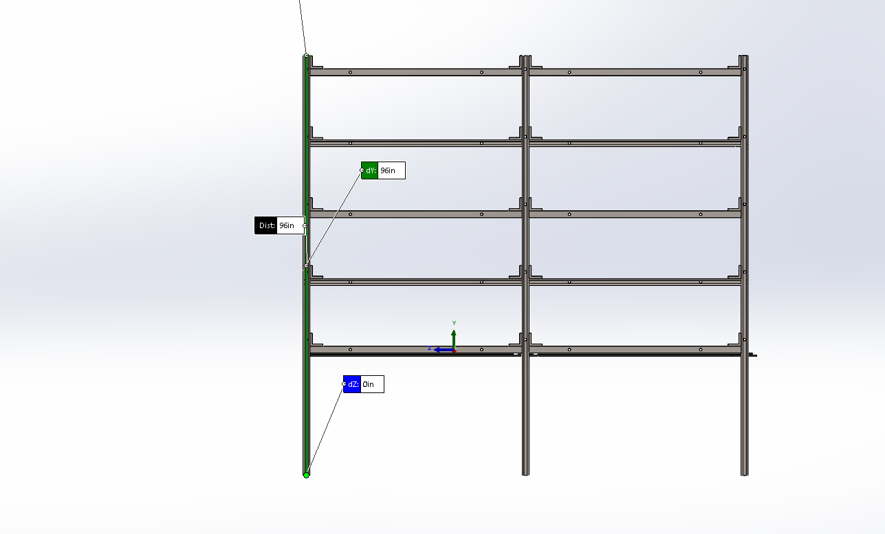
Figure 1: Vertical column layout and positioning across the full frame footprint – Click to Enlarge
The spacing of horizontal tiers is specifically chosen to minimize the unbraced column length, reducing the risk of column buckling under the applied compressive loads. Each tier also acts as a direct load path from the drawer units to the vertical columns.
HORIZONTAL MEMBERS
Five distinct tiered layers of horizontal struts are distributed along the height of the frame. These horizontal members perform two critical structural functions: they provide lateral racking resistance to keep the frame square under load, and they form the shelf-like support system on which the vermicompost drawer units rest.
The image below shows the horizontal tier arrangement and vertical spacing across the full height of the assembly:
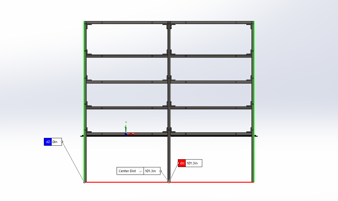
Figure 2: Horizontal tier arrangement and vertical spacing across the full height of the assembly – Click to Enlarge
The spacing of horizontal tiers is specifically chosen to minimize the unbraced column length, reducing the risk of column buckling under the applied compressive loads. Each tier also acts as a direct load path from the drawer units to the vertical columns.
CONNECTION INTERFERENCE
All primary orthogonal joints, where horizontal struts meet vertical columns, are secured using 90-degree L-brackets. These brackets ensure rigid, moment-resistant load transfer between tiers and columns, maintaining the squareness of the 101.3-inch spans. Because Unistrut relies on friction-based clamping through channel nuts, all connection hardware is fully torqued to manufacturer specifications to achieve the bonded behavior assumed in the structural analysis.
The image below shows a typical L-bracket connection at a horizontal-to-vertical joint:
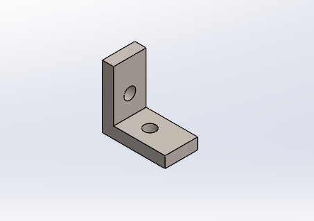
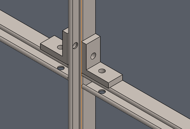
Figure 3: 90-degree L-bracket used at all primary orthogonal joints to provide moment-resistant load transfer between horizontal struts and vertical columns – Click to Enlarge
SUPPORT LOCATIONS
The support scheme for the Unistrut assembly is defined to ensure full structural stability under all anticipated load conditions and to establish accurate boundary conditions for the finite element analysis. The frame relies on three categories of support, each serving a distinct structural role:
- Base Supports: The frame utilizes nine vertical leg attachments. In the simulation, these are modeled as fixed geometry at the floor interface, representing the unit being bolted to a concrete pad using standard Unistrut base plates.
- Intermediate Bracing: Horizontal members are spaced at vertical intervals to minimize the unbraced length of the columns, preventing buckling under compressive load.
- Mechanism Interface Supports: Specific horizontal tiers act as the primary structural anchors for the internal dumping mechanism, distributing the weight of the vermicompost through the strut’s internal channel lips.
STRUCTURAL ANALYSIS METHODOLOGY
The structural integrity of the Unistrut assembly is verified through a dual-verification approach combining classical analytical hand calculations with computational Finite Element Analysis (FEA). This dual approach ensures that the design is validated by both first-principles engineering theory and a detailed numerical simulation of the full three-dimensional assembly, providing a high degree of confidence in the reported results.
ANALYTICAL CALCULATION
Hand calculations are performed using Euler-Bernoulli beam theory to evaluate the two primary serviceability and strength checks for the governing horizontal members: maximum mid-span deflection and maximum bending stress. The deflection of a simply supported beam under a uniformly distributed load is calculated using the standard formula:
The maximum deflection is equal to five times the distributed load per unit length multiplied by the span length raised to the fourth power, divided by three hundred and eighty-four times the elastic modulus multiplied by the second moment of area of the cross-section.
δmax = 5wL4384EI
These analytical results are cross-referenced with Unistrut’s published Maximum Allowable Beam Loads to confirm consistency with manufacturer-validated data.
FINITE ELEMENT ANALYSIS (FEA)
A linear static FEA study is conducted within SolidWorks Simulation to evaluate the full three-dimensional stress state, displacement field, and factor of safety across all components of the assembly simultaneously. The FEA model includes all primary structural members and applies loads and boundary conditions consistent with the worst-case operating scenario.
The mesh strategy uses high-quality parabolic tetrahedral elements throughout the model, with localized mesh refinement applied at bolt-hole interfaces and channel corner regions, where stress gradients are highest and accurate stress capture is most critical. A coarser mesh is used in regions of low stress gradient to maintain computational efficiency without sacrificing accuracy in critical areas.
The analytical hand calculation results and the FEA displacement outputs are compared directly as a cross-check. Agreement within the same order of magnitude between the two methods confirms that the FEA model is correctly set up and that the results are physically meaningful. In this study, both methods converge on a maximum deflection of approximately 1.68 mm, confirming good agreement.
LOAD CASES
To simulate worst-case operating conditions and environmental factors, four load cases are applied to the Unistrut assembly. Each load case targets a specific aspect of the structural response, from static self-weight through to dynamic impact loading during the dumping cycle. The table below summarizes each load case, its description, and the method by which it is applied in the simulation.
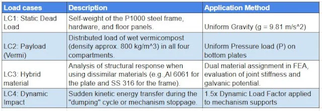
Table 1: Summary of load cases applied to the Unistrut assembly in the structural analysis – Click for source
SUMMARY
The Unistrut assembly designed for the vermiculture toilet facility provides a structurally sound, cost-effective, and easily manufacturable solution for supporting a 2,300 kg vermicompost payload across four independent compartments. The modular F2000 series Stainless Steel 316 frame, arranged in a symmetric Post-and-Beam configuration with six vertical columns and five horizontal bracing tiers, was validated through both analytical hand calculations and SolidWorks FEA. The structural performance of the hybrid Aluminum 6061 / Stainless Steel 316 configuration is further discussed in the following FEA Calculations section.
FEA / ANALYTICAL CALCULATIONS FOR UNISTRUT STRUCTURE
A linear static Finite Element Analysis (FEA) supported by analytical hand calculations was conducted to evaluate the structural performance of the Unistrut support assembly under gravity and maximum waste loading. The study focused on stress, displacement, serviceability, and factor of safety, with analytical calculations used to validate the numerical results and confirm overall structural behavior.
To optimize the structure, I compared Stainless Steel 316 and Aluminum 6061 to balance safety with logistical efficiency. While an all-steel design met the 2,300 kg load requirements, its high self-weight (3,495 lbs) was impractical for shipping and installation. By engineering a hybrid configuration, I achieved a 35% weight reduction (1,251 lbs) while keeping deflection within conservative L/360 serviceability limits.
We discuss this here in the following sections:
- Material Definition
- Results and Discussion
- Stress Analysis
- Deflection Limits
- Factor of Safety
- Conclusion
- Frequently Asked Questions (FAQ)
MATERIAL DEFINITION
The Unistrut assembly was modeled as a multi-material structure to reflect the intended design configuration. Material properties, including elastic modulus, density, Poisson’s ratio, and yield strength, were obtained from the SolidWorks Simulation material database and applied on a component-wise basis. The two materials assigned across the assembly are described below:
- Stainless Steel (SS-316): Assigned to primary load-carrying members and critical connection regions requiring higher strength and durability.
- Aluminum (Al-6061): Assigned to secondary members where weight reduction is desired while maintaining adequate stiffness and serviceability.
Material properties, including elastic modulus, density, Poisson’s ratio, and yield strength, were obtained from the SolidWorks Simulation material database and applied on a component-wise basis.
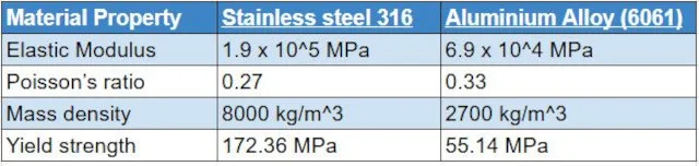
Table 1: SolidWorks Material Properties (Stainless Steel 316 and Aluminium Alloy 6061) – Click for source table
BOUNDARY CONDITIONS
To establish a realistic simulation, I defined specific Boundary Conditions that replicate the physical environment and operational constraints of the Unistrut assembly. These conditions are critical for ensuring that the load paths within the Finite Element Analysis (FEA) model behave as they would in a real-world installation, allowing for an accurate assessment of both structural stability and serviceability.
MODELING APPROACH
The Unistrut assembly was analyzed using a linear static analysis to evaluate its response under gravity and distributed mass loading. All Unistrut components were included in the study and modeled using bonded component interaction through default contact settings to ensure proper load transfer between connected members.
SUPPORT (FIXTURES)
The structure was constrained using fixed geometry at the base supports to represent anchorage to a rigid concrete foundation, restraining all translational and rotational degrees of freedom and simulating fully fixed connections provided by anchor bolts and base plates.
The image below shows the fixed constraint locations applied to the base of the Unistrut support structure in the simulation environment:
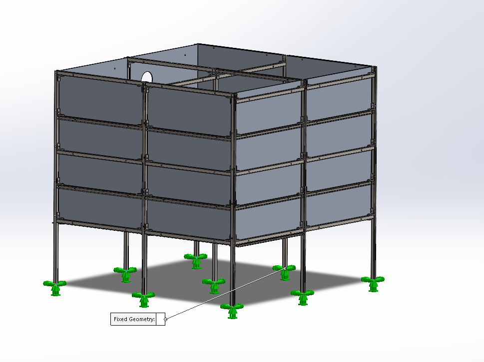
Figure 1: Fixed base constraints simulate rigid anchorage to the concrete foundation – Click to Enlarge
LOADS APPLIED
The structural integrity of the Unistrut assembly was tested against two primary loading conditions to simulate the most demanding operational environment. These two load cases are applied simultaneously in the simulation to represent real-world conditions:
- Gravity loading: Applied in the global negative Y-direction (vertical) to account for the self-weight of all structural members.
- Distributed mass loading: A distributed mass of 2,300 kg was applied to simulate the maximum waste accumulation load over 6 months.
The 2,300 kg distributed mass load was derived from the project’s vermiculture mass calculation sheets, which track the total unprocessed mass accumulation over 6 months. The image below shows both loading conditions as applied in the simulation:
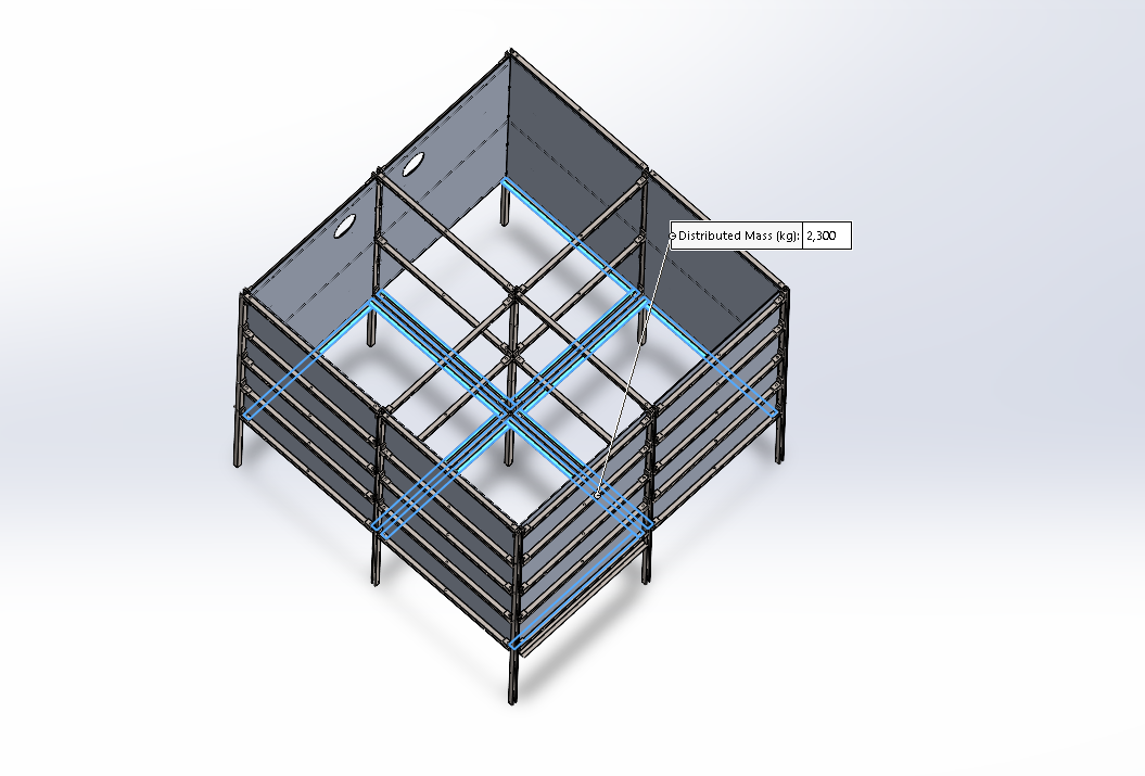
Figure 2: Gravity and Mass Loading on the Unistrut support structure – Click to Enlarge
MASS PROPERTY OF UNISTRUT
The mass properties tool within SolidWorks 2025 was used to calculate the precise gravitational impact of each material configuration. This step was necessary to validate the self-weight assumptions used in the analytical calculations and to quantify the specific weight savings achieved by transitioning to a hybrid model. The following data establishes the structural benchmark by documenting the mass and inertial properties of each design configuration.
ALL-STAINLESS STEEL 316 CONFIGURATION
The image below shows the mass property output for the primary all-Stainless Steel 316 configuration. This serves as the structural benchmark for strength, but also represents the highest self-weight scenario of the two configurations assessed:
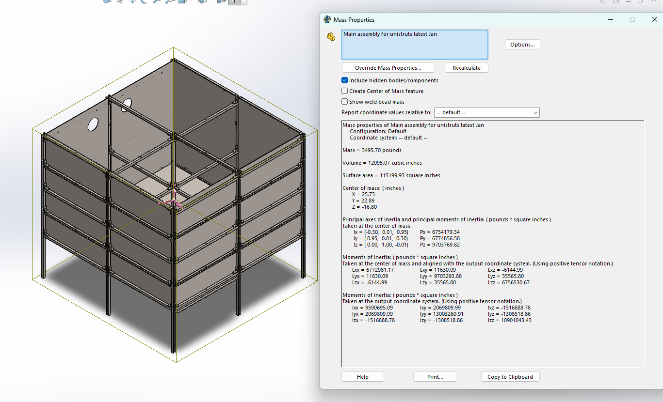
Figure 3: Primary Stainless Steel 316 configuration showing a total assembly weight of 3,495.7 lbs – Click to Enlarge
HYBRID CONFIGURATION
The image below shows the mass property output after implementing Aluminum 6061 secondary components. This configuration achieves a significant reduction in total assembly weight, though at a cost to localized structural performance, as discussed in the sections that follow:
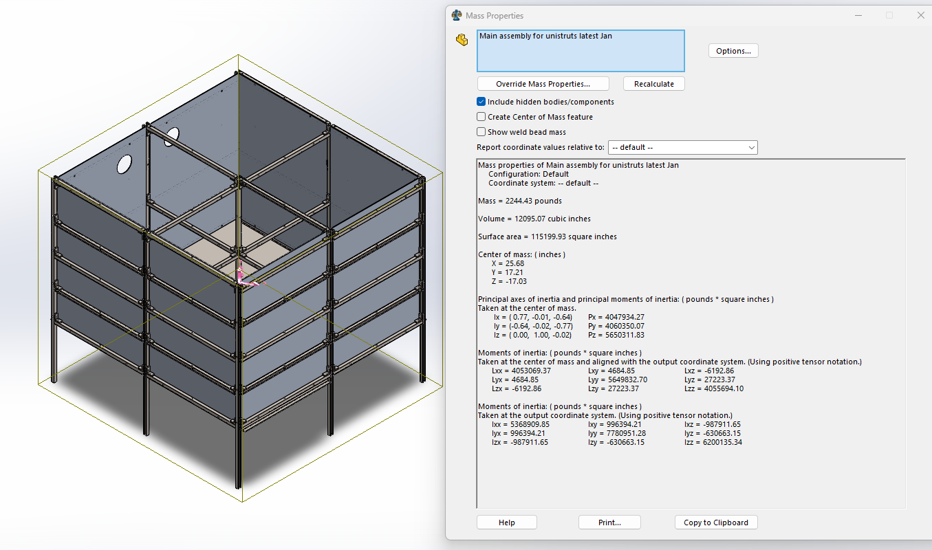
Figure 4: Hybrid configuration showing a total assembly weight of 2,244.4 lbs – Click to Enlarge
Implementing Aluminum 6061 components reduces total assembly weight to 2,244.4 lbs, a 35% reduction. However, the lower material yield strength leads to localized FOS failure under the required 2,300 kg operating load.
ANALYSIS OF MASS PROPERTIES
The weight reduction observed between the two configurations results directly from the density difference between Stainless Steel 316 and Aluminum 6061. Replacing secondary members with aluminum reduces the total self-weight of the assembly as follows:
- Initial configuration (all-SS-316): Total assembly mass = 3,495.70 lbs
- Hybrid configuration (SS-316 & AL-6061): Total assembly mass = 2,244.43 lbs
- Total weight saved: Approximately 1,251 lbs (567 kg), representing a 35% reduction in self-weight
While this weight reduction improves shipping logistics and reduces installation complexity, it introduces structural trade-offs at the material interface that are examined in the following section.
WHY THE FOS FAILED IN HYBRID
Although the hybrid configuration successfully reduces total assembly weight, the Factor of Safety (FOS) was found to fail at localized connection points due to the significant difference in material properties between Stainless Steel 316 and Aluminum 6061. Three key factors contribute to this outcome:
- Yield Strength Gap: Aluminum 6061 has a yield strength of only 55.14 MPa, compared to 172.36 MPa for Stainless Steel 316. When secondary members were transitioned to aluminum, they became the weakest link in the load path, unable to handle the local stress concentrations at connection points.
- Stiffness Difference (Elastic Modulus): Aluminum is approximately three times less stiff than steel, with an elastic modulus of 6.9 × 10⁴ MPa versus 1.9 × 10⁵ MPa for steel. This lower stiffness causes greater deflection under load, which in turn generates higher localized stresses at the joints where the two materials meet.
- Cost Paradox: While aluminum is lighter, the raw material cost per pound and the specialized hardware required to prevent galvanic corrosion at steel-to-aluminum interfaces often result in a total assembly cost that exceeds that of a standard all-steel design.
These factors collectively explain why the hybrid configuration, despite its weight advantage, does not meet the minimum Factor of Safety requirements under the full 2,300 kg operational load.
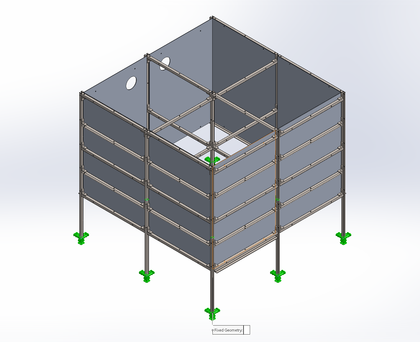
Fixed Constraints for the Unistrut Supports – Click to Enlarge
RESULTS AND DISCUSSION
This section presents the findings from both the analytical hand calculations and the finite element analysis simulations conducted on the Unistrut support assembly. The results are organized into three areas: stress analysis, deflection analysis, and factor of safety evaluation. Each area is assessed against recognized engineering limits to confirm whether the structure meets the required serviceability and strength criteria under the full 2,300 kg operational load. Both simulation configurations, the all-Stainless Steel 316 design and the hybrid SS-316 and AL-6061 design, were evaluated. The results demonstrate that the all-steel configuration satisfies all structural requirements, while the hybrid configuration provides useful weight savings data despite its localized FOS limitations.
STRESS ANALYSIS
Stress analysis is a branch of engineering that predicts how a physical structure will respond to external forces by calculating internal resistances called stresses. These calculations determine if a material can withstand a specific load without experiencing permanent deformation (yielding) or structural failure.
The analysis begins by establishing the Total Factored Vertical Force, which represents the total downward load the structure must resist. In simple terms, this vertical force is equal to the combined weight of the structural assembly and the maximum waste accumulation. By calculating this force first, I can derive the internal bending moments required to check the material limits of the Unistrut members.
TOTAL FACTORED VERTICAL FORCE
The total factored vertical force is calculated by multiplying the maximum design mass of 2,300 kg by the gravitational acceleration of 9.81 m/s2, giving a total downward force of 22,563 N acting on the assembly.
Wtotal = mass × gravitational acceleration
Wtotal = (2300 kg)(9.81 m/s2) = 22,563 N
The maximum bending stress in the governing Unistrut member was then calculated using classical beam theory, where the maximum bending moment for a simply supported beam under a uniformly distributed load is used to verify that the material’s elastic limit is not exceeded under the applied loads.
DEFLECTION ANALYSIS
The structural serviceability was evaluated by calculating the maximum expected deformation under the full operational load using the Euler-Bernoulli Beam Theory. In words, this theorem states that the maximum deflection is directly proportional to the total load and the fourth power of the length of the span, while being inversely proportional to the stiffness of the material (E) and the geometric cross-section (I) of the member. By using this relationship, I was able to predict how much the Unistrut frame would bow under the 2,300 kg mass and compare that result to my FEA simulation to ensure the design remains within safe limits.
The maximum deflection (δmax) is equal to five times the distributed load (w) per unit length (L) multiplied by the span length raised to the fourth power, divided by three hundred and eighty-four times the elastic modulus (E) multiplied by the second moment of area (I) of the cross-section.
δmax =
5wL4384EI
where :
- w (Uniform Load) represents the distributed vertical force across the span.
- L (Length) is the effective span of the governing cross-member identified in the simulation.
- E (Elastic Modulus) = 200 GPa.
- I (Second Moment of Area) = second moment of area of the Unistrut section.
The analytically calculated deflection was of the same order of magnitude as the maximum FEA displacement, approximately 1.68 mm, confirming good agreement between the analytical and numerical methods.
SIMULATION 1: ALL-STAINLESS STEEL 316 CONFIGURATION
The first simulation modeled the entire Unistrut assembly using Stainless Steel 316 for all structural members. The image below shows the Von Mises stress distribution across the structure under the combined gravity and distributed mass loading. The color gradient indicates stress concentration zones, with the highest values appearing at the most critical load-transfer regions such as mid-span locations and primary connection points.
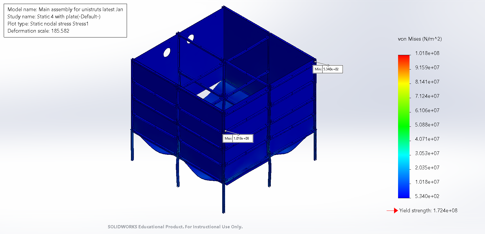
Figure 5: Von Mises stress distribution for the all-Stainless Steel 316 configuration – Click to Enlarge
In this simulation, the maximum Von Mises stress was recorded at 101.8 MPa, against a material yield strength of 172.36 MPa. The resulting Factor of Safety was calculated at 1.7, confirming that the maximum internal stress does not exceed the material’s elastic limit and that the design remains structurally sufficient for the required load conditions.
SIMULATION 2: HYBRID (SS-316 & AL-6061) CONFIGURATION
The second simulation modeled a hybrid configuration using Stainless Steel 316 for primary load-carrying members and Aluminum 6061 for secondary members. The image below shows the resulting Von Mises stress distribution, demonstrating how the highest operational stresses are directed into the primary steel members, while aluminum components carry reduced loads in lower-stress regions.
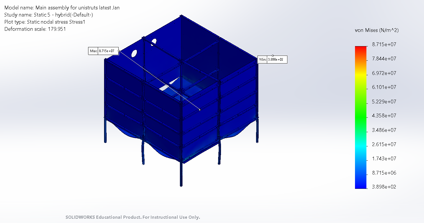
Figure 6: Von Mises stress distribution for the hybrid configuration – Click to Enlarge
In the hybrid simulation, the maximum Von Mises stress was recorded at 87.1 MPa. This configuration successfully directs the highest operational stresses into the primary stainless steel members, utilizing their superior ultimate tensile strength to support the main load paths. While localized numerical peaks remain visible at specific steel-to-aluminum connection points, the overall structural integrity is maintained through this strategic material placement.
DEFLECTION LIMITS
The deflection analysis was conducted to confirm that the Unistrut frame satisfies serviceability requirements and does not experience excessive deformation under the applied gravity and distributed mass loading. From the finite element analysis, the maximum resultant displacement observed in the structure was:
δmax = 1.683 mm
To assess acceptability, this FEA deflection result was compared against standard allowable deflection limits commonly used for structural frame members. Two allowable deflection thresholds were calculated using the effective span length (L) of the governing horizontal cross-member identified in the FEA simulation:
- L/240 – Represents the typical allowable deflection limit for general structural frame members under standard loading conditions.
- L/360 – Provides a conservative check for applications requiring tightly controlled deformation.
Where L is the effective span of the governing cross-member identified in the simulation. The structure is considered acceptable in terms of serviceability if the maximum FEA deflection (δmax) does not exceed the allowable limit (δallow), expressed as:
δmax ≤ δallow
DEFLECTION UTILIZATION RATIO
The final serviceability check is expressed through the Deflection Utilization Ratio (UR). This value represents the ratio of the actual maximum displacement (δmax) observed in the simulation to the maximum allowable displacement (δallow) permitted by engineering standards. A utilization ratio less than or equal to unity indicates that the deflection limit is satisfied:
UR =
δmaxδallow
Based on this comparison, the maximum deflection obtained from the FEA is within acceptable limits for both the L/240 and L/360 criteria, confirming that the Unistrut frame meets the deflection serviceability requirements under the applied loading conditions.
FACTOR OF SAFETY
The factor of safety (FOS) of the Unistrut frame was evaluated by comparing the maximum Von Mises stress from the FEA results with the yield strength of the assigned structural material. This comparison ensures that the assembly remains safely within the elastic range of the specified material under the full operational load.
From Simulation 1, the following stress and material strength (σvm, max) values were recorded:
σvm,max = 1.081 × 10⁸ Pa = 108.1 MPa
The yield strength (σy) used in the study was:
σy = 1.724 × 10⁸ Pa = 172 MPa
The yield strength value was obtained from the material properties of Stainless Steel 316 as assigned within the SolidWorks Simulation material database. It was used as the reference limit for all factor of safety calculations. The structural safety margin is quantified using the Factor of Safety (FOS), which compares the material limits to the maximum operational stress identified in the simulation. This ratio ensures that the assembly remains safely within the elastic range of the specified material:
FOS =
σyσvm,max
=
172108.1
= 1.7
Under the 2,300 kg load, the primary SS-316 components achieve a Factor of Safety of 1.7. Since this value is greater than 1.0, it confirms that the design is safe for operation under the specified loading conditions and that no yielding of the primary structural members is expected.
CONCLUSION
The structural analysis of the Unistrut support assembly confirms that the all-Stainless Steel 316 configuration satisfies both strength and serviceability requirements under the maximum operational load of 2,300 kg. The FEA results and analytical hand calculations are in good agreement, with the maximum deflection remaining within the conservative L/360 serviceability limit and the primary structural members maintaining a Factor of Safety of 1.7 above the material yield strength.
While the structure has a theoretical failure limit of 3,910 kg, standard engineering practice for static assemblies requires maintaining a Factor of Safety of at least 1.5. To ensure long-term structural integrity and account for the 2,260.8 kg total unprocessed mass expected at the 6-month mark, a Safe Working Load (SWL) of 2,600 kg is recommended. This capacity provides a sufficient buffer for the vermiculture process to handle unexpected weight increases or minor dynamic loading events without exceeding the material yield limits of the Stainless Steel frame.
The hybrid configuration, while achieving a 35% reduction in self-weight of approximately 1,251 lbs, was found to produce localized factor of safety failures at connection points due to the significantly lower yield strength of Aluminum 6061 at 55.14 MPa compared to Stainless Steel 316 at 172.36 MPa. As a result, the all-Stainless Steel 316 configuration is the recommended design for the final installation.
FREQUENTLY ANSWERED QUESTIONS (FAQ)
Why Was a Factor of Safety of 1.5 Chosen as the Minimum Acceptable Value?
A minimum Factor of Safety of 1.5 is standard engineering practice for static structural assemblies. It accounts for real-world variability in material properties, load estimation accuracy, and long-term wear or fatigue. This value ensures that the structure can tolerate minor unexpected load increases without risk of yielding or structural failure.
Why Was the Hybrid Configuration Not Used Despite Its Weight Savings?
Although the hybrid configuration reduced total assembly weight by approximately 35%, the Aluminum 6061 secondary members could not sustain the localized stresses at the connection points under the full 2,300 kg load. The yield strength of Aluminum 6061 at 55.14 MPa is approximately three times lower than that of Stainless Steel 316 at 172.36 MPa, making it the weakest link in the load path. Additionally, joining dissimilar metals introduces galvanic corrosion risk and requires specialized hardware, which increases long-term maintenance costs.
What Is the Difference Between the L/240 and L/360 Deflection Limits?
Both limits are span-based serviceability criteria used in structural engineering. L/240 is the standard allowable deflection limit for general structural frame members under normal loading conditions. L/360 is a more conservative threshold used when tighter deformation control is required. In this study, both limits were evaluated, and the Unistrut frame satisfied both criteria.
What Does the Deflection Utilization Ratio Tell Us?
The Deflection Utilization Ratio (UR) quantifies how close the actual deflection is to the allowable limit. A value of 1.0 means the structure is exactly at the limit, while a value below 1.0 means the structure has remaining deflection capacity. A UR well below 1.0 indicates a conservative and serviceable design. In this study, the UR confirmed that the Unistrut frame deforms well within acceptable bounds under the full operational load.
Can the Safe Working Load Be Exceeded Temporarily?
The Safe Working Load of 2,600 kg is the maximum load the structure should carry under normal operating conditions. While the theoretical failure limit is 3,910 kg, exceeding the SWL even temporarily reduces the safety margin and increases the risk of fatigue, joint loosening, and long-term deformation. Any load above the SWL must be assessed by a qualified structural engineer before the assembly is used.
Why Is Stainless Steel 316 Used Instead of a More Common Grade Such as Mild Steel?
Stainless Steel 316 was selected for its superior corrosion resistance, particularly in environments exposed to moisture and organic material, both of which are present in a vermiculture system. Mild steel would corrode rapidly under these conditions, compromising structural integrity over time. The higher initial material cost of SS-316 is offset by its longer service life and reduced maintenance requirements in this application.
SLIDER DESIGN & CALCULATIONS
In this analysis, we evaluate the forces acting on a slider used in a compost processing system. The slider, an integral component designed to separate compost from the batch, is driven into a vertical pile of human waste compost using a sledgehammer. After the compost is processed and ready for removal, the slider is pulled out using a winch.
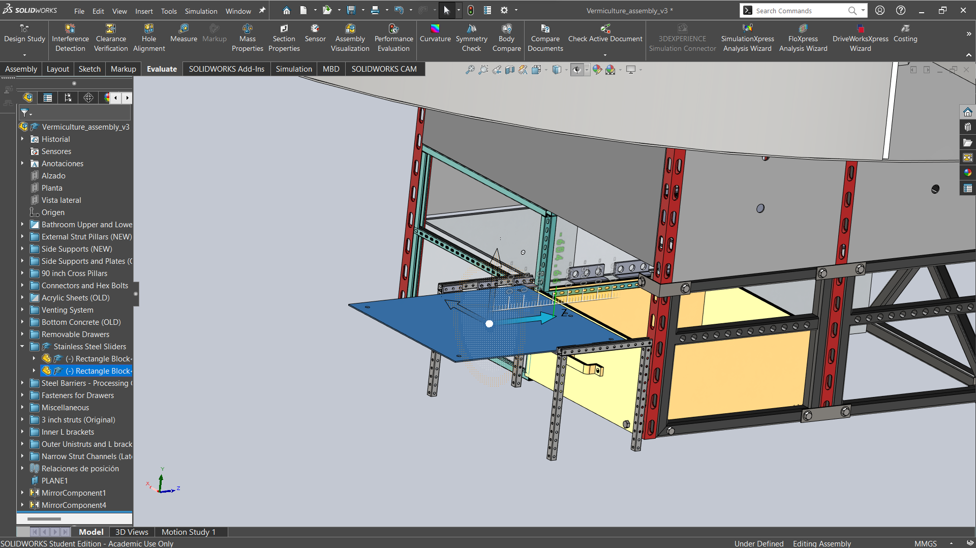
Vermiculture Separation-Slider Being Inserted – Click to Enlarge
To ensure the slider can withstand the rigorous demands of this process, we performed various calculations, including impact force from the hammer during insertion and tensile forces from the winch during extraction. These calculations, along with a detailed Finite Element Analysis (FEA), ensure that the slider is robust enough to handle both the impact and pulling forces, maintaining reliable performance during compost separation.
This section discusses this with the following:
- Calculations and FEA of Hammer Impact on Slider
- Hammer Impact on Slider Assumptions and Resources
- Proper and Assumed Use of Component
- Calculation for Force Applied During Hammer Swing
- Hammer Swing Results Summary
- Calculations for Resistance
- Calculations for Resistance Results Summary
- Calculations for Force Applied
- Calculation for Net Force
- Calculation for Net Force Results Summary
- Force Calculation for Partial Swing
- Force Calculation for Partial Swing Results Summary
- FEA Analysis and Results
- Reinforced Slider FEA and Results
- Reinforced Slider FEA and Results Summary
- Hammer Impact on Slider Final Summary
- Calculations and FEA of Winch Pulling Slider Out
CALCULATIONS AND FEA OF HAMMER IMPACT ON SLIDER
In this analysis, we focus on determining the force exerted on the slider during impact when it is hammered into a vertical pile of human waste compost. The slider, designed to aid in the separation of compost from the batch in the drawer to be emptied, must be securely driven into place using a sledgehammer. To ensure the slider can withstand the force of the hammer without failure, we performed calculations to estimate the impact force generated during this process. These calculations are critical for assessing the durability of the slider under repeated hammer strikes, ensuring its longevity and reliability in the composting system.
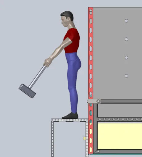
Representation of a Person Hammering the Slider
HAMMER IMPACT ON SLIDER ASSUMPTIONS AND RESOURCES
- Mass of hammer: 5kg (Source: Eurafco Online Shop – ‘GEDORE Sledge Hammer’)
- Length of Hammer: 0.5m (Source: Eurafco Online Shop – ‘GEDORE Sledge Hammer’)
- Height from which hammer is swung: (Source: First In Architecture – ‘Average Male and Female Dimensions and Heights’)
- Avg human height + length of hammer = 2m + 0.5m = 2.5m
- Density of steel: 7,850 kg/m3 (Buy A Beam – ‘What is the Density of Steel?’)
- Coefficient of friction:
- For this calculation, the slider is in contact with two different materials. The steel L-brackets on which the slider rests and the compost which would be resting on top. For a more accurate result, the higher of the two were chosen (steel-on-steel) since the slider would be pressed against the L-bracket while it is being pulled out.
- Coefficient of friction (μ) for steel-on-steel: 0.7 (Source: Engineering Toolbox – ‘Frictions Coefficients and Calculator’)
- All engineering formulae from: Tyler. G. Hicks, PE – ‘Mechanical Engineering Formulas Pocket Reference’
- Hammer swing velocity estimation: UNSW, School of Physics – ‘Smashing bricks and the ballistic pendulum: more collision examples’
- Male vs female strength comparison: National Library of Medicine – ‘A Comparison between Male and Female Athletes in Relative Strength and Power Performances’
- Estimation for factor of safety for buildings: Wikipedia – Factor of Safety
PROPER (AND ASSUMED) USE OF COMPONENT
Here’s a video showing how to hammer to protect a person’s back and feet while maximizing the slider’s longevity by maintaining a consistent strike zone and angle of impact.
- Always wear eye protection, proper footwear, and gloves
- Always swing with two hands
- Make sure the removable slider support structure is properly attached
- Use proper lifting/swinging form to avoid back strain
- Never stand on the slider
VIDEO COMING: HOW TO PROPERLY HAMMER IN THE SLIDER FOR MAXIMUM SAFETY AND LONGEVITY
SEE OUR HOW TO HELP AND/OR CROWDFUNDING CAMPAIGN PAGE TO HELP CREATE ALL THE TUTORIAL VIDEOS FASTER
CALCULATION FOR FORCE APPLIED DURING HAMMER SWING
In this section, the force exerted by a person swinging the sledgehammer is calculated. Based on past recorded experiments[7], the velocity of a hammer (2kg) swung by an average adult female is ~4m/s. Hence, the force exerted by the person to accelerate the hammer to this speed over a 0.5m distance can be calculated by solving for ‘F’ from the equation for work, i.e work, ‘W’ is equal to the force, ‘F’ multiplied by the distance, ‘d’. Hence,
Given:
- Mass, ‘m’ = 2 kg
- Velocity, ‘v’ = 4 m/s
- Distance, ‘d’ = 0.5 m
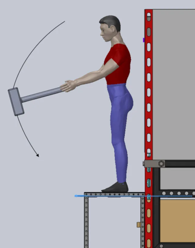
Representation of a Person Hammering the Slider with Swing Direction
The kinetic energy for a speed of 4 m/s is:
KE = (mv2) ÷ 2
= (2 × (4)2) ÷ 2
= 16 J
Using the work equation mentioned earlier, work, ‘W,’ is equal to the force, ‘F,’ multiplied by the distance, ‘d’.
W = F × d
Substituting the values:
F × 0.5 m = 16 J
Solving F:
F = 16 J ÷ 0.5 m = 32 N
Considering that an average adult male would be 60% stronger compared to a female[8], the force applied in a similar scenario by a male would be:
F = 32 N × 1.6 = 51.2 N
Considering a factor of safety of 2 for the calculation[9]:
F = 51.2 N × 2 = 104.2 N
HAMMER SWING RESULTS SUMMARY
The calculated force applied during a hammer swing by an average adult female is 32 N, while an adult male exerts 51.2 N. With a safety factor of 2.0, the final force that would be exerted by an adult male to swing the hammer is 104.2 N, which forms the basis for subsequent force and impact analysis.
CALCULATIONS FOR RESISTANCE
In this section, the resistance force encountered by a steel plate as it is driven into a compost pile is calculated.
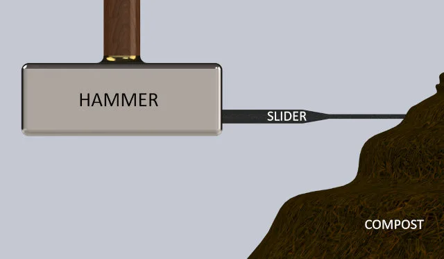
Figure – Shows a Representation of how the Slider Would be Hammered into the Compost
The frictional forces at different depths are evaluated based on the mass and density of the compost and the frictional resistance between the steel plate and the L-brackets.
To calculate the resistance force, first we need to calculate the mass of the steel plate.
Given:
- Plate width = 46 in = 1.17m
- Plate thickness = 0.25 in = 0.00635 m
- Density of steel ρsteel = 7,850 kg/m3 [4]
The plate is of a square cross-section and the volume ‘V’ is equal to the square of the width multiplied by the thickness.
V = width × width × thickness
= 1.17 m × 1.17 m × 0.00635 m = 0.00873 m3
The mass ‘m’ is equal to the density of steel times the volume:
m = ρsteel × V
= 7,850 kg/m3 × 0.00873 m3 = 68.51 kg
Weight of plate,
W = mass × acceleration due to gravity
= 68.51 kg × 9.81 m/s2 = 672.91 N
Mass of Compost = 673.85 kg (from previous calculations)
Weight of compost
Wcompost = 673.85 kg × 9.81 m/s2 = 6,608.43 N
As the plate is hammered into the compost pile, the mass acting on the plate gradually increases, thereby increasing the friction between the plate and the L-bracket.
Hence, assuming that the compost mass increases linearly with the depth of insertion, the weight of compost at depth ‘d’:
Wcompost(d) = (d ÷ h) × Wcompost
Where:
- h = 1.17 m
- Wcompost = 6,608.43 N
Therefore:
Wcompost(d) = ((d × 6,608.43) ÷ 1.17)
Now, we calculate the friction force as a function of depth d, considering the gradual increase in compost weight.
Given:
- Coefficient of friction μ = 0.7 [5]
Total weight acting on the plate,
Wtotal(d) = Wplate + Wcompost(d)
= 672.91 + ((d × 6,608.43) ÷ 1.17)
Calculating the frictional force as a function of depth,
Ffriction(d) = μ × Wtotal(d)
= 0.7 × (672.91 + ((d × 6,608.43) ÷ 1.17))
= 0.7 × (672.91 + 5,648.24d)
= 471.04 + 3,953.77d
CALCULATIONS FOR RESISTANCE RESULTS SUMMARY
Due to the increase in surface area of the slider on which the compost rests as it is driven deeper, there will be a linear increase in the frictional resistance encountered by the slider. With the coefficient of friction at 0.7 (steel-on-steel), the value of this resisting force can be calculated as a function of the insertion depth ‘d’. This allows us to calculate the value of the frictional force at different values for insertion depth ‘d’.
CALCULATIONS FOR FORCE APPLIED
This section shows the calculations for impact force applied during a hammer swing to drive the plate into compost.
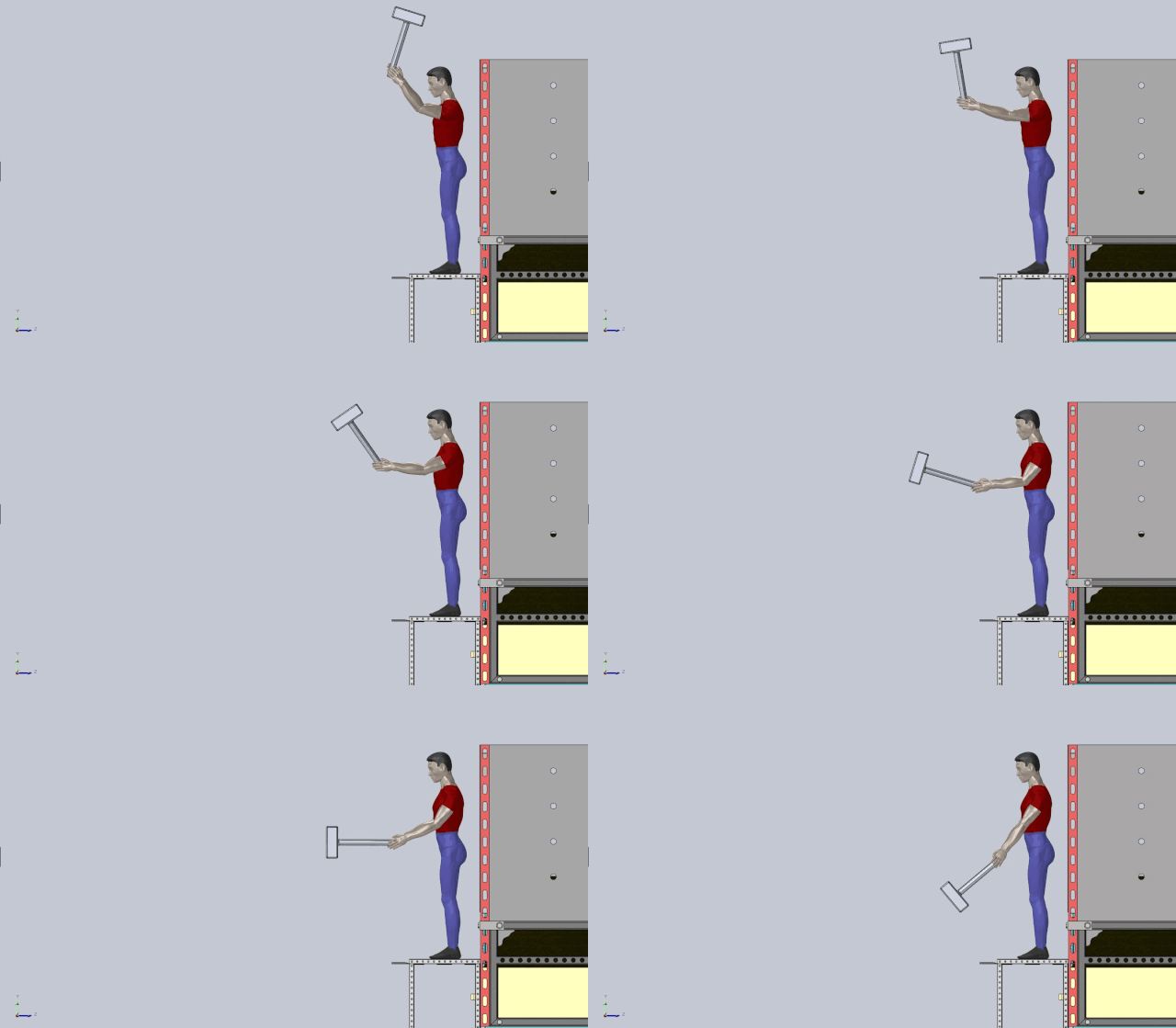
Animation of Hammer Swing
The force and velocity at impact are calculated based on a 5 kg sledgehammer and a 2.5-meter swing[1][2][3].
Work done by the force is equal to the force ‘F’ times the swing distance ‘d’:
W = F × d
Where:
Substituting the values:
W = 104.2 × 2.5
= 260.5 J
Since the work done on the hammer is completely converted into kinetic energy, we equate to the equation of kinetic energy, mass times the square of the velocity divided by two, as shown below:
W = K.E = (mv2) ÷ 2
260.5 = (5 × v2) ÷ 2
v = 10.2 m/s
This estimated value of velocity is similar to the maximum possible swing velocity by an average adult that is mentioned in UNSW, School of Physics – ‘Smashing Bricks and the Ballistic Pendulum: More Collision Examples’.
Based on the impulse-momentum theorem, the impact force ‘F’ is equal to the mass ‘m’ times the velocity ‘v’, divided by the impact time ‘t’:
F = mv/t
Where:
- m = 5 kg, mass of the sledgehammer[1]
- v = 10.2 m/s, velocity at impact
- t = 0.01 s, estimated impact time
Substituting the values:
F = (5 × 10.2) ÷ 0.01
= 51 ÷ 0.01
= 5,100 N
CALCULATIONS FOR FORCE APPLIED RESULTS SUMMARY
The work done by the hammer’s impact was found to be 260.5 J, which translates to a velocity of 10.2 m/s at the moment of impact. This velocity was used to calculate the force of impact, which was 5,100 N, indicating the hammer’s potential to drive the plate into the compost as shown in the net force calculation below.
CALCULATION FOR NET FORCE
Here, the force needed to overcome friction and drive the plate fully into the compost is calculated. The net force applied at various depths is considered, including the reduction of force as the plate sinks deeper into the compost.
Now to calculate the net force driving the plate into the compost:
Impact force,
Fimpact = 5,100 N
Frictional force,
Ffriction(d) = 471.04 + 3,953.77d
The net force at any depth (length of plate inserted into) ‘d’ is:
Fnet(d) = Fimpact – Ffriction(d)
= 5100 – (471.04 + 3,953.77d)
= 5100 – 471.04 – 3,953.77d
= 4,628.96 – 3,953.77d
Net Force at Key Depths:
Initial Stage d = 0
Fnet(0) = 4,628.96 N
At the start, the net force is positive, so the plate will move easily.
Halfway inserted, d = 0.585 m
Fnet(0.585) = 4,628.96 – (3,953.77 × 0.585)
= 2,491.50 N
At halfway insertion, the net force is still positive, but it is much lower.
At full insertion, d = 1.17m
Fnet(1.17) = 4,628.96 – (3,953.77 × 1.17)
= 4,628.96 – 4,625.91
= 3.04 N
This shows that the force from the hammer swing will be sufficient to insert the plate completely.
CALCULATION FOR NET FORCE RESULTS SUMMARY
At the initial stage, the net force driving the plate is 4,628.96 N. As the plate is driven deeper into the compost, the frictional resistance increases, reducing the net force. At full insertion, the net force becomes 3.04 N, meaning the hammer impact is sufficient to fully drive the plate into the compost.
FORCE CALCULATION FOR PARTIAL SWING
For this calculation, we consider the wide stance a person takes while standing atop the slider and the limited height to which the hammer can be swung.
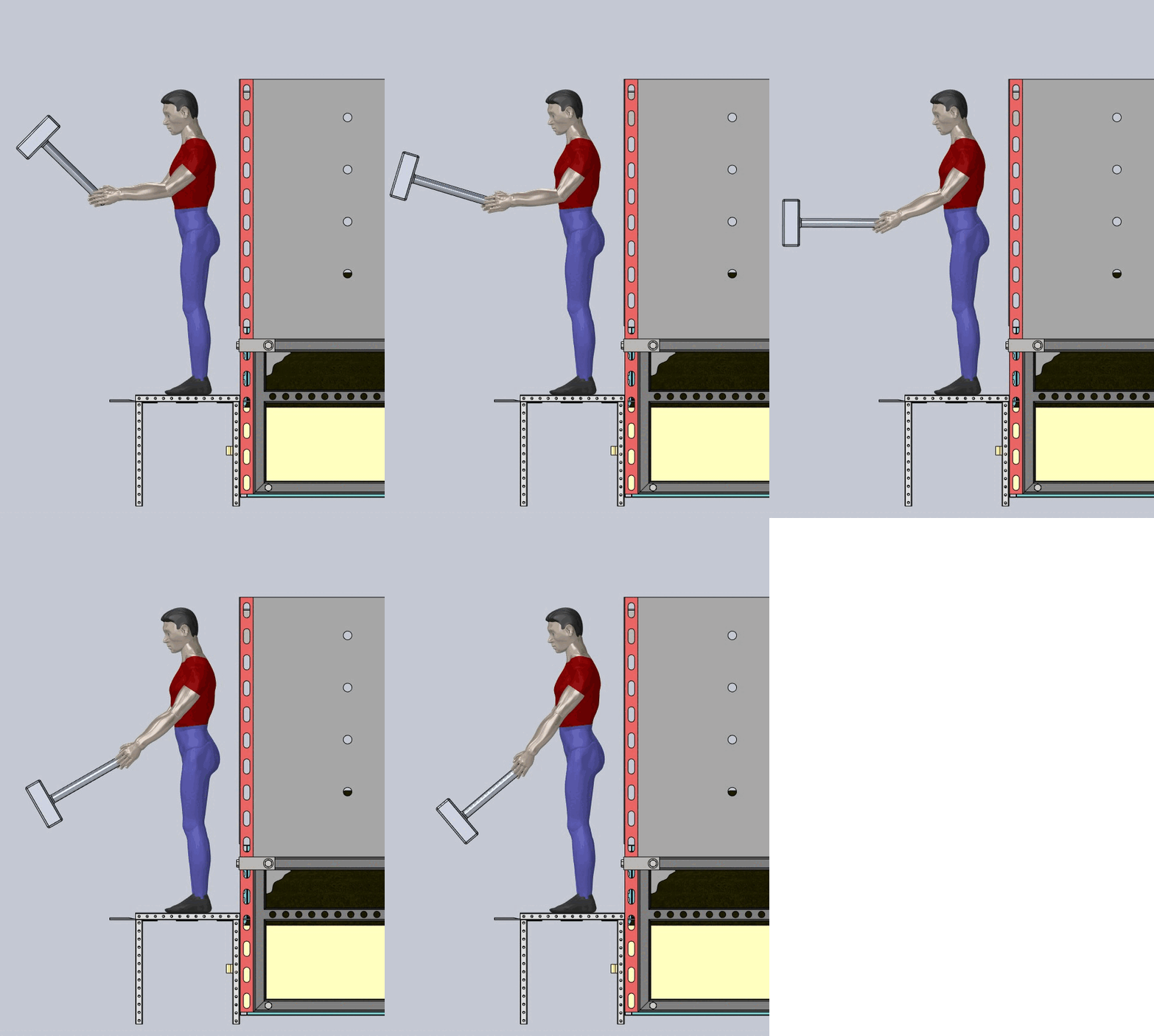
Animation of a Partial Hammer Swing (
The impact force of a hammer when swung at a reduced height of 2 meters is hence calculated, analyzing the effect of partial swings on the force applied and plate insertion depth.
Work, ‘W’ is equal to the force ‘F’ times the swing distance ‘d’:
W = F × d
Where:
- F = 104.2 N
- d = 2.0 m, after adjustments
Substituting the values:
W = 104.2 N × 2 m
= 208.4 J
Since the work done on the hammer is completely converted into kinetic energy, we equate to the formula for kinetic energy, which is mass ‘m’ times the square of the velocity ‘v’ divided by two as shown below:
W = K.E = (mv2) ÷ 2
Where:
- m = 5 kg (mass of the sledgehammer)
208.4 = (5 × v2) ÷ 2
v = 9.13 m/s
Based on the impulse-momentum theorem, the impact force ‘F’ is equal to the mass ‘m’ times the velocity ‘v’, divided by the impact time ‘t’:
F = mv ÷ t
Where:
- m = 5 kg (mass of the sledgehammer)
- v = 9.13 m/s (velocity at impact)
- t = 0.01 s (estimated impact time)
Substituting the values:
Fimpact = (5 × 9.13) ÷ 0.01
= 45.65 ÷ 0.01
= 4,565 N
The equation for net force at depth ‘d’:
Fnet(d) = Fimpact – 471.04 + 3,953.77d
= 4,565 – 471.04 + 3,953.77d
= 4,093.96 + 3,953.77d
If Fnet(d) = 0,
4,093.96 + 3,953.77d = 0 N
Solving for d,
d = 1.03 m
This means that the impact force at a height of 2 m will drive the slider in by 1.03 m.
FORCE CALCULATION FOR PARTIAL SWING RESULTS SUMMARY
For a partial swing, the impact force decreases to 4,565 N from 5,100 N, resulting in a maximum insertion depth of 1.03 meters. This demonstrates that while a partial swing generates sufficient force, it does not drive the plate as deep into the compost compared to a full swing (1.17m).
FEA ANALYSIS AND RESULTS
To analyze the effects of this 5,100 N force on a steel surface, we conducted a finite element analysis (FEA) by keeping three edges of the plate fixed as shown below.
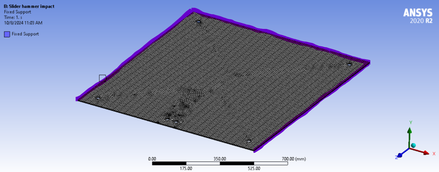
Meshed slider with fixed edges (purple highlight) – Click to Enlarge
This is done to calculate the effect of the maximum force applied on the plate during a hammer impact. The results indicated a maximum deformation of 0.009 mm, showing the material is highly resistant to deformation under this load.
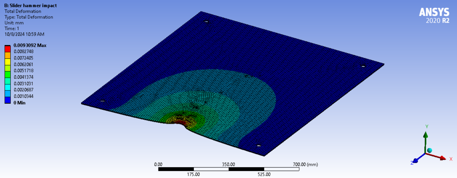
FEA result – Total Deformation – Click to Enlarge
The maximum von Mises stress was 18.67 MPa, well below the yield strength of typical structural steel (approximately 250 MPa), indicating no risk of material failure.
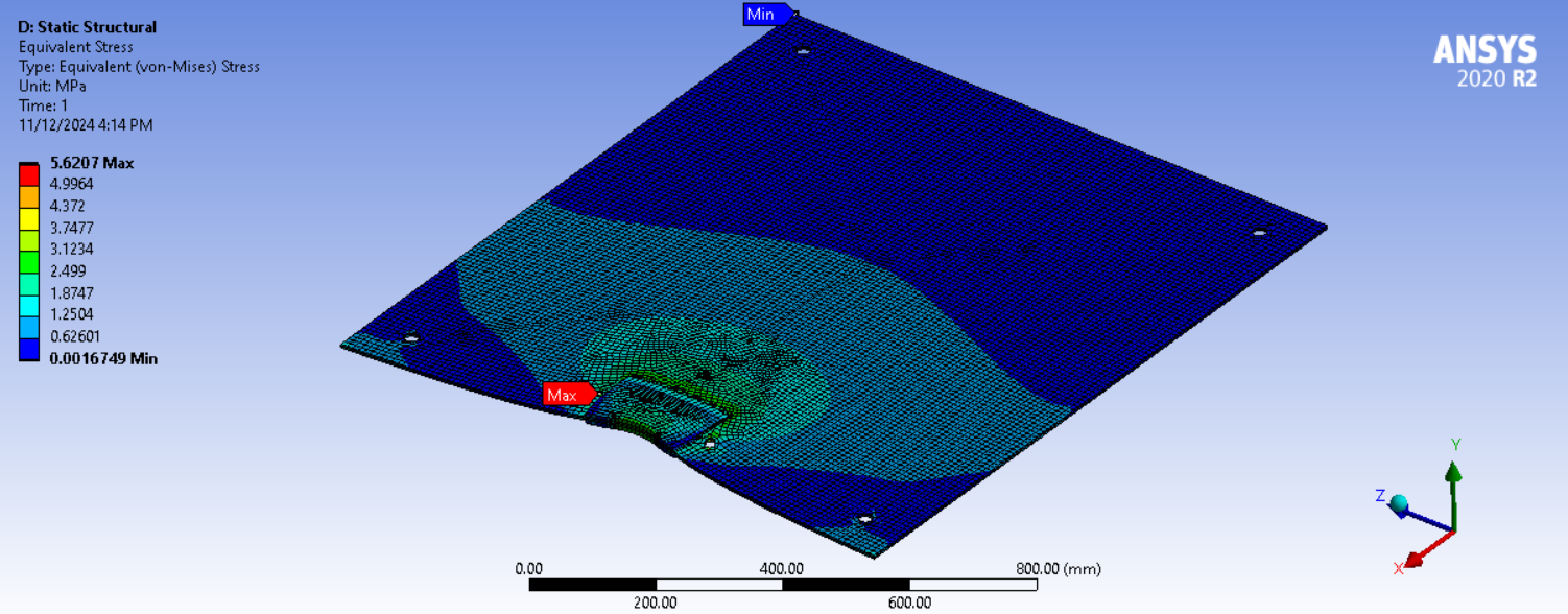
FEA result – Equivalent (von-Mises) Stress – Click to Enlarge
The stress-strain curve for this analysis confirms that the steel plate remains within its elastic limit under the applied force. Since the maximum von Mises stress (18.67 MPa) is significantly below the yield strength of typical structural steel (approximately 250 MPa), the material behavior observed is elastic. This means that upon removal of the applied force, the plate would return to its original shape without any permanent deformation.
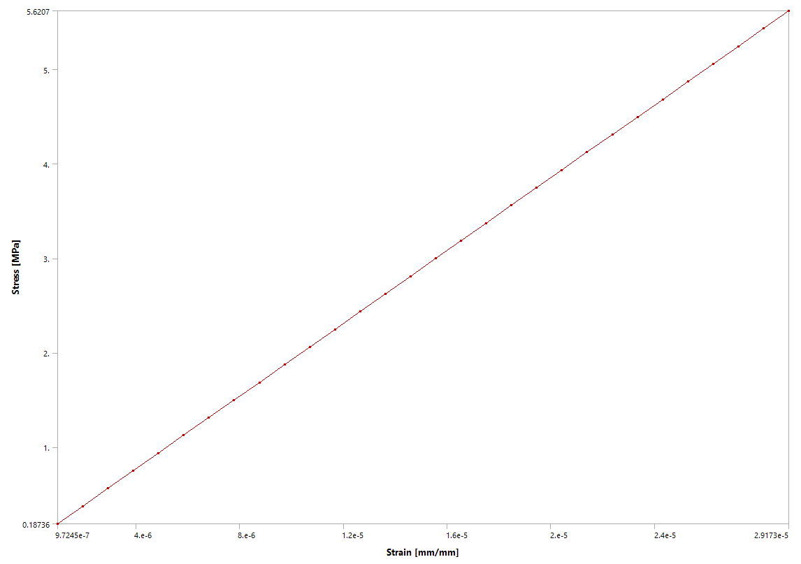
Stress-Strain Curve – Click to Enlarge
The maximum strain observed was 2.9173e-5, which aligns with the material’s elastic response. In the stress-strain curve, this point falls within the linear portion, where stress is directly proportional to strain, following Hooke’s law. This elasticity indicates that the steel plate can withstand the impact load without compromising structural integrity or undergoing plastic deformation.
FEA ANALYSIS AND RESULTS SUMMARY
In summary, the force exerted by the sledgehammer was calculated to be 5,100 N. The FEA results confirmed that the steel material would experience minimal deformation and low stress levels, ensuring that it can safely withstand the impact without yielding or failure. The design is robust and structurally sound for the given loading condition.
REINFORCED SLIDER FEA AND RESULTS
Due to the slider plate’s quarter-inch thickness, concerns arose regarding its susceptibility to deformation and wear under repeated hammering. To mitigate these issues, an alternative design incorporating additional reinforcements was developed, offering a larger and more durable strike zone.
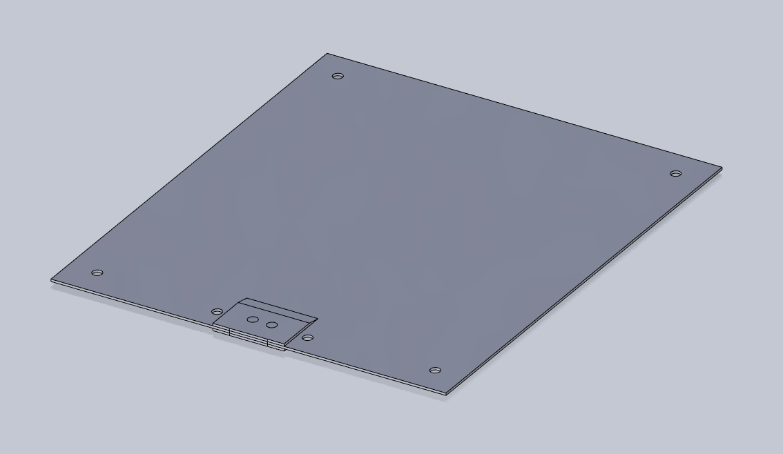
Redesigned Slider with a Larger Impact Zone – Click to Enlarge
A detailed finite element analysis (FEA) was performed on the revised design, using identical boundary conditions as the original study. The findings of this analysis are presented below, highlighting the improvements in structural integrity and performance.
REINFORCED SLIDER FEA AND RESULTS SUMMARY
The updated analysis shows a significant improvement in both deformation and stress. Deformation has been minimized to 0.005 mm from 0.009 mm, indicating improved structural stability and a stronger resistance to operational demands.
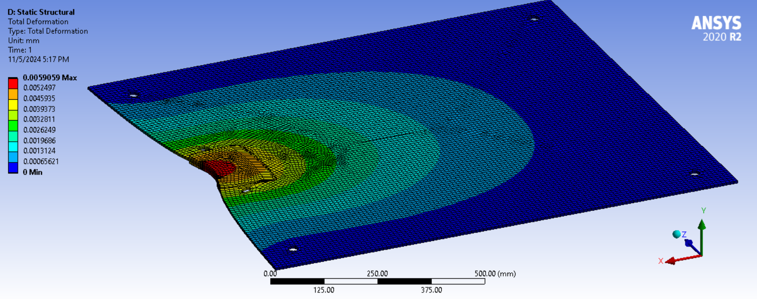
FEA result – Total Deformation (Redesign) – Click to Enlarge
Meanwhile, von Mises stress has been reduced to 3.0MPa, enhancing the component’s durability and reducing the likelihood of material fatigue over time.
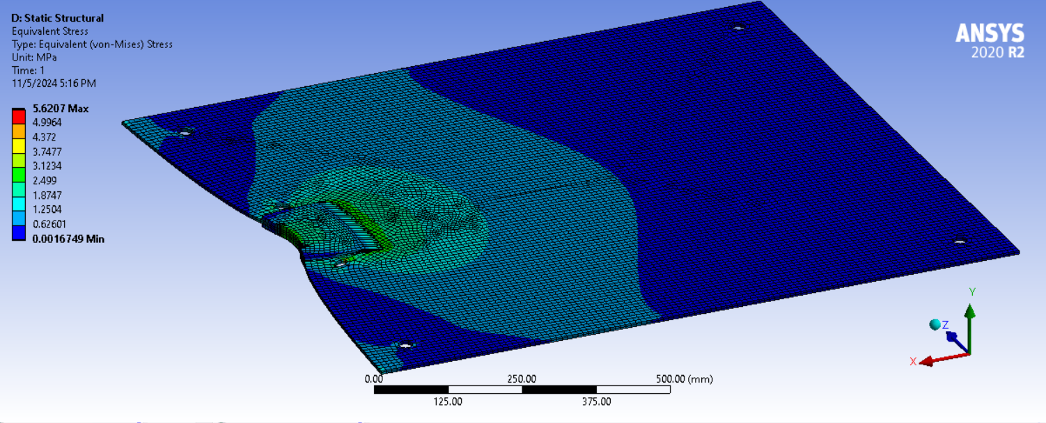
FEA result – Equivalent (von-Mises) Stress (Redesign) – Click to Enlarge
Additionally, the expanded strike zone boosts usability, providing a larger target area that allows users to more easily and accurately hammer the slider while standing on the support structure. These enhancements collectively contribute to improved operator convenience, efficiency, and safety.
HAMMER IMPACT ON SLIDER FINAL SUMMARY
This analysis evaluated the forces on a slider used in a compost processing system, where it was driven into compost using a 5 kg sledgehammer and later extracted by a winch. The hammer impact force was calculated to be 5,100 N, more than enough to overcome the frictional resistance that builds as the slider sinks deeper into the compost. The frictional force, which increases with depth due to the weight of compost pressing against the steel slider, was calculated as a function of depth, reaching a maximum of 4,625.91 N at full insertion (1.17 m). At the start of insertion, the net force exerted on the slider by the hammer impact was 4,628.96 N, allowing the slider to move easily, and by the time it got fully inserted, the net force dropped to just 3.04 N.
Finite Element Analysis (FEA) was conducted to confirm the slider’s ability to withstand these forces without failure. The analysis showed minimal deformation (0.009 mm) and a maximum von Mises stress of 18.67 MPa, well below the steel’s yield strength of 250 MPa. In a reinforced version of the slider, deformation was reduced further to 0.005 mm, and stress levels dropped to 3 MPa. The hammer’s impact force was sufficient to overcome the increasing frictional resistance, ensuring reliable slider insertion.
CALCULATIONS AND FEA OF WINCH PULLING SLIDER OUT
This section examines the tensile forces applied to the slider during its removal from the compost pile using a winch. The slider, after serving its purpose in the compost separation process, is extracted by applying a pulling force. To evaluate the slider’s ability to endure this process without damage, we conducted calculations to estimate the force exerted by the winch during extraction. These calculations, verified using finite element analysis (FEA) software, are essential for determining whether the slider can withstand the pulling forces while maintaining its structural integrity, ensuring efficient and safe operation during the compost removal process.
WINCH PULLING CALCULATIONS ASSUMPTIONS AND RESOURCES
Here’s a video demonstration of how to safely and effectively use the winch to extract the slider from the compost pile, ensuring both user safety and the longevity of the equipment.
- Always inspect the winch and slider before use: Ensure all components, including the winch cable and attachment points, are in good condition. Replace any damaged parts before operation.
- Wear appropriate safety gear: Eye protection, gloves, and sturdy footwear are mandatory to protect against debris or accidental equipment failure.
- Securely attach the winch cable: Confirm the winch cable is properly attached to the slider using the designated attachment points to prevent slippage during operation.
- Use controlled winch operation: Apply steady, controlled pulling forces to avoid sudden jerks that may compromise the slider’s structural integrity. Ensure the winch is never overloaded.
- Clear the area of obstacles: Ensure no obstructions or bystanders are in the path of the slider as it is being pulled out.
VIDEO COMING: HOW TO PROPERLY AND SAFELY REMOVE THE SLIDER
SEE OUR HOW TO HELP AND/OR CROWDFUNDING CAMPAIGN PAGE TO HELP CREATE ALL THE TUTORIAL VIDEOS FASTER
WINCH PULLING CALCULATIONS ASSUMPTIONS AND RESOURCES
- Total weight of material resting on top: 673.85 kg (from previous calculations)
- Coefficient of friction:
- For this calculation, the slider is in contact with two different materials. The steel L-brackets on which the slider rests and the compost which would be resting on top. For a more accurate result, the higher of the two were chosen (steel-on-steel) since the slider would be pressed against the L-bracket while it is being pulled out.
- Coefficient of friction (μ) for steel-on-steel: 0.7 (Source: Engineering Toolbox – ‘Frictions Coefficients and Calculator’)
- Area of the plate: 1.244 m² (from previous calculations)
WINCH PULLING CALCULATIONS
The calculation determines the forces acting on a slider plate subjected to the weight of compost and friction during horizontal movement. First, the gravitational force exerted by the compost on the plate is calculated using Fgravity = m × g, where the compost mass m = 673.85 kg and gravitational acceleration g = 9.81 m/s2, resulting in a force of 6,610.44 N. To overcome the friction between the slider and the L-brackets (assumed steel-on-steel contact with a coefficient of friction μ = 0.7), the required horizontal pulling force is found using Fhorizontal = μ × Fgravity, yielding 4,627.31 N. This force is also exerted on the inner side of the hole where the pulling hook is attached. The effects of this horizontal force on the slider plate were further analyzed through finite element analysis (FEA).
Using these values, the calculations were performed as follows:
The gravitational force acting on the plate due to the weight of the compost was calculated using the equation:
Fgravity = mass × gravitational acceleration
Where:
- Mass, ‘m’ = 673.85 kg (mass of the compost)
- Gravitational acceleration, g = 9.81 m/s2 (acceleration due to gravity)
Substituting the values:
Fgravity = 673.85 kg × 9.81 m/s2 = 6,610.44 N
To overcome the friction between the slider and the L-brackets, the horizontal pulling force was calculated using the formula:
Fhorizontal = Coefficient of friction, ‘μ’ × Force due to gravity
μ = 0.7 (coefficient of friction for steel-on-steel contact).
Substituting the values:
Fhorizontal = 0.7 × 6,610.44 N = 4,627.31 N
The force acting on the inner side of the hole, where the hook is attached, is the same as the horizontal force required to pull the slider. Therefore, the force acting on the inner side of the hole is:
Fhole = 4,627.31 N
To analyze the effects of this 4,627.31 N force on the slider plate, finite element analysis (FEA) was conducted.
WINCH PULLING FEA ANALYSIS AND RESULTS
The maximum deformation observed in the steel slider plate was 0.005 mm. This minimal deformation indicates that the plate experiences negligible bending or displacement under the applied load, ensuring its ability to maintain structural stability during operation.
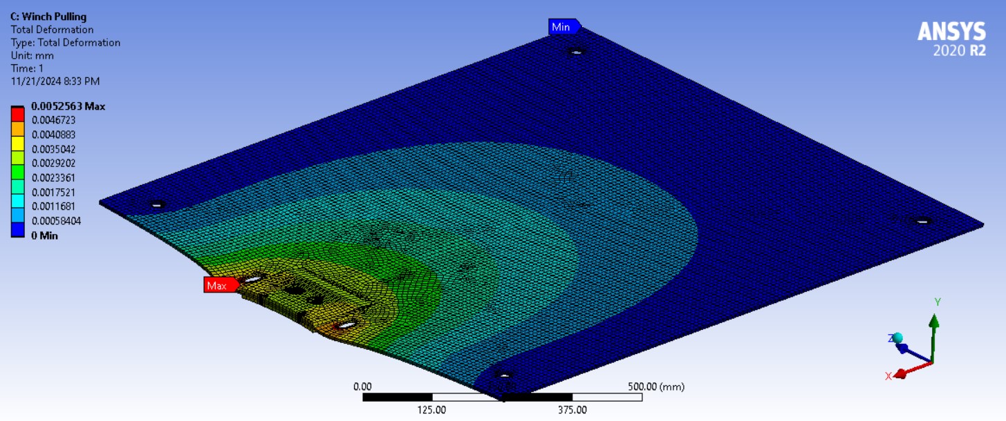
Total deformation FEA results of winch pulling slider – Click to Enlarge
The total deformation FEA result shows a maximum deformation of 0.005 mm, indicating that the steel slider plate experiences minimal displacement under the applied winch pulling force and remains structurally stable during extraction.
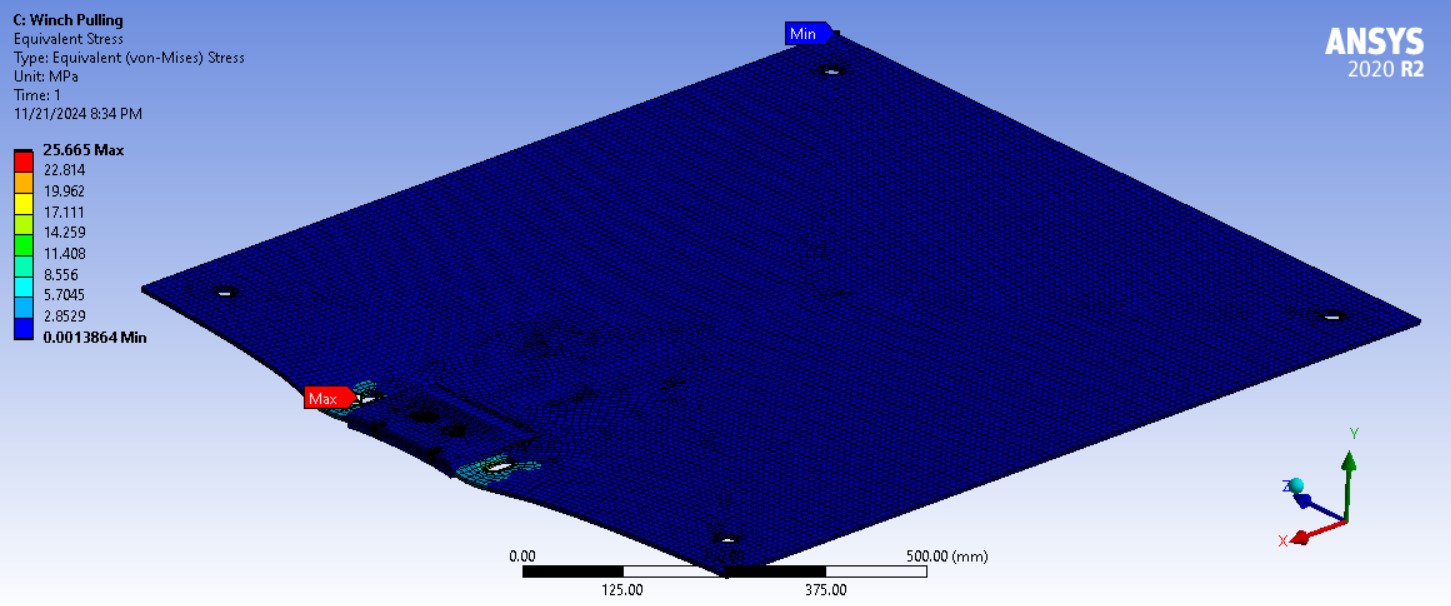
Equivalent (von-Mises) stress FEA results of winch pulling slider – Click to Enlarge
The maximum stress recorded on the steel slider plate was 25.665 MPa. Given the high strength of steel, this value is well within the material’s yield strength, confirming that the plate can handle the applied forces without reaching its failure limits or experiencing any material yield.
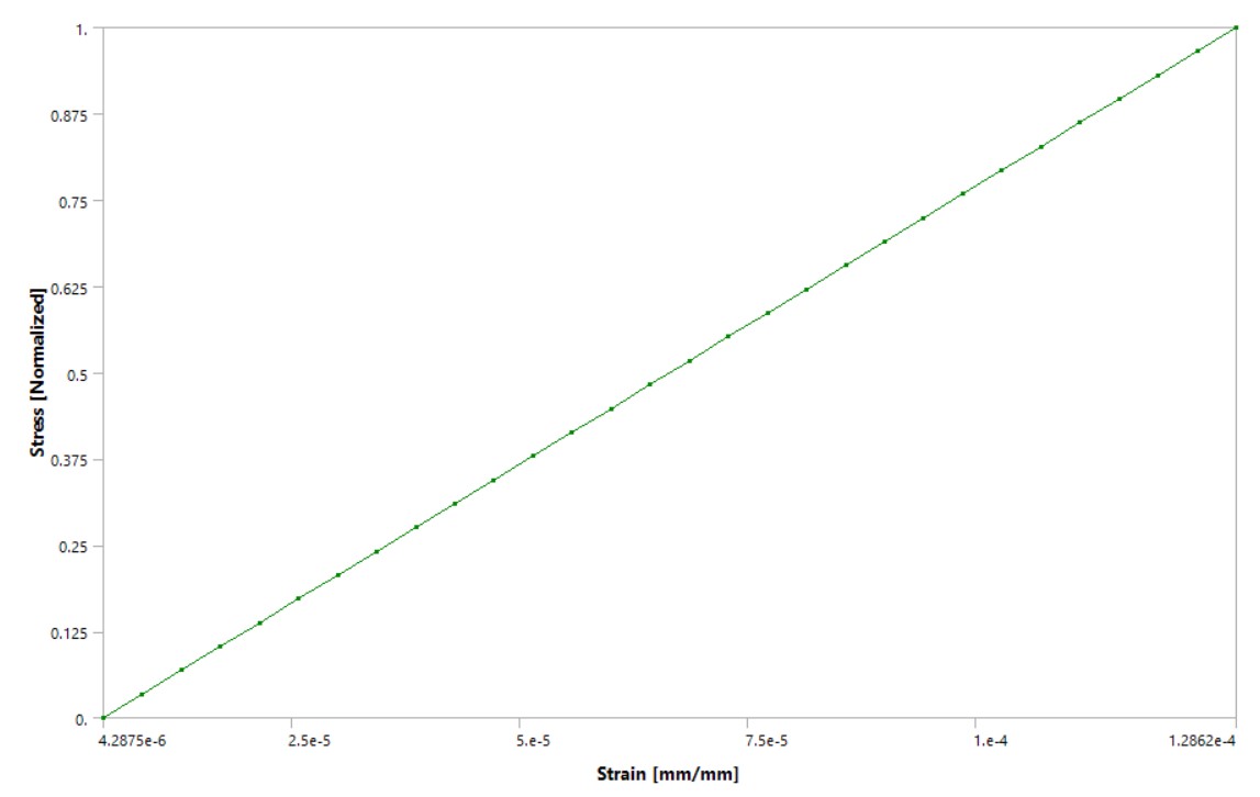
Stress-strain curve of winch pulling FEA – Click to Enlarge
The stress-strain analysis demonstrated that the steel slider plate remains within its elastic limit under the applied load. This ensures that the plate will not experience permanent deformation and will return to its original shape once the force is removed, maintaining its integrity and long-term durability.
These FEA results collectively validate the design and the use of steel as the material for the slider plate, confirming its adequacy and reliability for the intended application.
WINCH PULLING RESULTS SUMMARY
The analysis determined that the gravitational force acting on the slider plate due to the compost weight is 6,610.44 N, with a horizontal pulling force of 4,627.31 N required to overcome friction. This same force acts on the inner side of the hole where the hook is attached. Finite Element Analysis (FEA) revealed a maximum deformation of 0.005 mm and a maximum stress of 25.665 MPa, with the stress-strain curve indicating that the material remains within its elastic limit. These results confirm that the slider plate can withstand the applied forces without failure or permanent deformation, ensuring structural integrity.
Managing organic waste depends on maintaining optimal conditions that support worm activity and microbial decomposition. Key factors such as temperature, moisture, and the consistent addition of organic waste must be carefully managed to ensure efficient composting. Once worms are introduced into the system, waste will be added on an ongoing basis for processing.
This report outlines the ideal operating conditions for vermicompost.
VERMICULTURE STORAGE CHAMBER LOAD AND HANDLE STRESS EVALUATION
Section coming soon…
CHAMBER LOAD AND HANDLE FORCE FEA ANALYSIS AND RESULTS
This report analyzes the load on the chamber of the drawer and the force on the handle of the drawer. The drawer will be positioned right below the main chamber, and it will be pulled by the platform-pulley assembly parallel to the tension vector shown above. A CAD model of the drawer with its perforated bottom plate is shown below.
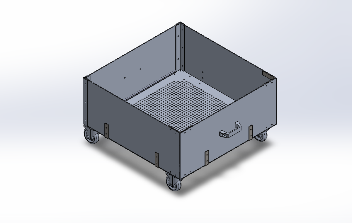
Drawer CAD – Click to Enlarge
Five primary simulations were conducted in ANSYS 2025 R2 Student Edition to validate the analytical results from the calculations. The first simulation shown in the figure below assessed the bottom plate under vermicompost weight. A uniform stress of 32.89 lb/ft² was applied across the plate, with all edges fixed to simulate attachment to the chamber frame. Structural steel was used with elastic modulus E = 200 GPa, Poisson’s ratio ν = 0.3, and yield strength σ_yield = 250 MPa. The objective was to evaluate total deformation under static loading. The ANSYS simulation revealed the deformation pattern across the entire bottom plate under the applied load. The following contour plot shows total deformation values ranging from zero at the fixed edges to maximum displacement at the plate center.
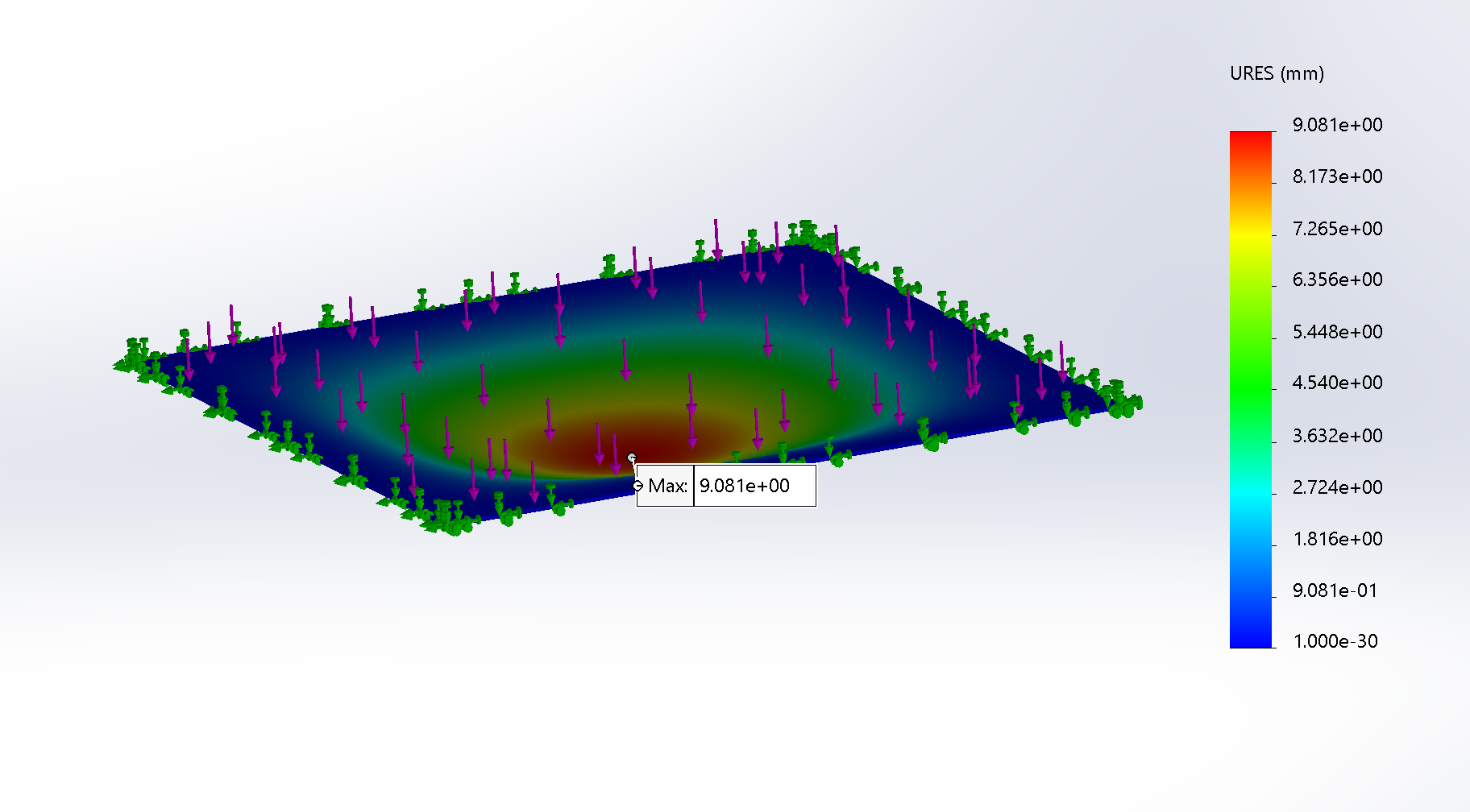
FEA Results for Slider – Total Deformation – Click to Enlarge
The FEA above resulted in a maximum deformation value of only 9.08 millimeters, which is highly trivial and ensures that the slider plate is structurally sound under a load of 1984.15 lbf.
Once the calculations were verified for the above FEA, a second simulation was conducted on the perforated bottom plate of the drawer. Since all the vermicompost held by the slider would drop onto the drawer, the same uniform stress of 32.89 lb/ft² from the vermicompost weight was applied to this perforated bottom plate.
Despite the perforations, the maximum deformation was only 0.77 millimeters (as shown by the FEA simulation below), ensuring that the drawer could withstand the same load experienced by the removable steel plate.
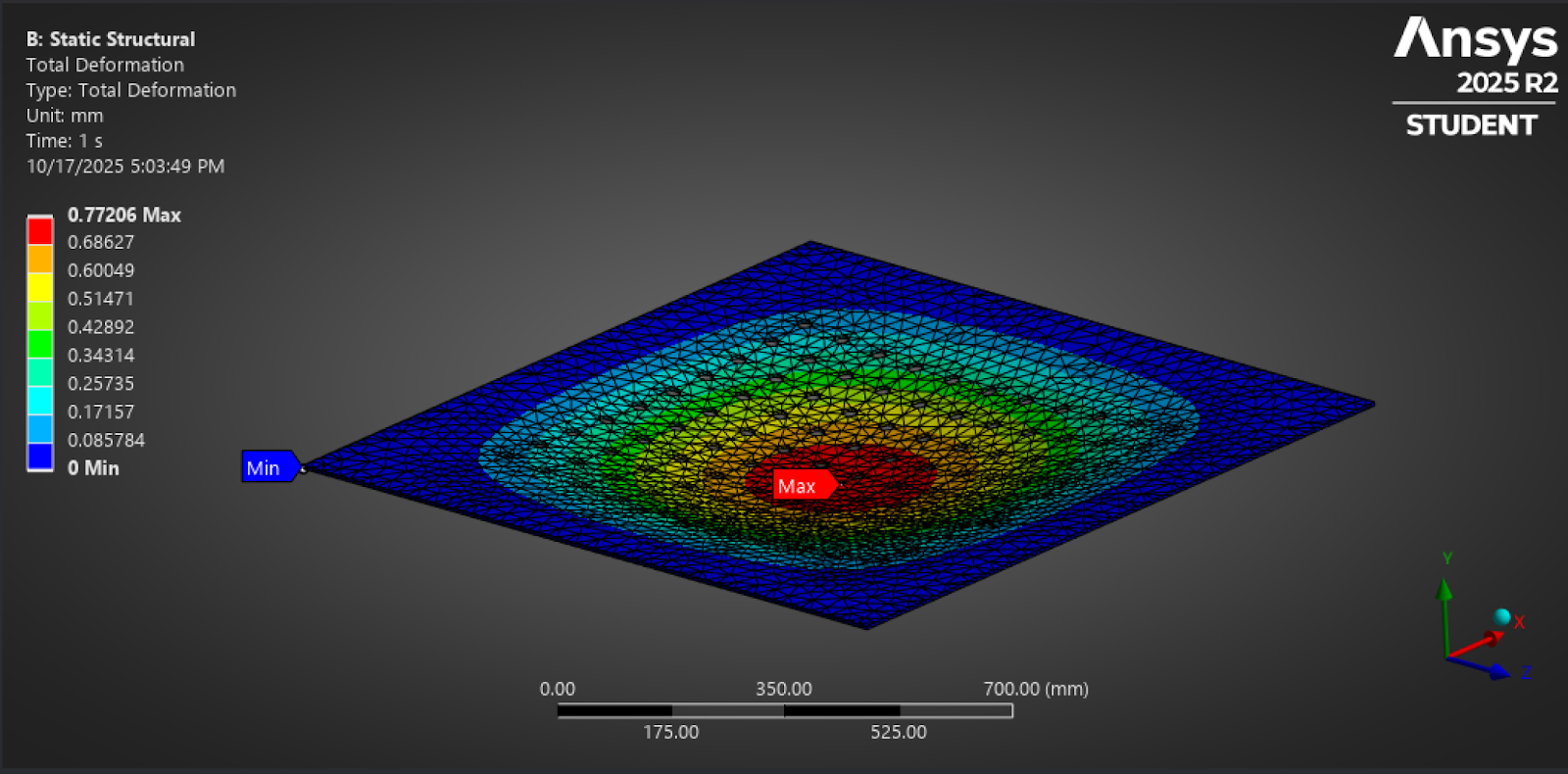
ANSYS Results for Drawer Bottom Plate – Total Deformation Contour – Click to Enlarge
After verifying the calculations, a third simulation was conducted on the drawer handle. This simulation evaluated the drawer handle and side plate assembly under winch extraction.
Referring to the “Calculations and FEA of Hammer Impact on Slider” section, the slider/separator plate is the component of the assembly that is responsible for retaining the waste and vermicompost before it reaches maximum capacity and needs to be loaded onto the drawer. This slider/separator is hammered into the main structure manually, as shown by the linked graphic. Once it reaches maximum capacity, the slider is pulled out using the manual winch attached to the separator insertion platform. The winch used to extract the slider is the same winch used to extract the drawer. This extraction of the drawer is shown in the animation below.
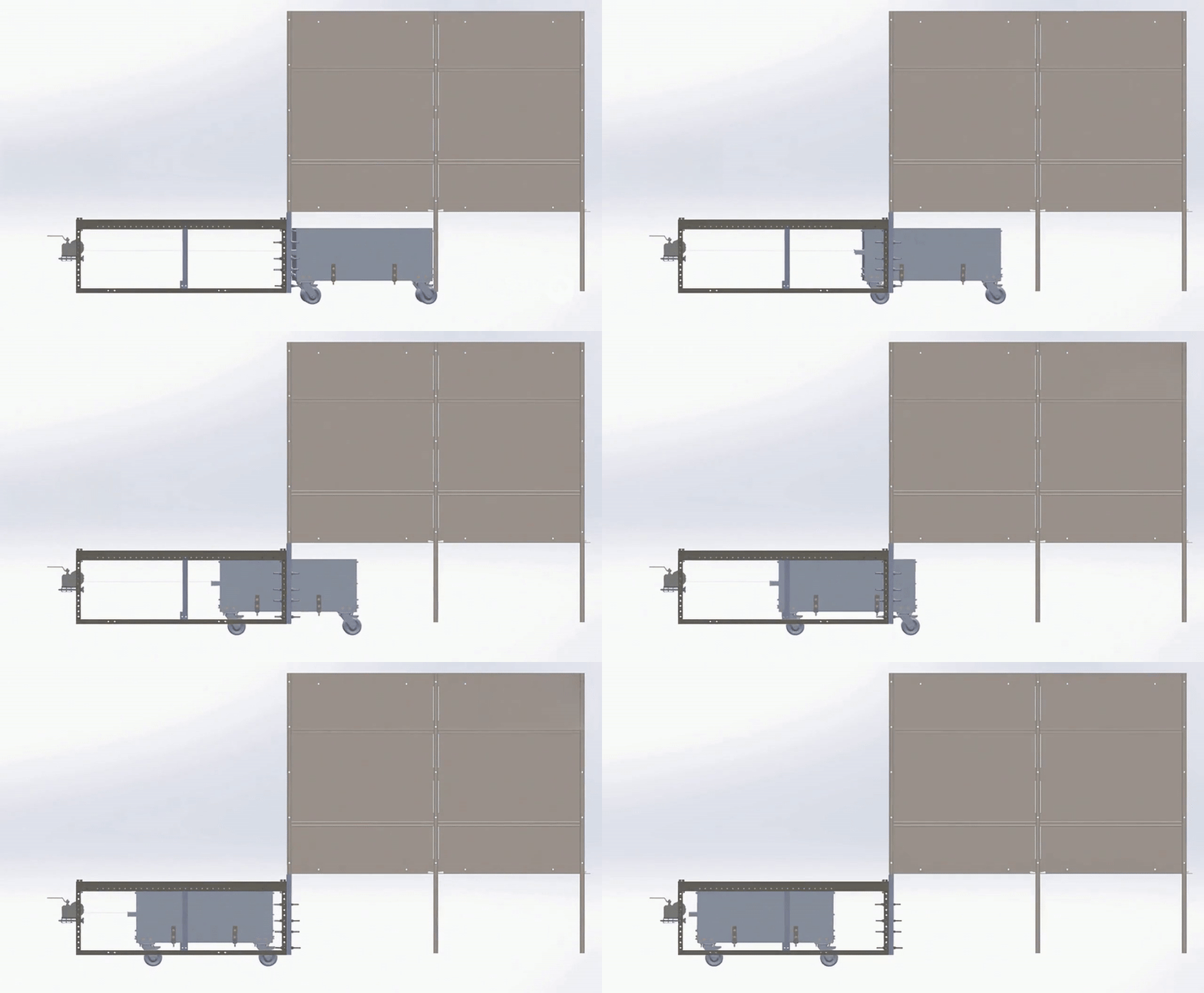
Animation of Winch Pulling Drawer – Click to Enlarge
The winch was operated manually by a human rotating the winch handle (not shown), and a rope was tied to the handle and wrapped around the winch axle. Assume that a heavy-duty rope was used and that the working load limit of the rope was not reached throughout the motion. After the drawer is pulled out and dumped using the dumping mechanism, it is rolled back under the main structure, and the slider plate is pounded back into place manually using a hammer, ready to undergo the vermicomposting process again.
The required pulling force of 563.63 lbf was applied to the handle, with bolted joints modeled as fixed supports. The bolted joints shown in the FEA model represent the L-brackets (not shown) that are fixed in the same bolt locations to hold the drawer assembly together. The same structural steel used for the slider was used for the drawer plate, and SAE Grade 5 properties were assigned to bolts and nuts that were mounted on the plate using L-brackets. The goal was to determine the factor of safety and check for localized stress failure. ANSYS simulations were performed to reflect the minimum factor of safety and maximum deformation, respectively, for the handle and side plate under loads.
The image below shows the resulting safety factor plot of the assembly.
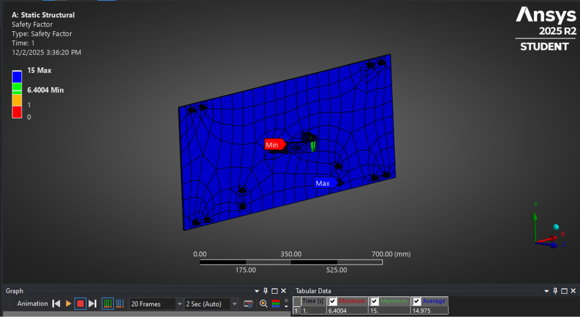
ANSYS Plot for Safety Factor – Handle and Side Plate Assembly – Click to Enlarge
As shown by the above plot, the minimum factor of safety was 6.4004, occurring at the joined section of the handle. This factor of safety is well above the minimum required factor of safety of 2. This high value indicates that the assembly is structurally viable and can handle the stress exerted by the pulling force.
An additional plot was produced depicting the total deformation of the handle and drawer wall assembly. As shown below, the maximum deformation is only about 0.046 millimeters, which is highly insignificant and can be assumed negligible.
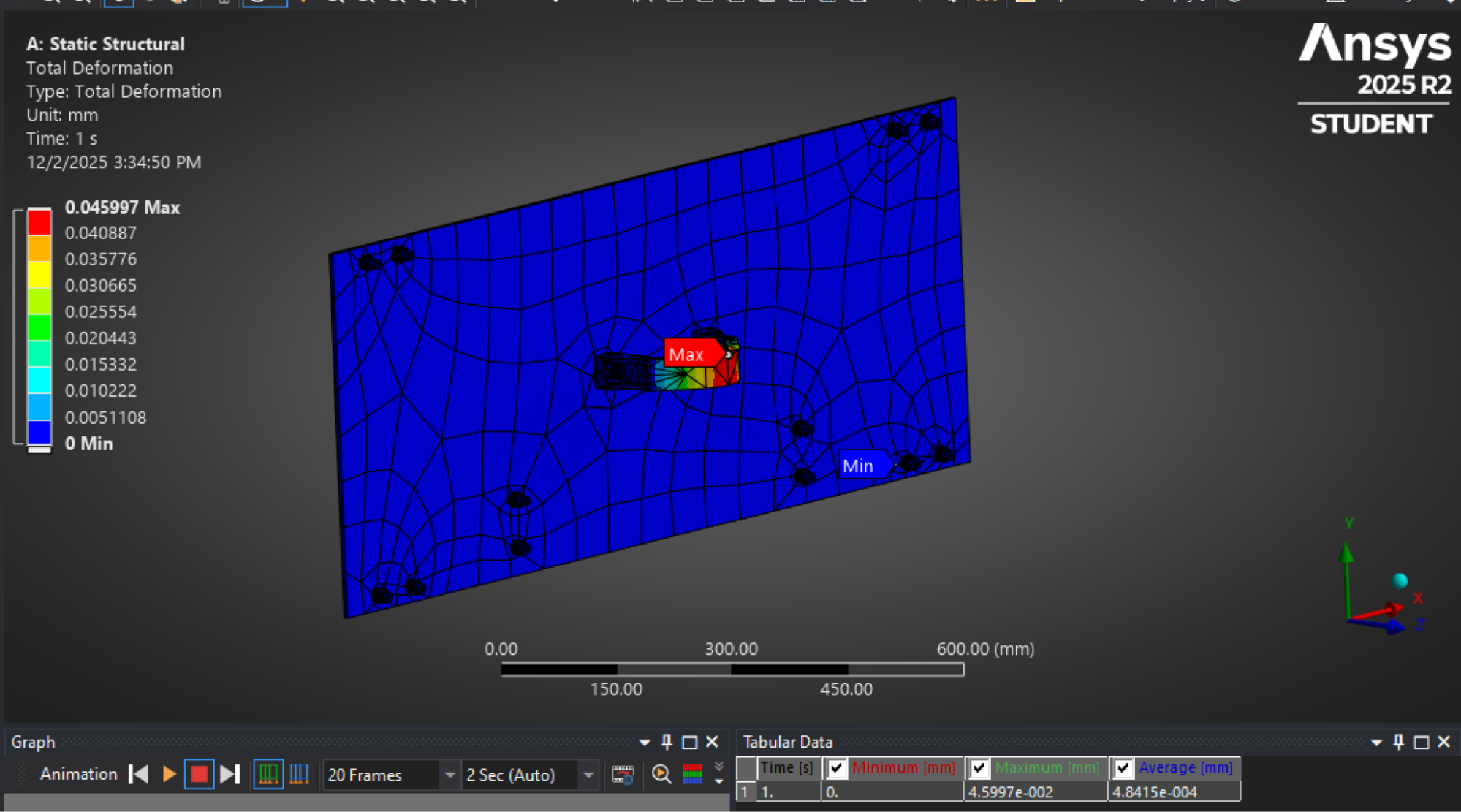
ANSYS Plot for Handle Deformation – Localized Displacement – Click to Enlarge
Additionally, another FEA was conducted to see if the winch could handle the pulling force (tension “T” from here) of 563.63 lbf. However, due to the lack of adequate cores available in the ANSYS Student Edition, the simulation was performed at what was assumed to be the critical failure points of the winch-and-struts assembly: the bolts used to attach the winch assembly to the struts.
The winch is secured by four bolts, so the total pulling force was divided equally, resulting in a shear force of 563.63 / 4 = 140.9075 lbf applied to a single bolt. A single SAE Grade 5 bolt was modeled under this shear load, with one end fixed and the shear force applied perpendicular to the bolt axis at the opposite end.
As shown in the factor of safety (FoS) plot below, the minimum FoS for the single bolt under shear was 0.40. Although the factor of safety is lower than the required minimum FoS of 2.5, this FoS only represents a localized condition where one bolt is handling the force that all four bolts would be handling in a real-life scenario. Since four bolts share the total 563.63 lbf pulling force load, the effective system-level safety margin is significantly higher. In other words, since the FoS of 0.4 is only considering one bolt, the true FoS will be much higher (closer to the required number of 2) once four bolts are in place. No yielding or excessive deformation was observed within operational limits.
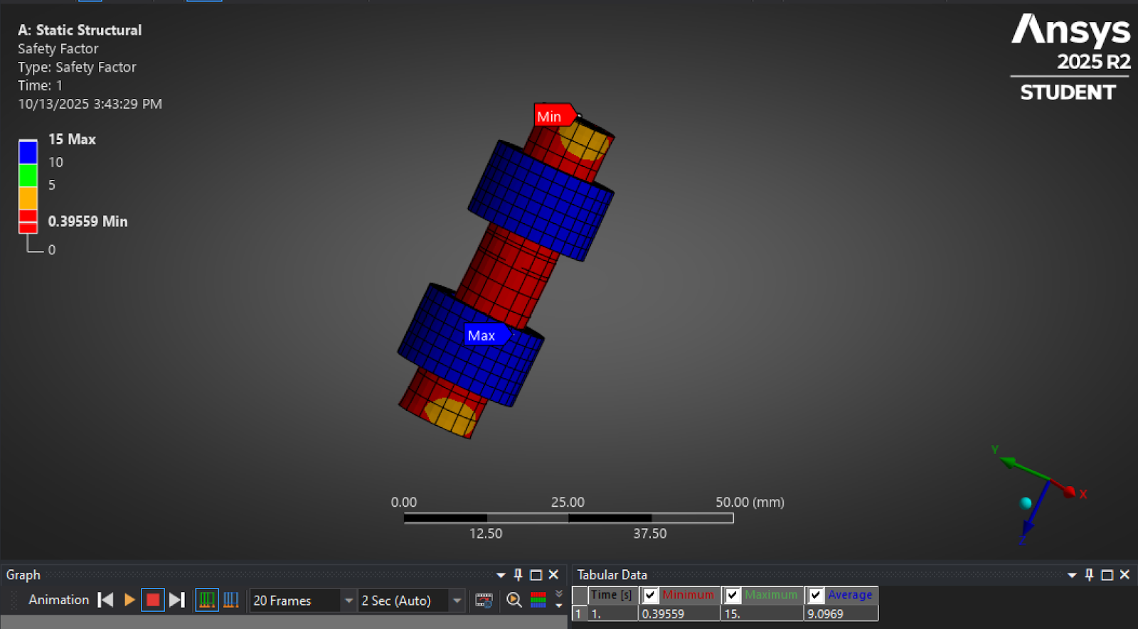
ANSYS Plot for Safety Factor – Single Bolt Under Shear – Click to Enlarge
In the next figure, the ANSYS deformation plot showed a maximum deformation of 0.05 mm. This deformation value, which is similar to that shown by the displacement plot for the handle deformation, is insignificant and can be assumed negligible.
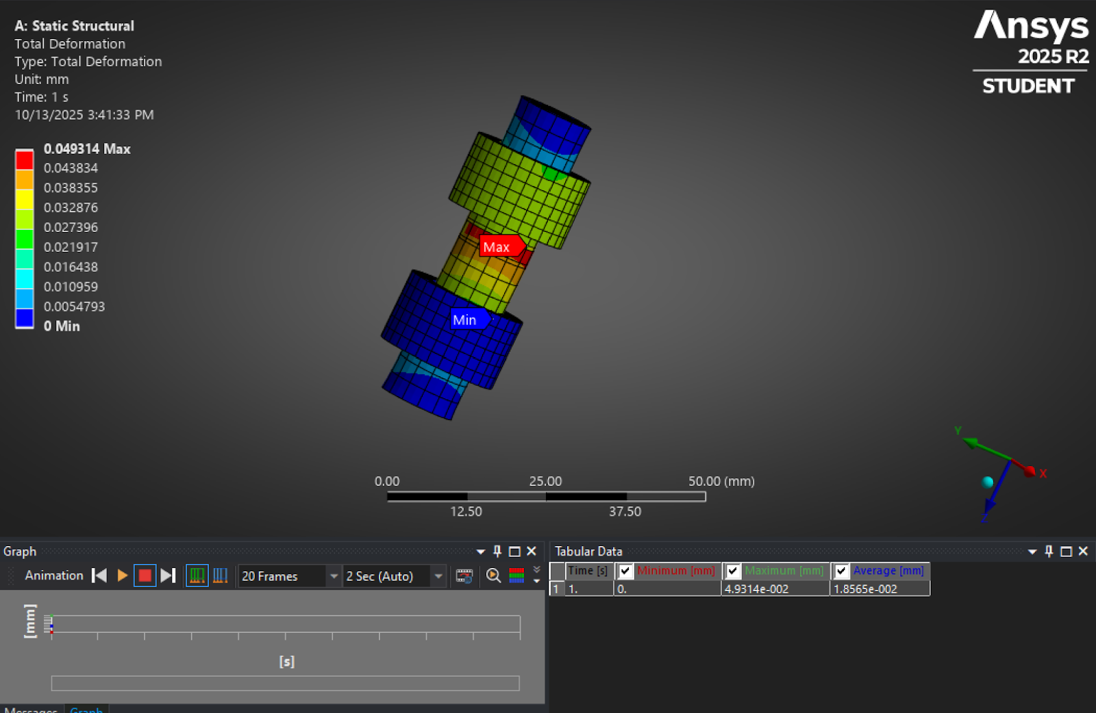
ANSYS Plot for Total Deformation of Bolt – Click to Enlarge
An additional point of failure that was addressed in the FEA was the shear on the winch gears and shaft due to the tension “T” caused by the cable. The FEA was conducted applying the pulling force of 563.63 lbs to the center of the shaft. As shown in the figure below, the FEA showed a minimum factor of safety of 1.171 at one of the endpoints of the shaft.
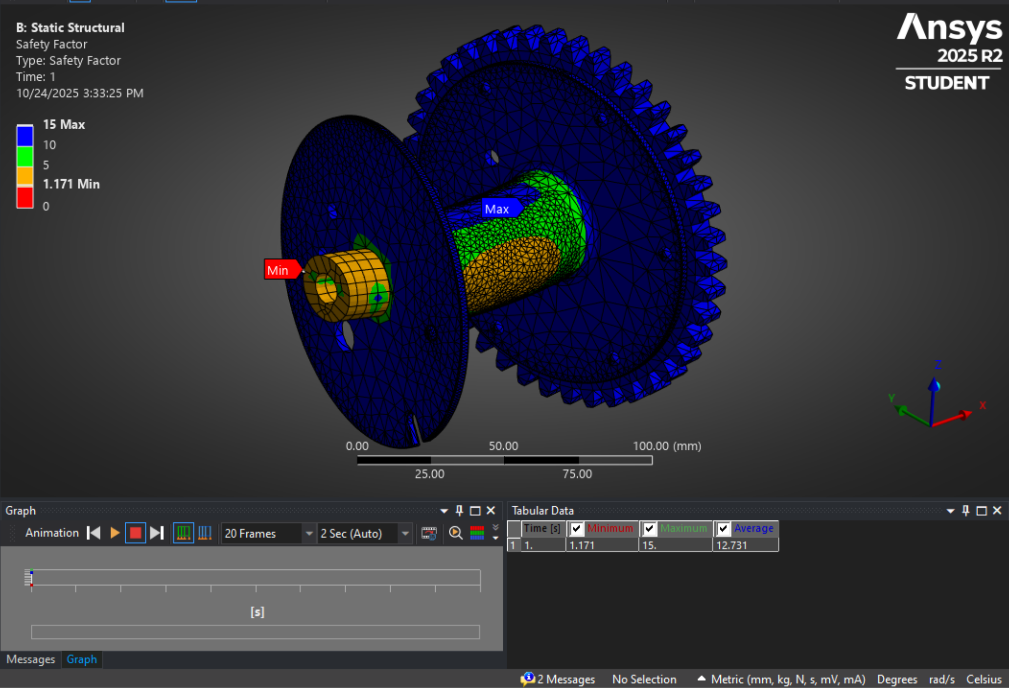
ANSYS Plot for Safety Factor – Cable Force on Winch Shaft – Click to Enlarge
Since only components were analyzed and only the critical points were checked for failure, a full analysis must be performed before construction of the separator platform to verify that the platform can withstand the loads well above the minimum required factor of safety of 2.
CHAMBER LOAD AND HANDLE FORCE RESULTS SUMMARY
Under a 1,984.15-pound-force quadrant load, the bottom plate exhibited a maximum total deformation of 0.772 millimeters, concentrated at the center of the plate, with minimal displacement at the fixed boundaries. This small deflection confirms that the 6.35-millimeter steel plate thickness is structurally adequate and that the design operates well within the elastic limit of the material. No plastic deformation or stress concentrations were observed. Since the slider plate does not have any perforations like the drawer’s bottom plate, it can be assumed that the slider’s dimensions are also structurally adequate and that its design also operates well within the steel’s elastic limit.
The drawer handle simulation, subjected to a 600-pound-force pulling load, showed a minimum factor of safety of 6.4004 and maximum deformation of 0.046 millimeters. The FoS contour indicated that all regions of the handle and its bolted supports remained well below the material’s yield limit. The area around the handle experienced the highest stress, but with an FoS > 6, this remained within safe limits for repeated use.
Comparison of analytical and FEA results confirmed consistency: quadrant load (1984.15 pound-force vs. 2,000 pound-force conservative), maximum deflection (<1 millimeter estimated vs. 0.772 millimeter), winch pull force (563.63 pound-force vs. 600 pound-force modeled), and factor of safety (>3 assumed vs. 6.4). Both methods verified that the chamber’s current design and material selection are structurally sound.
The bolt shear simulation under 140.9075 lbf revealed a minimum factor of safety of 0.39559 and a maximum total deformation of 0.049314 mm. The lowest safety factor occurred at the shear plane near the fixed support, while maximum deformation was observed at the loaded end. Although the factor of safety of 0.40 appears low for a single bolt, this represents the worst-case localized condition, considering that the three other bolts have failed and only one bolt is handling all the pulling force. Since four bolts share the total 563.63 lbf pulling force load, the effective system-level safety margin is significantly higher. No yielding or excessive deformation was observed within operational limits.
Furthermore, the Factor of Safety (FoS) plot shown in the figure for cable force on the winch shaft depicts a critical point of failure in the winch gears. However, although the desirable FoS when considering the ultimate strength of the material used needs to be at least 2.5, the low FoS of 1.171 occurs at a point that is supported by a bolt that counteracts the shear at that point. Therefore, the shear at that point can be considered negligible.
The FEA simulations confirm that the vermicompost storage chamber and drawer handle assembly are structurally adequate to withstand their respective load conditions. The bottom plate experiences negligible deflection (0.77 mm), and the winch mounting bolts maintain structural integrity under distributed shear (563.63 lbf total across four bolts). No design modifications are required for the current geometry or material. However, it is recommended that during fabrication, proper weld continuity, bolt pre-tension, and use of SAE Grade 5 or higher fasteners be ensured to maintain integrity under long-term cyclic loading. These findings verify prior calculations and demonstrate that the structure is safe, efficient, and ready for implementation.
Interpretation:
- The current bolt arrangement and plate geometry are sufficient to withstand the operational pulling force.
- No yielding or excessive stress concentration was observed at the handle interface.
- Deformation is negligible (0.046 mm) on the handle-winch contact point.
VENTILATION SYSTEM DESIGN FOR VERMICOMPOSTING ECO-TOILET SPACE
Section coming soon…
VERMICULTURE ECO-TOILET REPLICATION DETAILS
 This section will be developed to include everything needed for replication and maintenance of the complete Vermiculture Eco-toilet Structure. Our goal is to simplify the process as much as possible by providing complete and easy to follow parts lists, cost analysis details, diagrams, assembly instructions and more. Wherever possible, we’ll also provide all information in the form of web tutorials, PDF and file downloads, as well as video tutorials.
Click the following links to jump directly to the related sections:
PARTS LIST
This section will list all the parts for replication of the complete Vermiculture Toilet unit. We will add these details once we’ve finished the updated design.
COST ANALYSIS
This section will list our initial cost projections for replication of the complete Vermiculture Toilet unit and then be updated with actual costs once we have purchased and assembled our first unit. We’ll also include here the best materials sources once we’ve identified them.
DIAGRAMS
Design 2 for this structure is well on its way but we need help finishing it. Click HERE if you’d like to apply to join our all-volunteer team and help us complete these designs.
ASSEMBLY INSTRUCTIONS
Once they are done, we’ll add here all the final assembly instructions for the Vermiculture Toilet. We’ll then update them once we construct our first one and keep adding here any additional bed designs and/or modifications we come up with.
ASSEMBLY VIDEOS
VIDEOS COMING TO COVER ALL ASPECTS OF THE VERMICULTURE TOILET ASSEMBLY, TESTING, AND MAINTENANCE PROCESS – THESE HOW-TO INSTRUCTIONAL VIDEOS WILL PROVIDE STEP-BY-STEP INSTRUCTIONS FOR ALL ASPECTS OF REPLICATION AND OPERATION OF THESE STRUCTURES
SEE OUR HOW TO HELP AND/OR CROWDFUNDING CAMPAIGN PAGE TO HELP CREATE ALL THE TUTORIAL VIDEOS FASTER
CONSTRUCTION RELATED DOWNLOADS
Once they are done, we’ll add here download links for all the final AutoCAD, SolidWorks, and other files for the Vermiculture Toilet.
OPERATION AND MAINTENANCE
This section will include complete troubleshooting plans, maintenance schedules and plans, and all other details related to the long-term care of your Vermiculture Toilet. These details, though, must wait until we’ve got the experience with our own units to share. Please bookmark this page and check back later. If you’d like to follow our progress, subscribe to our weekly updates blog: https://onecommunityglobal.org/one-community-blog/
VERMICULTURE OPERATING CONDITIONS & SCHEDULE
 Vermiculture, or worm composting, is a sustainable and highly effective method of managing organic waste. It depends on maintaining optimal conditions that support worm activity and microbial decomposition. Key factors such as temperature, moisture, and the consistent addition of organic waste must be carefully managed to ensure efficient composting. Once worms are introduced into the system, waste will be added on an ongoing basis for processing.
This report outlines the ideal operating conditions for vermicomposting waste generated from vermiculture toilets in the Earthbag Village. It also examines the effects of temperature extremes on system performance and offers practical strategies for maintaining balance during periods of both high and low temperatures.
In this report, various parameters that need to be carefully managed throughout the year are discussed to ensure smooth operations in varying seasonal conditions. Additionally, the optimum emptying schedule is covered, which is essential to maximize the system’s potential and maintain efficiency, preventing overloading or imbalance that could hinder composting. By adhering to these guidelines, vermicomposting can thrive year-round, producing nutrient-rich compost while minimizing disruptions.
IDEAL TEMPERATURE RANGE
Maintaining the right temperature is essential for a healthy and efficient vermicomposting system. Worms thrive within a specific range, ensuring optimal activity and reproduction, while extreme temperatures can slow the process or be harmful. Below are the key temperature thresholds for their survival and performance.
Optimal Range: 55°F to 85°F (13°C to 29°C)
- Worms are most active and reproduce efficiently in this range.
- The composting process is faster, and microbial activity supports the worms.
Lower Threshold: 40°F (4°C)
- Worms enter a state of dormancy when temperatures drop too low.
- Below this, they may die or become less effective in waste processing.
Upper Threshold: 95°F (35°C)
- Worms start to die or become stressed when exposed to excessive heat.
- High temperatures also dry out the bedding, disrupting the system.
Below this range, the ecosystem operates at reduced efficiency, while temperatures above 35°C (95°F) can prove fatal to the worms. It is important to note that this temperature refers to the compost within the processing chamber, not the ambient room temperature. If the chamber is placed in a room at 95°F, the worms will instinctively migrate to cooler areas within the compost. As long as the core temperature of the compost remains within safe limits, whether in hot or cold conditions, the worms will continue to function effectively.
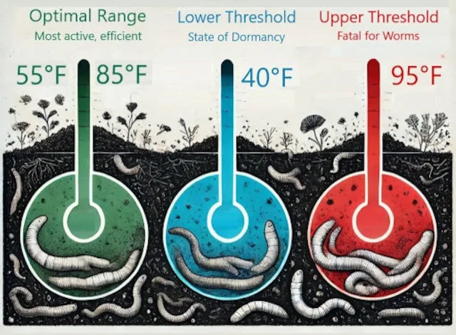
FACTORS AFFECTING TEMPERATURE
Several factors influence the temperature within a vermicomposting system, impacting worm activity and overall efficiency. Understanding these elements helps in maintaining a stable environment for optimal composting. Below are key factors that regulate temperature.
External Climate:
- Outdoor systems are more susceptible to seasonal temperature changes.
- Insulation and shading are necessary in extreme climates.
System Size:
- Larger systems generate more internal heat due to microbial activity.
- Overheating can occur in smaller systems if waste is added excessively.
Bedding Material:
- Materials like straw or hay, leaves, grasses, and wood shavings retain moisture and regulate temperature.
- Avoid dense materials that trap excessive heat.
Aeration:
- Proper airflow helps dissipate heat and maintain aerobic conditions.
- Stagnant systems can overheat and produce foul odors.
VERMICOMPOSTING IN HIGH TEMPERATURES (SUMMER)
 In extreme heat, worms struggle to thrive, and bacteria take over decomposition. This process consumes excessive oxygen, creating an unsuitable environment for worms. High temperatures also soften or liquefy organic material, attracting pests like midges and disrupting the system. Managing heat is crucial to maintain balance and ensure effective composting. In this section, we discuss the effects of high temperatures on vermiculture, steps to ensure smooth operation, and emergency measures to be taken during the summer.
IMPACT OF HIGH TEMPERATURES ON VERMICOMPOSTING
Extreme heat disrupts vermicomposting, stressing worms and accelerating microbial activity. This depletes oxygen and creates unfavorable conditions. Below are the key challenges caused by high temperatures.
Worm Stress and Mortality:
- Stress: Temperatures above 85°F (29°C) cause worms to become less active, reducing their ability to process waste effectively.
- Mortality: At temperatures exceeding 95°F (35°C), worms may die from heat stress.
Reduced Reproductive Rates:
- Worms reproduce less efficiently in high temperatures, potentially leading to a declining population over time.
Increased Microbial Activity:
- Elevated temperatures can accelerate microbial decomposition, generating more heat and further raising the system’s temperature, creating a positive feedback loop that can lead to overheating.
Moisture Loss:
- Higher temperatures increase evaporation, drying out the bedding and creating an unsuitable environment for worms.
Odor Problems:
- Excessive microbial activity in anaerobic conditions can result in foul odors, especially if waste decomposes too quickly.
Pest Infestation:
- High temperatures may attract unwanted pests, such as flies, which can disturb the system’s balance.
STEPS TO MAINTAIN SMOOTH OPERATIONS IN HIGH TEMPERATURES
Managing vermiculture compounds in high temperatures requires careful attention to ensure worms remain healthy and maximally effective in processing waste. High heat can stress worms, accelerate microbial activity, and disrupt the system’s balance. Implementing proper cooling techniques, maintaining moisture levels, and regulating waste input are essential to preserving an optimal environment for composting during hot weather.
CONTROL HEAT GENERATION
Managing heat generation is vital for maintaining a balanced vermiculture system, particularly in warm conditions. This ensures that the worms and microbial activity thrive without overheating the environment. One way to achieve this in smaller systems is by:
- Moderate Waste Input: During high heat, avoid overloading the system with waste, as excessive organic material generates heat during decomposition.
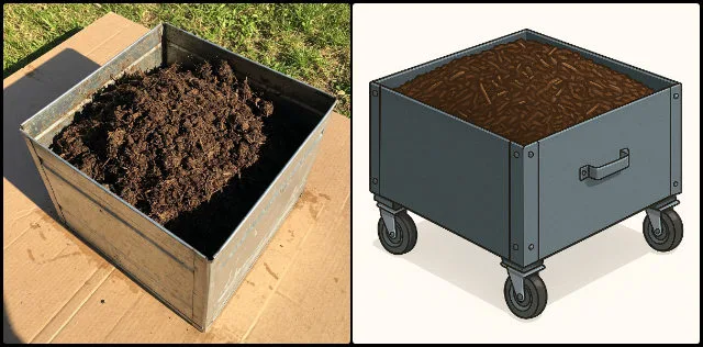
Our indoor vermiculture system is strategically positioned below ground level, which naturally helps regulate temperature by staying cooler during the summer months. The shaded roof above adds an additional layer of insulation, while the enclosed design of the compost chamber protects the system from high external temperatures, with an added ventilation system keeping the temperatures in check. The thermal mass of the surrounding earth further contributes to stable internal conditions, minimizing fluctuations caused by seasonal changes.
To initiate the system, we first lay a foundation of up to six inches of soil or damp bedding materials, such as shredded cardboard or wood shavings. This is followed by a layer of organic waste, after which we introduce the worms to activate the composting process. Human waste is added only after the worms have been established, allowing them to adapt and begin breaking down the initial materials.
At this stage, given the large size of our system, the system becomes largely self-regulating but would require monitoring to maintain optimal operating conditions. As composting progresses, a dense, well-insulated layer of decomposed material forms. This not only helps maintain internal temperatures but also serves to buffer any heat generated during microbial activity. The more compost accumulates, the more effectively it can absorb and regulate heat, unless the system needs to be emptied after a period of about six months.
While active monitoring is facilitated by temperature and RH sensors, which do not require human intervention, periodic check-ins are beneficial to ensure the system remains balanced and waste input is appropriate. In addition, bedding materials such as dried grass and wood shavings can be incorporated to improve aeration, manage moisture, and further regulate heat buildup within the composting chamber.
Here’s a video of the complete process of managing heat issues for our vermiculture system:
VIDEO COMING: HEAT CONTROL STRATEGIES FOR VERMICULTURE SYSTEMS IN SUMMER
SEE OUR HOW TO HELP AND/OR CROWDFUNDING CAMPAIGN PAGE TO HELP CREATE ALL THE TUTORIAL VIDEOS FASTER
ENHANCE VENTILATION
Proper ventilation is key to maintaining an optimal environment for worm activity and preventing overheating. By ensuring adequate airflow, you can support aerobic conditions and regulate temperature effectively. Ways to achieve this in traditional smaller systems are as follows:
- Aerate the System: Use a tool to turn/mix the bedding periodically to allow heat to dissipate and ensure proper oxygen flow.
- Add Ventilation Pipes: Install perforated pipes or mesh covers to improve airflow and reduce heat buildup in case of emergency.
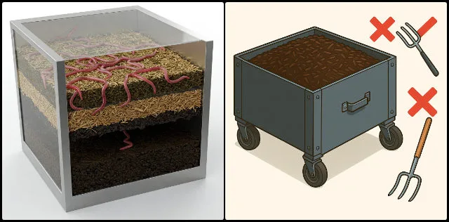
Our vermiculture system operates with minimal disruption to the bedding once the worms are introduced, remaining undisturbed until the drawers are emptied. Aeration through mixing tools is not feasible and must be avoided to prevent harm to the worms. The worms, consisting of earthworms and red wigglers, naturally create ventilation within the compost. Earthworms burrow to the bottom, decomposing material, while red wigglers stay near the surface. Additionally, dry materials like grass or wood shavings are added to prevent compaction, help with aeration, and maintain a proper carbon-to-nitrogen balance. This layering technique supports a healthy environment for the worms and encourages efficient composting.
The system also incorporates an active ventilation system that draws air from the top to regulate temperature and control odors. As organic waste is added at the top and processed material is removed from the bottom, the worms continue their work in the middle and upper layer. The gradual breakdown of compost fills the drawers during the initial period itself, emptied after six months to ensure complete breakdown into compost and enough time for worms to relocate, minimizing the need for active aeration. The added dry materials further assist in maintaining moisture levels, preventing the system from becoming too wet. This approach ensures a balanced, self-sustaining composting environment with minimal intervention.
Here’s a video about enhancing ventilation in our vermiculture system:
VIDEO COMING: ENHANCING VENTILATION IN VERMICULTURE SYSTEM
SEE OUR HOW TO HELP AND/OR CROWDFUNDING CAMPAIGN PAGE TO HELP CREATE ALL THE TUTORIAL VIDEOS FASTER
MAINTAIN MOISTURE LEVELS
Maintaining the right moisture levels is essential for the health of both the worms and microbial activity in the system. Adequate moisture helps regulate temperature, supports the composting process, and prevents the bedding and compost from becoming too dry or having higher moisture levels. Ways to achieve this in a smaller system are as follows:
- Regular Spraying: Use spray bottles to mist the bedding with water to maintain humidity and help cool the system.
- Add Moist Bedding: Introduce dampened materials like straw or hay, leaves, grasses, and wood shavings to regulate both moisture and temperature.
- Remove Excess Moisture: If the compost mix contains too much liquid, it should be drained to maintain the ideal moisture level for healthy composting.
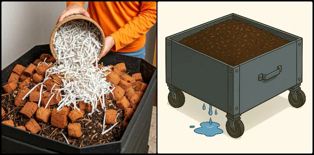
In our vermiculture system, moisture levels tend to be high because of the nature of human waste. The perforated bottoms of the drawers help manage this by allowing any excess liquid to drain out, which prevents the compost from becoming too wet. The 1-foot layer of bedding material at the bottom of the drawer holds enough moisture to keep the environment healthy for the worms.
Since waste is added regularly, there is a steady input of moisture, even though we use a urine-separating toilet. As the liquid moves through the compost mix, any extra liquid filters down through the bedding and drains out at the bottom, keeping the system balanced.
Additionally, as discussed earlier, the layering technique prevents compaction and includes dry materials like grass or wood shavings. This helps balance the compost by keeping carbon levels high and maintaining the proper nitrogen ratio, so no extra moisture is usually needed. However, in rare cases where additional moisture is required, it can be added using a water spray, but only when absolutely necessary. Wet bedding should only be introduced if temperatures rise above 80°F. That said, since the system is housed in an enclosed, below-ground chamber, it is unlikely that temperatures will get that high. With close monitoring in place, any moisture adjustments will only be made under extreme conditions.
Here’s a video about maintaining moisture levels in our vermiculture system in summer:
VIDEO COMING: MOISTURE CONTROL FOR VERMICULTURE SYSTEMS IN SUMMER
SEE OUR HOW TO HELP AND/OR CROWDFUNDING CAMPAIGN PAGE TO HELP CREATE ALL THE TUTORIAL VIDEOS FASTER
CHOOSE WORM SPECIES
Choosing the right worm species is essential for maintaining a healthy vermiculture system, especially during the summer when temperatures can become extreme. Some worms are better suited for warmer climates, ensuring better performance and composting efficiency.
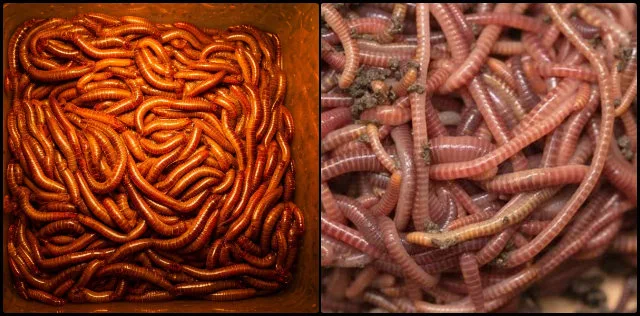
African Nightcrawlers Red Wigglers
In our system, both African Nightcrawlers and Red Wigglers will be used because they each perform well in different parts of the compost and help improve the overall composting process. African Nightcrawlers prefer the deeper, warmer areas at the bottom of the processing chamber, where they can handle large amounts of organic material. Red Wigglers, on the other hand, thrive in the cooler, shallow top layers and are effective at breaking down finer waste.
This combination helps maximize the composting process. The Red Wigglers work at the surface where the compost tends to heat up more, but the heat is quickly released due to the large surface area and the exhaust system. The ventilation setup helps regulate temperature by pulling air down from the toilet seats, creating airflow that cools the top layer of compost and removes odors. Meanwhile, the heat from composting activity in the lowest layers is released more slowly, creating a warmer environment where the African Nightcrawlers can thrive. Together, these worms keep the system efficient and produce rich, healthy compost.
MONITOR AND ADJUST
Regular monitoring and timely adjustments are key to maintaining a healthy vermiculture system, particularly in fluctuating temperatures. Keeping track of the system’s conditions ensures worms and microbes remain active and healthy. In traditional smaller systems, the following are used:
- Temperature Monitoring: Use a thermometer to measure the system’s internal temperature daily or at regular intervals to monitor for optimum temperature.
- Waste Management: Adjust the amount of waste input based on the system’s temperature to avoid overheating.
In our system, we plan to install a temperature sensor to actively monitor the entire room where the system is located, allowing us to manage and adjust the temperature as needed. Additionally, infrared thermometers will be used to check the temperature of the processing chamber. If the temperature needs to be lowered, we may adjust the addition of nitrogen- or carbon-rich compounds to reduce anaerobic activity. In the worst-case scenario, wet bedding material or water from the top can be added to help regulate the temperature, as previously discussed. However, this is unlikely to be necessary, as the constant addition of human waste that contains moisture and carbon content naturally moistens the system with fluids and balances out the nitrogen.
We will be testing our temperature monitoring setup under warm conditions to evaluate sensor accuracy, control response, and the effectiveness of cooling strategies. Data collected will guide adjustments to ensure the system remains stable and prevents overheating during high ambient temperatures.
Here’s a video about monitoring and adjusting our vermiculture system:
VIDEO COMING: VERMICULTURE SYSTEM MONITORING & ADJUSTMENTS IN SUMMER
SEE OUR HOW TO HELP AND/OR CROWDFUNDING CAMPAIGN PAGE TO HELP CREATE ALL THE TUTORIAL VIDEOS FASTER
EMERGENCY MEASURES IN HIGH TEMPERATURE
If temperatures rise dangerously, immediate action is needed to protect the worms and stabilize the system. Below are key steps to prevent overheating and ensure their survival.
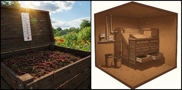
In case of traditional smaller systems, if the system overheats:
- Remove excess waste to lower microbial activity.
- Add fresh, damp bedding material to cool the environment.
- Remove and relocate the worms temporarily to a cooler area until the primary vermiculture compound stabilizes.
In our system, removing excess waste will not be feasible, so the ratios of waste input will be controlled, as discussed earlier. Wet bedding, such as soaked grass, can be added into the processing chambers from the top for summer use, but this will not be necessary since moist waste is added on a regular basis. Additionally, because the system is located below ground level, it is highly unlikely that the temperature would reach 80°F. The thick walls provide enough insulation from external temperature fluctuations, helping the chamber temperature remain within the optimal range. The exhaust and ventilation system also supports airflow, helping remove excess heat and maintain stable conditions.
However, if the temperature still exceeds 80°F, water may be added from the top to help regulate the temperature. This will only be done in rare situations, particularly in areas where temperatures are unusually high.
VERMICOMPOSTING IN LOW TEMPERATURES (WINTER)
 Low temperatures during winter can slow down or even halt the vermicomposting process by affecting the worms, microbial activity, and overall system functionality. It is crucial to understand these effects and implement strategies to maintain smooth operations during cold weather. In this section, we discuss the major challenges, steps to overcome them, and emergency measures to be taken during winter.
IMPACT OF LOW TEMPERATURES ON VERMICOMPOSTING
Cold weather can slow or halt the composting process by affecting worm activity and microbial decomposition. Understanding these challenges is key to maintaining efficiency during winter. Below are the major issues caused by low temperature:
Reduced Worm Activity:
- Dormancy: Below 50°F (10°C), worms become sluggish and less active, significantly slowing down waste processing.
- Hibernation: Prolonged exposure to temperatures near 40°F (4°C) may cause worms to enter a dormant state, halting reproduction and feeding.
Mortality:
- At temperatures below freezing, 32°F or 0°C, worms can die if they are not adequately insulated or protected.
Decreased Microbial Activity:
- Cold temperatures slow down microbial decomposition, which is essential for breaking down waste and generating heat within the system.
Moisture Retention:
- Lower evaporation rates in cold weather can lead to overly damp bedding, creating waterlogging and potential anaerobic conditions.
Composting Delays:
- The combination of reduced worm and microbial activity results in slower composting rates, leading to waste accumulation.
STEPS TO MAINTAIN SMOOTH OPERATIONS IN LOW TEMPERATURES
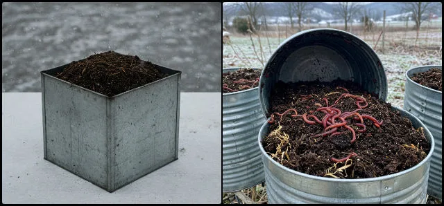
Cold temperatures can hinder vermiculture by slowing down worm activity and microbial decomposition. To maintain an effective composting system during winter, it is crucial to insulate, provide supplemental heat, and optimize internal heat generation. The following steps outline how to ensure smooth operations and protect the system in low-temperature conditions.
1. INSULATE THE SYSTEM
In colder temperatures, maintaining a warm environment for the worms is essential for continued composting. Insulating the system helps prevent the temperature from dropping too low and keeps the worms active. In a smaller system, this can be achieved by:
- Add Layers: Wrap the drawers filled with vermicomposting using insulating materials like straw bales, foam, old blankets, or bubble wrap, which helps to insulate the system.
- Buried Systems: Consider partially burying vermiculture drawers in the ground to leverage the earth’s insulating properties.
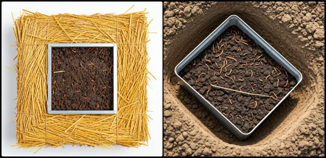
Since our system is already positioned 8 feet below ground level, additional burial will not be necessary. The doors will be well insulated, and the large size of the system, combined with the surrounding earth, provides natural thermal insulation, helping keep the internal temperature stable within the processing chamber.
However, if the temperature of the processing chamber drops below 45°F and no supplemental heat is available, wrapping foam around the entire processing chamber can be used as an emergency solution. Since the drawers are embedded into the collection area, layering each one individually is not practical. Wrapping the whole chamber is easier to manage and does not require moving the drawers.
Here’s a video about insulating our vermiculture system to maintain warmth:
VIDEO COMING: INSULATING VERMICULTURE SYSTEMS FOR COLD WEATHER
SEE OUR HOW TO HELP AND/OR CROWDFUNDING CAMPAIGN PAGE TO HELP CREATE ALL THE TUTORIAL VIDEOS FASTER
2. PROVIDE SUPPLEMENTAL HEAT
To maintain optimal temperatures in colder conditions, supplemental heat can be introduced. This helps ensure that the vermiculture system remains within the ideal temperature range for worm activity and decomposition. In traditional smaller systems, it is maintained by:
- Heating Mats: Place a seedling heat mat under or around the drawer. Heating mats can be set to 60°F so that they maintain the optimum temperature. Ensure they do not directly touch the worms to prevent overheating.
- Heat Lamps: Install a low-wattage heat lamp placed near the system. This can provide external heat to the vermiculture compound, ensuring optimal temperature in winter. Ensure it does not overheat or dry out the bedding.
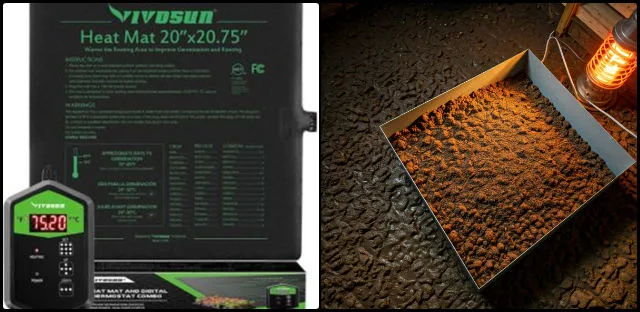
Since our vermiculture system is well insulated, as discussed above, such situations will rarely occur unless atmospheric temperatures drop significantly. The heat loss through the earthen walls depends on outside temperatures, for example, around 650 BTU/hr loss at 10°F and up to 930 BTU/hr at -10°F. Given the large size of our system, even when using supplemental heat, it would take time for noticeable changes to occur. Hence, it is more practical to ensure good thermal insulation of the chamber itself to minimize heat loss.
If the temperature inside the processing chamber begins to gradually drop toward 45°F, our system is equipped to respond proactively. The chamber temperature does not fall suddenly, allowing time for our monitoring system to detect and respond. Temperature sensors monitor both the ambient room conditions and internal chamber temperatures through probes placed at various depths. This real-time data is fed into an active monitoring and control device, which automatically activates heating elements, such as heat mats attached to the chamber walls or nearby heat lamps, when needed. This automated system ensures the internal temperature remains within the optimal range, preventing it from falling below 45°F while also minimizing energy waste by avoiding unnecessary overheating. The required heating power, outlined in the chart below, is based on calculated thermal losses of the surrounding earth material and serves as a guide for setting heat levels during colder conditions.
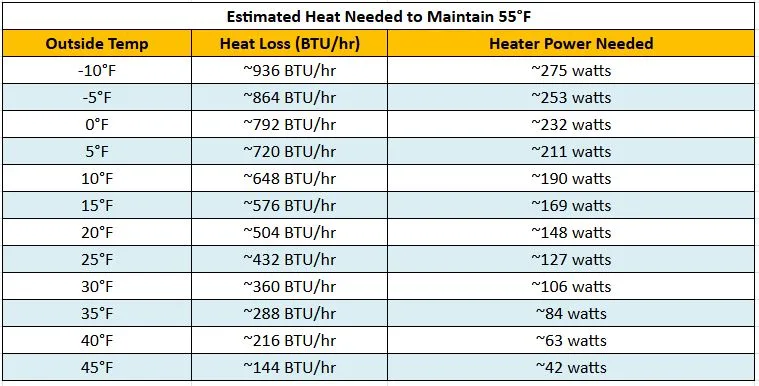
Click for source table
The goal is to maintain an optimal temperature around 55°F without overheating the system to ensure optimal processing by the worms when it starts getting cold outside. For our vermiculture setup, supplemental heating is the most effective way to handle extreme winter temperatures.
We will be conducting tests on the placement and performance of heating devices, sensors, and control devices in specific locations within the system. These tests aim to collect comprehensive data under real-world conditions to evaluate the system’s effectiveness in maintaining optimal temperatures and to refine the setup as needed for reliable long-term operation.
Here’s a video about temperature control setup for the vermiculture system:
VIDEO COMING: SUPPLEMENTAL HEAT FOR VERMICULTURE SYSTEMS IN WINTER
SEE OUR HOW TO HELP AND/OR CROWDFUNDING CAMPAIGN PAGE TO HELP CREATE ALL THE TUTORIAL VIDEOS FASTER
3. OPTIMIZE INTERNAL HEAT GENERATION
To boost internal heat generation in our vermiculture system, it is essential to encourage microbial activity and insulate the worms. Here are a few strategies to maintain optimal temperatures during colder periods, as traditionally used in smaller systems:
- Increase Waste Input: Add additional organic waste generated from the commercial kitchen of the city center into the vermicompost to encourage microbial activity, which generates heat as the material decomposes.
- Layering: In the vermicompost drawer, add thick layers of bedding or partially decomposed compost to insulate the worms and retain heat.
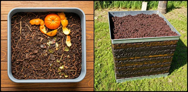
In our design, organic waste can be added directly from the top. Similarly, layering can be done by adding organic waste before and after using the toilet or at regular intervals of a few days to maintain a consistent balance of organic and compost waste. It is essential to ensure an optimal ratio between the collected waste and the added organic material, maintaining a proper nitrogen-to-carbon balance for effective composting. We will be fine-tuning the ratio, and it will be added here as results become available.
Here’s a video of the complete process of fine-tuning our compost ratio to optimize internal heat generation:
VIDEO COMING: FINE-TUNING THE COMPOST RATIO PROCESS FOR WINTER
SEE OUR HOW TO HELP AND/OR CROWDFUNDING CAMPAIGN PAGE TO HELP CREATE ALL THE TUTORIAL VIDEOS FASTER
5. ENHANCE WORM BEDDING
 To ensure worms thrive in colder conditions, enhancing the bedding can help create a comfortable and stable environment. By adjusting the bedding depth and using thermal materials, we can improve insulation and maintain the right conditions for the worms to thrive. In traditional systems, this is done by adding:
- Depth: Increase the bedding depth to create warm microenvironments where worms can burrow.
- Thermal Materials: Use materials like shredded newspaper, dry leaves, or coconut coir, which trap heat and regulate moisture.
In our vermiculture system, we have designed for a bedding depth of around 1 foot at the bottom, which is much deeper than typical small-scale setups. With a total area of about 90 square feet, the system allows the worms to move freely and form their own microenvironments. The depth and volume help buffer against cold external temperatures, making it unlikely for extreme cold to reach deep into the processing chamber. Since the system runs continuously, increasing bedding depth from the bottom is not practical, but as previously mentioned, additional layers can be added from the top as needed.
We plan to start the system in summer, giving the worms enough time to establish themselves before winter. By then, several feet of composted layers will have built up, providing natural insulation and allowing worms to burrow deeper if the upper layers get too cold. Throughout this process, carbon-rich materials like dry grass and wood shavings will continue to be added, especially in the early stages and periodically afterward, to maintain proper layering and insulation.
Here’s a video about adjusting worm bedding to ensure smooth operations in winter:
VIDEO COMING: ENHANCING WORM BEDDING FOR COLDER CONDITIONS IN VERMICULTURE SYSTEMS
SEE OUR HOW TO HELP AND/OR CROWDFUNDING CAMPAIGN PAGE TO HELP CREATE ALL THE TUTORIAL VIDEOS FASTER
6. MAINTAIN MOISTURE BALANCE
Maintaining the right moisture balance is crucial in colder temperatures to support healthy worm activity and effective composting by ensuring the compost does not get too wet. Proper moisture control helps prevent issues like waterlogging and anaerobic conditions. In smaller systems, it is achieved by:
- Prevent Overwatering: Reduce water input since evaporation is slower in colder conditions.
- Drain Excess Moisture: Ensure proper drainage to avoid waterlogging, which can create anaerobic conditions.
In our vermiculture system, moisture levels are generally high due to the nature of human waste. Even with a urine-separating toilet, there is a steady input of moisture. The perforated drawer bottoms and thick bedding layer help manage this by allowing excess liquid to drain while retaining enough moisture to keep the environment healthy for the worms.
During colder temperatures, moisture loss is less of a concern since decomposition slows and evaporation decreases. The layering technique, as discussed earlier, helps maintain balance by preventing compaction and promoting aeration. However, in winter, the main concern is that the compost may become too moist from the water content in human waste. This can be effectively managed by adding extra carbon or dry bedding material to absorb the excess moisture and maintain a healthy environment.
As part of our safety protocol, we will test the moisture runoff collected at the drawer level to ensure it does not carry harmful pathogens such as viruses, bacteria, or other contaminants. This testing will help verify that the system’s drainage design maintains hygienic conditions and prevents the spread of disease. Clear guidelines will also be provided on appropriate uses of the compost, such as soil amendment, landscaping, or agricultural use.
Here’s a video about the steps we take to maintain moisture balance in our vermiculture system, especially during colder temperatures:
VIDEO COMING: MAINTAINING MOISTURE BALANCE IN VERMICULTURE SYSTEMS FOR WINTER CONDITIONS
SEE OUR HOW TO HELP AND/OR CROWDFUNDING CAMPAIGN PAGE TO HELP CREATE ALL THE TUTORIAL VIDEOS FASTER
7. USE COLD-TOLERANT WORM SPECIES
To ensure optimal performance of the vermiculture system during the winter months, it is important to select worm species that can thrive in colder temperatures. Cold-tolerant worms will continue to decompose organic material efficiently even in lower temperatures.
Typically, in colder environments, worms like European Nightcrawlers (Eisenia hortensis) are used because they are more tolerant of cooler conditions compared to Red Wigglers and provide better decomposition efficiency.
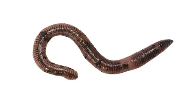
European Nightcrawlers
In our system, we will continue using both African Nightcrawlers, earthworms, and Red Wigglers during winter, as their complementary roles ensure efficient composting even in colder conditions. African Nightcrawlers, which thrive in deeper layers, will benefit from the retained warmth at the bottom of the processing chamber, maintaining their ability to break down large amounts of organic material. Meanwhile, Red Wigglers, which prefer the upper layers, will remain active in the cooler regions, though their activity may slow slightly. Together, they will sustain composting efficiency, prevent waste buildup, and contribute to the production of nutrient-rich compost, even in lower temperatures.
8. MONITOR THE SYSTEM
Regular monitoring of the system is essential to ensure the worms are in a stable environment. By keeping track of temperature and observing the worms, timely adjustments can be made to maintain optimal conditions. In traditional systems, this is done by:
- Regular Checks: Use a thermometer to monitor the system’s internal temperature and adjust measures as needed.
- Inspect Worms: Check for signs of stress, such as worms clumping or moving away from the bedding.
Traditional systems are typically located outdoors, making them more susceptible to environmental fluctuations. However, our system is housed indoors, providing a significant advantage in monitoring and controlling conditions. To ensure optimal performance, we plan to integrate an active temperature monitoring system. Since manually inspecting the worms is not feasible, remote monitoring will allow us to track environmental conditions effectively, ensuring the system remains stable without requiring additional effort.
EMERGENCY MEASURES IN LOW TEMPERATURE
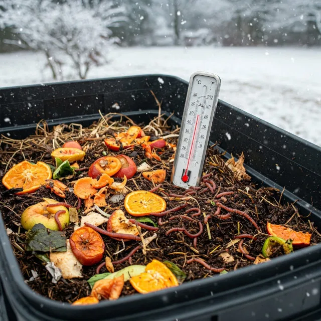 If the system becomes too cold, quick action is needed to prevent harm to the worms and ensure the composting process continues. Below are steps to restore optimal conditions.
If the system becomes too cold:
- Remove and relocate worms temporarily to a warmer area with fresh bedding.
- Introduce a heat source, such as heating pads or heat lamps, to restore suitable temperatures.
- Add partially decomposed compost to jumpstart microbial heating.
In our vermiculture system, we aim to minimize human intervention, so relocating worms or adding additional compost will not be necessary. Instead, supplemental heat can be used to maintain optimal temperatures for efficient vermicomposting.
VERMICULTURE COMPOSTING SCHEDULE AND CONSIDERATIONS
Given that the vermiculture processing unit takes about 6 months to fill and the waste is composted by worms, it is important to plan the schedule for emptying the containers to ensure smooth operations. Here is a suggested schedule along with factors to consider for optimal composting:
WHAT IS THE BEST TIME OF YEAR TO EMPTY
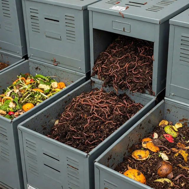 Proper timing is crucial for maintaining optimal conditions in the vermiculture system. Emptying thecomposted waste at the right time ensures that the worms stay healthy and that the composting process remains efficient.
Factors Influencing Emptying Time:
- Continuous Processing Design: The system is designed for continuous flow. This means that instead of a single, large harvest, the finished compost will be removed periodically as the drawers become full.
- “When Full” Indicator: The primary trigger for emptying a drawer is when it is full of mature compost. This eliminates the need to adhere to a strict seasonal schedule.
- Independent of Seasonal Variation: Because the system is indoors and temperature-controlled, the emptying schedule is less affected by external seasonal changes. The focus is on the compost’s maturity, not the time of year.
- Maintenance of Optimal Balance: By emptying the drawers when they are full, the system prevents overloading, which is essential for maintaining the balance of the vermicomposting process. This ensures that the worms have an optimal environment to continue their work.
General Guidelines:
- It is often recommended to allow the system to process waste for several months before a significant harvest.
- A common practice is to stop adding new waste for a week or two before emptying, allowing the worms to finish processing the remaining material.
- From the information provided in the report, the system being used is designed as a constant flow system. Therefore, the emptying of the drawers will happen when the drawers are full of finished compost. This will happen on a constant basis and will not be tied to a specific time of year.
Key Takeaways:
- Rather than a specific time of year, focus on the maturity of the compost.
- Consider the impact on worm activity and avoid extreme temperatures.
- With the system described in the report, emptying will occur when the drawers are full.
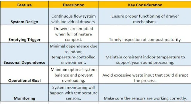
Click for source
ADDITIONAL CONSIDERATIONS FOR SMOOTH OPERATIONS
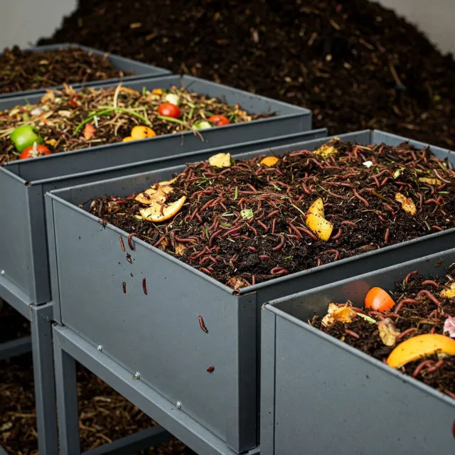 These are general guidelines to ensure the smooth functioning of a vermiculture system. By addressing key factors like temperature, moisture, pest control, and worm health, one can maintain an efficient and healthy composting environment year-round.
General Guidelines for Smooth Vermiculture Operation:
- Optimal Temperature Regulation: Maintaining a consistent temperature range conducive to worm activity.
- Adequate Moisture Control: Ensuring the bedding remains moist but not waterlogged.
- Proper Aeration: Providing sufficient oxygen for aerobic decomposition and worm health.
- Balanced Waste Input: Regulating the amount and type of organic waste to avoid overloading.
- Pest and Pathogen Management: Preventing infestations and maintaining a hygienic environment.
- Regular Monitoring: Observing the system for signs of imbalance or distress.
- Appropriate Bedding Material: Using suitable materials for moisture retention, aeration, and insulation.
- Efficient Drainage: Removing excess liquid to prevent anaerobic conditions.
Our system, housed underground in an insulated chamber, ensures stable temperatures through sensors and supplemental heating or cooling. Moisture is regulated by the waste’s natural content and a perforated drawer drainage system. Aeration is maintained through layered bedding materials, while controlled waste input prevents overloading. The indoor design minimizes pests, and continuous monitoring through sensors ensures balance. Dual worm species optimize processing, and layered bedding with efficient drainage supports a consistently effective composting process.
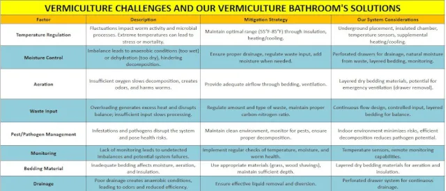
Vermiculture Challenges and Our Vermiculture Bathroom’s Solutions – Click for source table
Once the composting process is complete, laboratory testing of the processed material will be conducted to ensure it meets safety standards for agricultural use. Parameters to be tested include pathogen levels, such as E. coli and Salmonella, heavy metals, such as lead, cadmium, and arsenic, pH balance, nutrient content (NPK), moisture level, and the presence of any harmful organic compounds. Based on these results, clear guidelines will be provided on appropriate uses of the compost, such as soil amendment for non-edible plants, landscaping, or, if standards are met, safe use in food crop production. This step ensures the final product is both safe and environmentally beneficial.
VERMICULTURE SYSTEM TEMPERATURE CONTROL
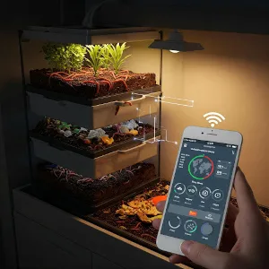 Temperature is a key factor in maintaining a successful vermiculture system, providing an optimal environment for worms to thrive and efficiently break down organic waste. Consistent monitoring and regulation are essential to ensure stable conditions, regardless of external climate variations. Our system features a below-ground processing chamber that naturally moderates temperature, reducing the risk of extreme fluctuations. However, active monitoring and control are still necessary to prevent harmful extremes that could stress or endanger the worms. Maintaining the right temperature supports microbial decomposition and worm activity, ensuring a stable, efficient composting process. By preventing temperature imbalances, we can optimize operations year-round, maximize nutrient-rich compost production, and contribute to a sustainable waste management solution.
TEMPERATURE MONITORING DEVICES
To ensure the smooth operation of our vermiculture system, it’s crucial to have an efficient temperature monitoring device that works in real-time. The monitoring system must meet key requirements to effectively manage temperature fluctuations and ensure optimal conditions for the worms. The device should be capable of integrating with Wi-Fi or other wireless communication systems to send real-time updates and alerts directly to multiple mobile phones. Additionally, it should offer customizable alert settings, allowing us to receive notifications when the temperature exceeds or falls below the ideal range. With these essential features in mind, several commercially available devices have been considered. Below is the list of all the devices ranked in order of preference for our vermiculture system.
- MOCREO WiFi Room Thermometer Hygrometer (3-Pack)
- X-Sense Wi-Fi Hygrometer (STH0A31)
- Necto Cellular Temperature & Humidity Monitor
- Temp Stick Remote WiFi Temperature & Humidity
- SwitchBot Wi-Fi Humidity Sensor
- TempIQ WiFi Temperature & Humidity Sensor
- Govee Hygrometer Thermometer H5100 (3-Pack)
In the table provided below, we have meticulously compared seven temperature and humidity monitoring devices based on their key features, assigning a score between 0 to 5 for each relevant attribute. Each device was evaluated across a wide range of criteria, including connectivity, temperature and humidity range, alert functionality, data storage and export options, battery life, mounting type, and additional features. These scores reflect each device’s performance, ease of use, and functionality, offering an objective comparison of their strengths and limitations. After evaluating all features, total scores were calculated to provide a comprehensive assessment of how each product performs relative to others. The devices were then ranked based on their total scores, clearly identifying the most effective and feature-rich solutions for temperature and humidity monitoring.
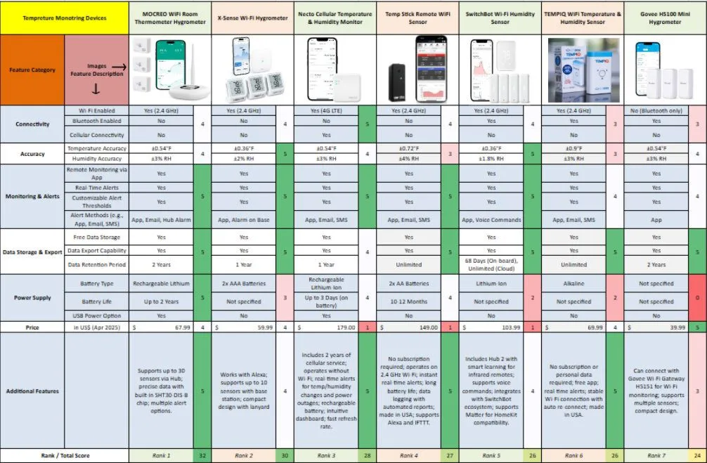
Comparison spreadsheet for Temperature monitoring devices – Click for source table
This detailed analysis provides a strong foundation for making informed decisions based on specific needs and priorities. In the following section, each device is discussed in detail to provide a complete evaluation and assess its compatibility with our system requirements.
MOCREO WIFI ROOM THERMOMETER HYGROMETER (3-PACK)
The MOCREO WiFi Room Thermometer Hygrometer has been selected as our top choice due to its strong balance of affordability, reliability, and functionality for vermiculture applications. It enables 24/7 remote monitoring through the MOCREO app and supports multiple sensors connected to a single hub, allowing comprehensive monitoring of both room and chamber conditions. With an accuracy of ±0.54°F and ±3% RH, it ensures precise environmental control. The device offers multiple alert options, including email, app notifications, and an 80dB hub alarm, providing immediate updates for any temperature or humidity fluctuations. Additionally, it includes two years of free data storage and a rechargeable battery with a lifespan of up to two years, making it a low-maintenance and cost-effective solution. Priced at $67.99, the MOCREO device stands out as a reliable long-term option for continuous vermiculture monitoring without recurring costs.
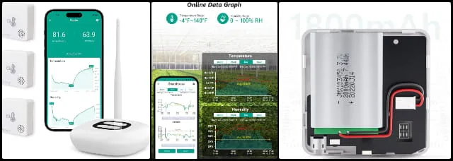
Mocreo WiFi Room Thermometer Hygrometer (3-Pack) Specifications
The data in the table below provide information about the WiFi room temperature hygrometer (3 pack) by MOCREO.
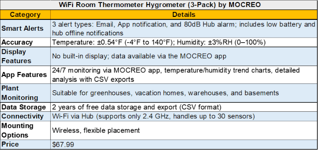
Click for source
X-SENSE WI-FI HYGROMETER (STH0A31)
Ranked second, the X-Sense Wi-Fi Hygrometer (STH0A31) offers high accuracy and smart connectivity at a competitive price of $59.99. It features a Swiss-made sensor for precise temperature and humidity readings, real-time alerts via a mobile app, and free cloud data storage with graphical analytics for trend monitoring. With a 1,700 ft range, it ensures seamless monitoring of the vermiculture processing chamber, though it is better suited for smaller setups. Although it offers great accuracy and long-range performance, it lacks multi-sensor support compared to Mocreo, making it less efficient for monitoring multiple chambers simultaneously.

X-SENSE WI-FI HYGROMETER (STH0A31) SPECIFICATIONS
The data in the table below provides information about the X-Sense Wi-Fi Hygrometer (STH0A31).
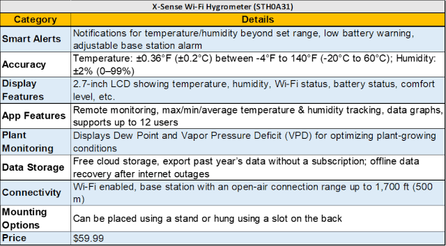
Click for source
NECTO CELLULAR TEMPERATURE & HUMIDITY MONITOR
The Necto Cellular Temperature & Humidity Monitor ranks third due to its 4G LTE connectivity, making it an excellent option for locations without stable Wi-Fi access. It provides real-time alerts for temperature, humidity, and power outages, ensuring that the vermiculture environment remains stable even during electrical failures. It includes two years of free cellular service, after which it can be renewed for $29.99 per year, making it a cost-effective long-term solution. The built-in 3-day rechargeable battery ensures continued monitoring during outages. Though priced at $179, its robust features, fast data refresh rate, and customizable alerts make it ideal for remote or outdoor vermiculture setups.
Although the Necto Cellular Monitor works without Wi-Fi and is ideal for remote areas, its higher cost ($179) and annual renewal fee ($29.99) make it more expensive than X-Sense, which offers Wi-Fi-based connectivity at a lower cost.

NECTO CELLULAR TEMPERATURE & HUMIDITY MONITOR SPECIFICATIONS
The data in the table below provides information about the Necto Cellular Temperature & Humidity Monitor.
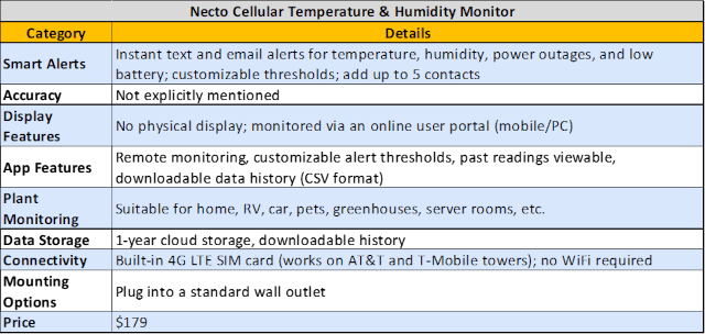
Click for source
TEMP STICK REMOTE WIFI TEMPERATURE & HUMIDITY
Ranked fourth, the Temp Stick Remote WiFi Sensor is a high-end, subscription-free monitoring device with excellent accuracy (±0.4°C, ±4% RH). It offers unlimited cloud data logging, real-time alerts via text, email, and app notifications, and a long battery life of 10–12 months, reducing maintenance needs. Manufactured in the USA with dedicated customer support, it is designed for reliability and durability. However, at $149, it is significantly more expensive than Mocreo and X-Sense. While it offers strong monitoring capabilities with no hidden costs, it relies solely on Wi-Fi, making it less versatile than Necto’s cellular-based connectivity.
TEMP STICK REMOTE WIFI TEMPERATURE & HUMIDITY SPECIFICATIONS
The data in the table below provides information about the Temp Stick Remote WiFi Sensor.
Click for source
SWITCHBOT WI-FI HUMIDITY SENSOR
Ranked fifth, the SwitchBot Wi-Fi Humidity Sensor is a versatile, IP65 waterproof device with precise temperature, humidity, dew point, and VPD readings. Its rugged design supports both indoor and outdoor use. It connects via SwitchBot Hub 2 and integrates with Alexa, Google Home, Siri, and SmartThings for automation. With real-time alerts and free cloud storage, it ensures reliable monitoring. Priced at $103.99, it offers strong features, but its dependence on a hub and higher cost make it a secondary option.
Although SwitchBot offers smart home integration and waterproofing, it requires an additional hub, making Temp Stick a simpler and more user-friendly option.
SWITCHBOT WI-FI HUMIDITY SENSOR SPECIFICATIONS
The data in the table below provides information about the SwitchBot Wi-Fi Humidity Sensor.
Click for source
TEMPIQ WIFI TEMPERATURE & HUMIDITY SENSOR
The TempIQ WiFi Temperature & Humidity Sensor is a reliable device offering real-time alerts via text, email, and push notifications with no subscription fees. It provides stable Wi-Fi connectivity and unlimited free data storage for continuous monitoring. Priced at $69.99, it is cost-effective but lacks advanced smart home integrations and automation features. Its slower refresh rate makes it less responsive to rapid changes.
Although TempIQ offers Wi-Fi connectivity and alerts, it lacks waterproofing and smart home compatibility found in SwitchBot.
TEMPIQ WIFI TEMPERATURE & HUMIDITY SENSOR SPECIFICATIONS
The data in the table below provides information about the TempIQ WiFi Temperature & Humidity Sensor.
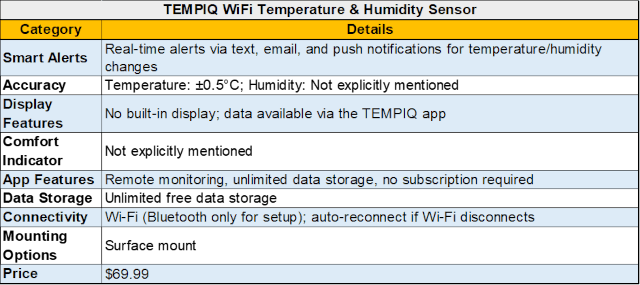
Click for source
GOVEE HYGROMETER THERMOMETER H5100 (3-PACK)
The Govee Hygrometer Thermometer H5100 (3-Pack) is a budget-friendly Bluetooth sensor with an accuracy of ±0.54°F and ±3% RH. It provides app-based monitoring, smart alerts, and 20-day free cloud storage, with optional extended data export. However, its Bluetooth-only connectivity limits remote access, making it less suitable for large or multi-chamber setups. Wi-Fi functionality requires an additional gateway, increasing cost. Priced at $39.99, it is an affordable entry-level option but lacks scalability.
Although Govee is the most budget-friendly option, it relies on Bluetooth instead of Wi-Fi, making it less practical for remote monitoring compared to TempIQ.
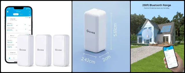
GOVEE HYGROMETER THERMOMETER SPECIFICATIONS
The data in the table below provides information about the Govee Hygrometer Thermometer H5100 (3-Pack).
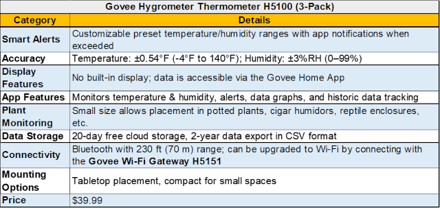
Click for source
SUMMARY
After conducting a comprehensive analysis of various temperature and humidity monitoring devices, we evaluated each option based on the specific needs of our vermiculture processing system. Our primary objectives include real-time monitoring, remote access, customizable alerts, and seamless integration with Wi-Fi or cellular connectivity. Additionally, the devices must provide reliable data storage, ease of use, and compatibility with the chamber environment. Based on these criteria, we identified the MOCREO Wi-Fi Room Thermometer Hygrometer as the optimal solution. It offers accurate monitoring, Wi-Fi connectivity through a hub, multiple alert options, long battery life, and two years of free cloud storage, making it a cost-effective choice at $67.99. Its ability to monitor multiple sensors through a single hub further enhances its suitability for the system’s scale and flexibility.
However, in case the MOCREO device is unavailable, we identified two strong alternatives. The X-Sense Wi-Fi Hygrometer (STH0A31) provides a reliable and accurate solution at an affordable price of $59.99, offering real-time alerts and cloud data storage. Its pricing and features make it a solid backup option. On the other hand, the Necto Cellular Temperature & Humidity Monitor, priced at $179, offers 4G LTE connectivity, making it ideal for locations with unstable Wi-Fi. While more expensive, its cellular service and continuous monitoring provide added reliability in environments where Wi-Fi access is limited.
Since technology continues to evolve and new devices frequently enter the market, there may be more advanced or cost-effective options available at the time of purchase. To address this, we created a detailed comparison spreadsheet that allows new devices to be evaluated alongside existing options using the same set of criteria. This approach ensures consistent analysis and helps determine whether the current recommendation—the MOCREO Wi-Fi Room Thermometer Hygrometer—should be replaced by a newer, more suitable option. As new products emerge, they will be added to the spreadsheet to support informed and confident purchasing decisions.
TEMPERATURE CONTROL DEVICES
Maintaining a stable and optimal temperature is essential for the efficiency of our vermiculture processing system. While real-time temperature monitoring helps track fluctuations, effective temperature control is crucial to prevent stress or harm to the worms. External environmental changes, seasonal variations, and internal microbial activity can lead to unexpected shifts in temperature within the composting chambers.
Our system is designed to naturally regulate temperature as it is built into the ground, insulated by earth on three sides, and enclosed with thick walls and a door on one side. This setup provides a strong thermal barrier, ensuring a well-regulated environment. Since the processing chamber is situated below ground, past the frost line, it benefits from the earth’s natural insulating properties and maintains a dependable internal temperature of around 55°F. Under normal conditions, external heating or cooling is unnecessary. In winter, keeping the chamber sealed helps retain warmth, while in summer, opening the door improves ventilation by utilizing cooler underground temperatures.
Another important factor is the system size, spanning approximately 90 square inches of surface area. This large compost volume helps buffer temperature changes by slowing fluctuations. The mass retains heat during colder periods and creates microenvironments where worms can move to favorable zones. If internal temperatures rise due to microbial activity, the system’s exposed surface area and surrounding structure help dissipate excess heat. Due to this thermal mass and below-ground placement, only prolonged extreme conditions significantly impact internal temperature.
However, in cases of extreme temperatures, external heating or cooling measures may be required. To address this, the system integrates a simple temperature control setup using exhaust fans for cooling and heat mats or lamps for heating. These components are managed by a controller device that switches between heating and cooling based on temperature thresholds, maintaining system stability.
Smart thermostats further enhance automation by reducing manual intervention. Integrated monitoring systems can trigger ventilation, heating, or cooling automatically based on predefined conditions. This improves composting efficiency, reduces operational effort, and minimizes risks from temperature fluctuations. Remote or programmable systems also allow real-time adjustments, increasing reliability and resource efficiency.
Based on the requirements above, we evaluated several commercially available temperature control devices. Below is the ranked list of selected devices:
- WILLHI WH1436A 10A Digital Temperature Controller
- Bayite BTC211 Temperature Controller
- Inkbird ITC-308 Digital Temperature Controller
- Inkbird ITC-1000 Digital Temperature Controller
- Eurotherm 500 Advanced Temperature Controller and Programmer
- Johnson Controls A421ABC-02C Electronic Temperature Control
In the table below, we compared each temperature controller based on key features required for the vermiculture system. Each feature was scored from 0 to 5 based on functionality, safety, performance, ease of use, and cost. Final scores were calculated to rank the devices and identify the most suitable option. Detailed analysis for each device is provided in the following sections.
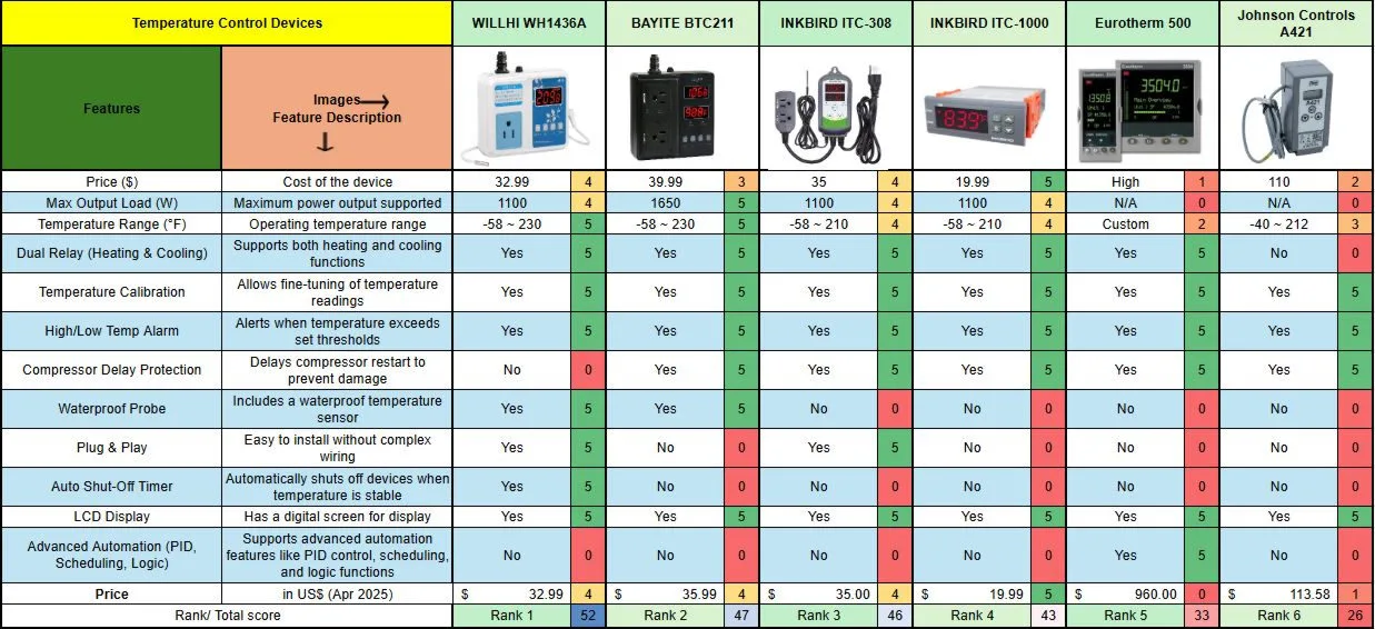
Temperature control devices – Click for source
WILLHI WH1436A 10A DIGITAL TEMPERATURE CONTROLLER
The WILLHI WH1436A 10A Digital Temperature Controller is an affordable and effective solution for regulating the temperature in our vermiculture system. Priced at $32.99, this plug-and-play thermostat is ideal for seamlessly switching between heating and cooling modes based on the set temperature. Its maximum load of 10A (1100W) is suitable for controlling devices such as heaters, cooling fans, and ventilation systems, ensuring the composting environment remains within the optimal temperature range.
Here, the plug-and-play functionality stands out as a major advantage, as it gives us the flexibility to easily test and switch between different heating and cooling devices without needing to rewire or replace the controller itself. With two separate universal outlets—one for heating and one for cooling—it is incredibly convenient to set up and adjust as needed. This flexibility is especially useful during the initial stages of system setup or when making seasonal adjustments.
We ranked this as the best option because it offers the best combination of features, ease of use, and reliability. It supports both heating and cooling with dual relay control, includes temperature calibration, alarms, and an LCD, making it highly versatile across different applications.
PROS FOR THIS TEMPERATURE CONTROLLER
- Highest score among competitors.
- User-friendly plug & play design.
- Supports both heating & cooling.
- Reliable and easy-to-use.
CONS FOR THIS TEMPERATURE CONTROLLER
- No compressor delay protection.
- No waterproof probe.
- No advanced automation features.
BAYITE BTC211 TEMPERATURE CONTROLLER
The Bayite BTC211 Temperature Controller is an excellent choice for managing temperature control in our vermiculture system, offering a robust and reliable solution for precise environmental regulation. With its dual relay output, this thermostat can simultaneously control both heating and cooling systems, ensuring a stable temperature range that meets the requirements of the composting process. The device’s high output load of 1650W (110V-240V) ensures it can handle multiple devices, such as heaters, fans, and cooling units, providing flexibility and scalability for our system as it grows.
This comes in second because it offers a higher max output (1650W), wide temperature range (-58°F to 230°F), compressor delay protection, and dual relay support. It is ideal for industrial and high-power applications. However, when compared with WILLHI WH1436A, the Bayite BTC211 is better suited for high-power use cases, whereas the WILLHI WH1436A is more user-friendly for home setups. The WILLHI WH1436A is plug-and-play, while the Bayite BTC211 requires manual wiring. Additionally, the Bayite BTC211 includes compressor delay protection, which the WILLHI WH1436A lacks.
PROS FOR THIS TEMPERATURE CONTROLLER
- Highest max output load (1650W).
- Wide temperature range.
- Safety features like compressor delay protection.
- Temperature calibration & alarms.
CONS FOR THIS TEMPERATURE CONTROLLER
- No waterproof probe.
- No advanced automation features.
INKBIRD ITC-308 DIGITAL TEMPERATURE CONTROLLER
The Inkbird ITC-308 Digital Temperature Controller is a versatile and cost-effective solution for managing temperature control within our vermiculture system. With its dual relay output, it allows seamless operation of both heating and cooling devices, making it ideal for adjusting temperature levels in response to fluctuations. The device’s ability to display both the measured and set temperatures in real time ensures easy monitoring, while the high/low temperature alarms provide an additional layer of safety by alerting us to potential issues. This feature is particularly useful in maintaining optimal conditions for the worms, ensuring they are not exposed to harmful temperature extremes.
This is our third choice because it offers a well-balanced option with dual relay heating and cooling functionality. However, compared to Bayite BTC211, the Bayite BTC211 supports a higher power load (1650W), while the INKBIRD ITC-308 has a lower maximum load. The INKBIRD ITC-308 is easier to set up (pre-wired), whereas the Bayite BTC211 requires manual wiring. Additionally, the Bayite BTC211 has a wider temperature range, while the INKBIRD ITC-308 operates within a more standard range.
PROS FOR THIS TEMPERATURE CONTROLLER
- Easy to use and set up.
- Reliable for home applications.
- Good safety features like compressor delay protection.
CONS FOR THIS TEMPERATURE CONTROLLER
- No waterproof probe.
- No plug & play functionality.
- No advanced automation features.
INKBIRD ITC-1000 DIGITAL TEMPERATURE CONTROLLER
The Inkbird ITC-1000 All-Purpose Digital Temperature Controller presents a budget-friendly and reliable option for temperature management within our vermiculture system. This device’s dual relays allow it to control both heating and cooling functions, making it well-suited for maintaining the necessary temperature range for the composting process. Its programmable thermostat offers flexibility to adjust settings based on environmental fluctuations, ensuring optimal conditions for the worms. Additionally, the temperature calibration function allows for fine-tuning, improving accuracy in maintaining desired temperature levels within the processing chamber.
We ranked this lower at fourth place because, while it supports dual-relay heating and cooling and is budget-friendly, it lacks plug-and-play features and compressor delay protection. Compared to the INKBIRD ITC-308, the ITC-308 is easier to set up with pre-wired connections, while the ITC-1000 requires manual wiring. The INKBIRD ITC-308 also includes compressor delay protection, which the ITC-1000 lacks.
PROS FOR THIS TEMPERATURE CONTROLLER
- Affordable price.
- Reliable for basic applications.
- Supports both heating and cooling.
CONS FOR THIS TEMPERATURE CONTROLLER
- No waterproof probe.
- No plug & play functionality.
- No compressor delay protection.
EUROTHERM 500 ADVANCED TEMPERATURE CONTROLLER AND PROGRAMMER
The Eurotherm 500 Advanced Temperature Controller and Programmer (3504, 3508 Series) is a high-precision, industrial-grade temperature control solution that can be integrated into our vermiculture system for maintaining optimal composting conditions. With its ability to regulate temperature and other process variables, this controller ensures a stable environment for microbial activity, which is crucial for efficient organic decomposition. Its dual PID loops allow for independent heating and cooling control, enabling precise adjustments based on temperature fluctuations. Additionally, the 50 programmable profiles provide automation of temperature changes over time, reducing the need for constant manual monitoring.
This ranks at fifth position because while it offers advanced PID control and automation features, it lacks clear information on max output load and temperature range and is expensive. Compared to the INKBIRD ITC-1000, the Eurotherm 500 is better suited for industrial automation, while the ITC-1000 is more practical for our vermiculture system. The Eurotherm 500 supports PID control and scheduling, which the ITC-1000 lacks, but the ITC-1000 is much more affordable and easier to use.
PROS FOR THIS TEMPERATURE CONTROLLER
- Ideal for industrial and automation applications.
- Advanced PID and logic control.
CONS FOR THIS TEMPERATURE CONTROLLER
- Expensive.
- Max output load and temperature range are not clearly defined.
- No waterproof probe.
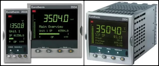
JOHNSON CONTROLS A421ABC-02C ELECTRONIC TEMPERATURE CONTROL
The Johnson Controls A421ABC-02C Electronic Temperature Control is a robust and industrial-grade thermostat that can be integrated into our vermiculture system for precise temperature regulation. With a wide temperature range of -40 to 212°F (-40 to 100°C) and a single-pole double-throw (SPDT) output relay, this device is suitable for controlling either heating or cooling equipment with high accuracy. Its durable design supports long-term use in environments requiring consistent temperature maintenance, ensuring that the composting unit remains within optimal conditions for microbial activity and organic breakdown.
This is our sixth choice because the device lacks dual relay support, meaning it cannot control both heating and cooling simultaneously. It also has a narrower functional range compared to higher-ranked controllers. Compared to the Eurotherm 500, it lacks advanced automation features and does not support dual relay operation for heating and cooling.
PROS FOR THIS TEMPERATURE CONTROLLER
- Decent safety features.
- Simple interface.
CONS FOR THIS TEMPERATURE CONTROLLER
- No dual relay (heating and cooling).
- Lower temperature range (-40 to 212°F).
- No waterproof probe.
- No plug & play functionality.
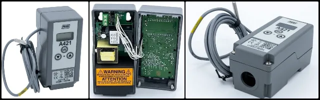
SUMMARY
In our research on temperature control solutions for our vermiculture system, we analyzed a range of thermostats and digital controllers that can efficiently regulate heating, cooling, and ventilation based on set temperature thresholds. Maintaining an optimal temperature range is crucial for microbial activity and overall composting efficiency, reducing the risk of overheating or excessive cooling that could hinder the decomposition process. We considered key factors such as price, ease of use, automation capabilities, sensor accuracy, safety features, and power efficiency to ensure seamless operation without constant manual intervention. The selected devices range from cost-effective plug-and-play solutions to advanced programmable controllers that allow for greater customization and integration into automated systems.
After a thorough evaluation, the WILLHI WH1436A stands out as the best choice for temperature control in our vermiculture system. Its plug-and-play design, dual relay system for heating and cooling, LCD, and temperature calibration features make it both user-friendly and highly efficient. Priced at $32.99, it provides excellent accuracy and safety features, ensuring optimal composting conditions with minimal manual intervention.
As alternatives, the BAYITE BTC211 offers higher power output and robust control, making it suitable for users who require more precise temperature adjustments, though it requires manual wiring. Meanwhile, the INKBIRD ITC-308 provides an easy-to-use, cost-effective option with a dual relay system, compressor delay protection, and high/low-temperature alarms, making it a great plug-and-play solution for reliable temperature management.
VENTILATION SYSTEM DESIGN FOR VERMICOMPOSTING ECO-TOILET SPACE
A ventilation system is needed to maintain air quality, control temperature, and remove moisture and odors from enclosed spaces. It ensures a continuous supply of fresh air, prevents the buildup of harmful gases or heat, and supports occupant comfort and system efficiency. In systems like vermiculture toilets, proper ventilation is essential to sustain aerobic composting and prevent foul odors or microbial growth.
We discuss this in the following sections:
- What Is This Ventilation System?
- Why Is This Important?
- Ducting, Filtration, and Support Frame Design
- Fan and Filter Placement Strategies
- Assembly
- Result and Discussion
WHAT IS THIS VENTILATION SYSTEM?
This report documents the design, structural validation, and performance assessment of the HVAC system developed for the vermiculture toilet module under the One Community project. The system integrates ducting, filter, and fan assemblies to ensure effective air circulation, odor control, and thermal balance for the composting environment. The design uses a modular structure that supports ease of installation and maintenance while maintaining energy efficiency and low-noise operation.
The image below illustrates the precise spatial arrangement and integration of the HVAC components within the vermiculture unit. This side-elevation view highlights the positioning of the ducting, filter, and fan assemblies relative to the vermicomposting modules, showing how the system is routed to optimize air circulation and odor control while remaining accessible for installation and maintenance.
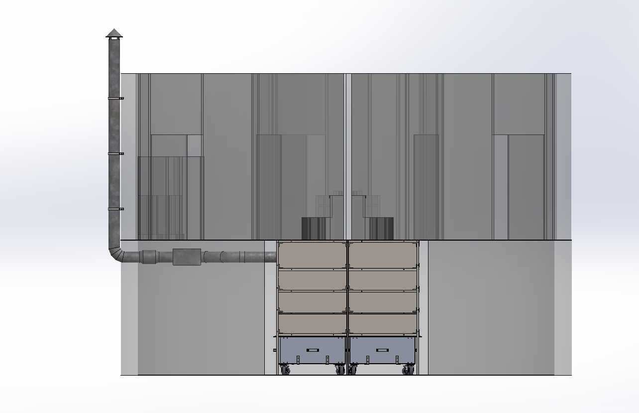
Figure 1: Side-elevation view of integrated HVAC and vermicomposting modules showing component positioning and duct routing – Click to Enlarge
WHY IS THIS IMPORTANT?
Effective ventilation is crucial for maintaining an aerobic environment in vermiculture toilets, which directly influences composting rate, odor management, and user comfort. Without adequate airflow, harmful gases accumulate, moisture levels rise, and the composting process degrades all of which compromise both system performance and occupant safety. This HVAC design addresses these risks through the following key functions:
- Regulates humidity and air exchange rates to maintain optimal composting conditions.
- Prevents buildup of harmful gases and excess moisture within the enclosed composting space.
- Improves system longevity by reducing corrosion and inhibiting microbial growth on structural surfaces.
- Enhances sustainability through low-power operation and the use of recycled or durable materials.
DUCTING, FILTRATION, AND SUPPORT FRAME DESIGN
The ducting network is designed to maintain a consistent negative pressure environment, ensuring that all processed air is directed through the specialized filtration assembly before being exhausted. This assembly is supported by a modular frame designed to withstand the vibration of the fan units while providing easy access for routine filter maintenance. By integrating these mechanical systems within the structural Unistrut layout, I have ensured that the HVAC components do not interfere with the primary waste-processing areas while still delivering maximum ventilation efficiency.
DUCTS
In mechanical engineering and HVAC design, a duct is a specialized conduit or passage used to deliver and remove air. For the Earthbag Village vermiculture project, the ducting network is a critical component that ensures effective air circulation, odor control, and thermal balance within the composting environment.
DUCT-TO-DUCT FLANGED ADAPTER
Duct-to-duct flanged adapters are used to connect quick-disconnect ducts to other duct types, including standard round, spiral, or flanged ducts. The flange interface creates a secure, tight seal between different duct systems, ensuring reliable airflow continuity at each junction point. The image below shows the dimensional drawing for the Size 8 flanged adapter used in this system.
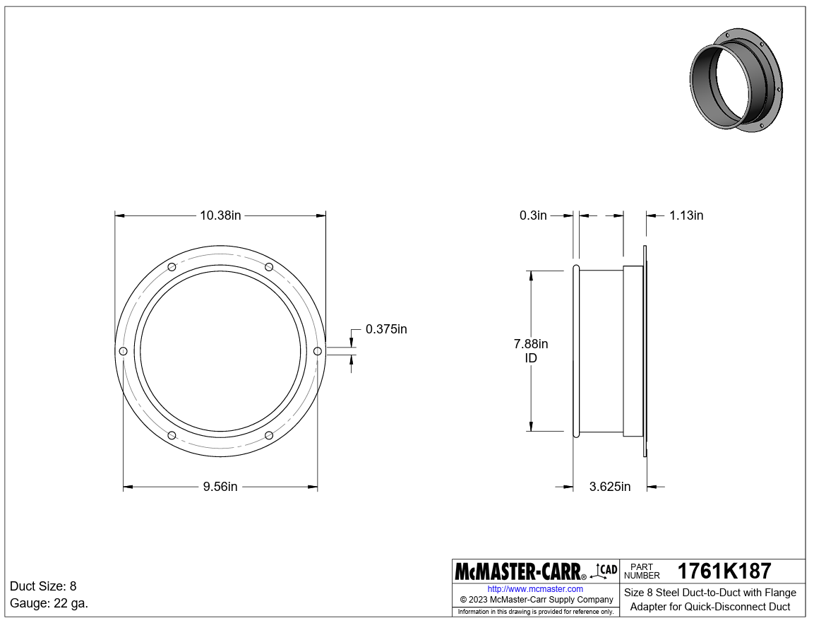
Figure 2.1: Size 8 duct-to-duct flanged adapter dimensions showing flange profile and connection geometry – Click to Enlarge
GALVANIZED STEEL DUCT
Two galvanized steel duct lengths are used in this system to accommodate both short and extended airflow runs. Both sections feature a 7-7/8 inch outer diameter male end and an 8-inch inner diameter female end, using a slip-fit connection for smooth, leak-free assembly. The 24-gauge galvanized steel construction provides corrosion resistance suitable for the moisture-laden composting environment.
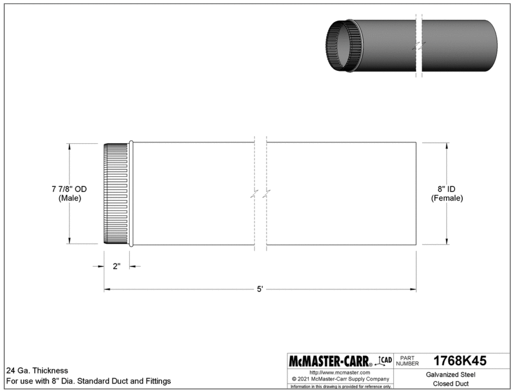
Figure 2.2: Size 8 galvanized steel duct, 2-foot length. Used for short runs and tight spaces in the HVAC layout – Click to Enlarge
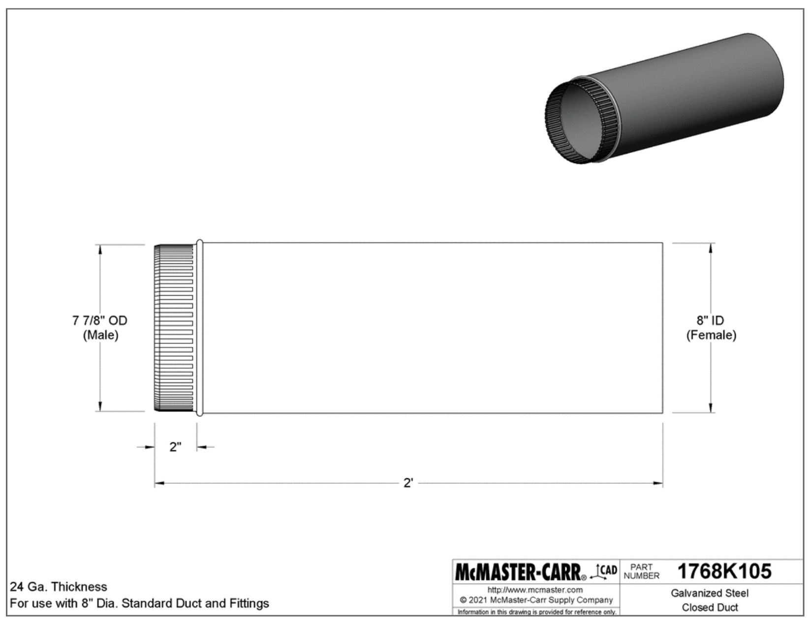
Figure 2.3: Size 8 galvanized steel duct, 5-foot length. Provides an extended airflow path while minimizing the number of joints – Click to Enlarge
90-DEGREE WYE CONNECTOR DUCT
The selected Y-connector is the Vent Systems 8-inch Y-Shape Duct Connector, a three-way hose adapter designed for use with extractor fans and duct hose systems. This fitting provides a practical and cost-effective solution for splitting airflow within the ventilation system, accommodating the required duct routing configuration. The 8-inch diameter ensures compatibility with the existing ductwork and supports adequate airflow distribution across the connected branches.
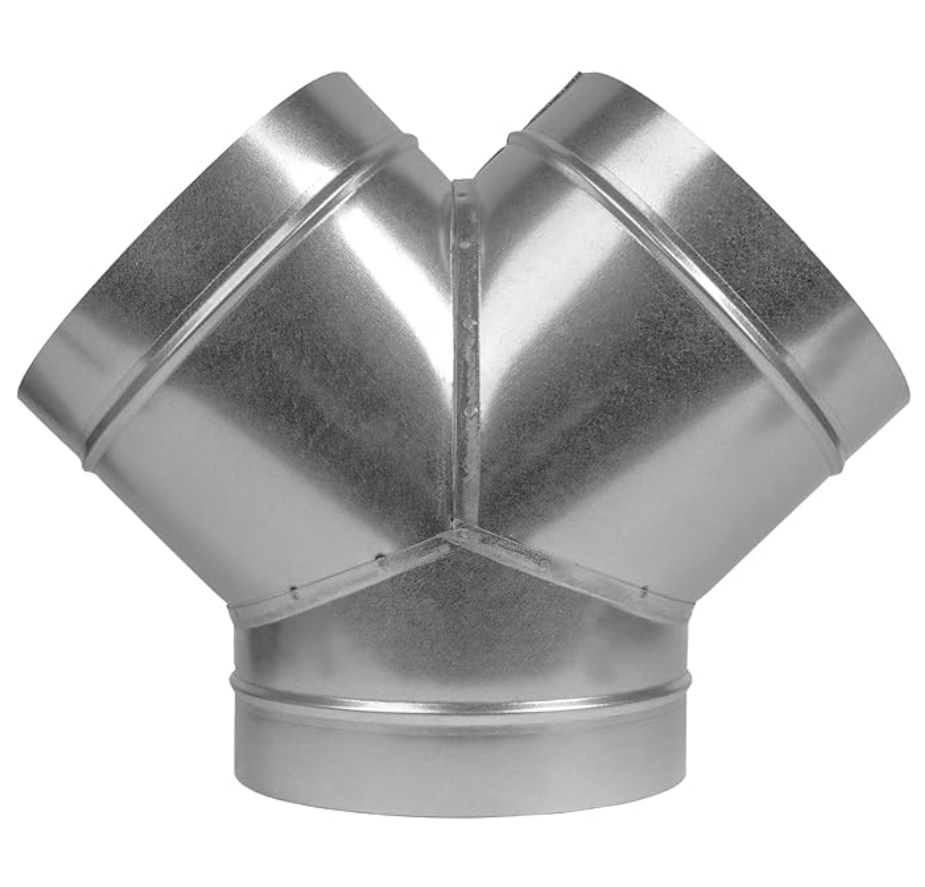
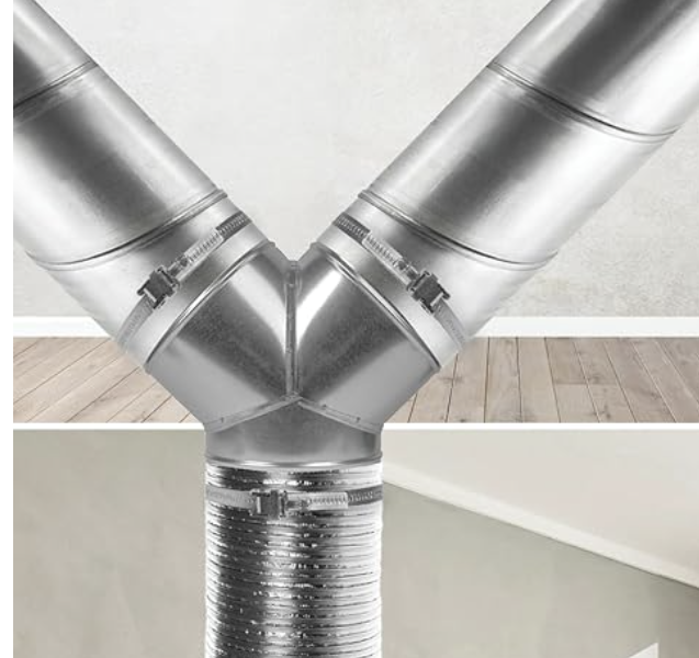
Figure 2.5: Size 8 galvanized steel 90-degree elbow connector, adjustable from angled to straight configuration – Click to Enlarge
GALVANIZED STEEL 90-DEGREE ELBOW DUCT
The 90-degree elbow connector is used to redirect airflow at right angles within the duct network. Its segmented design allows the shape to be adjusted by twisting individual sections, providing flexibility in routing during installation.
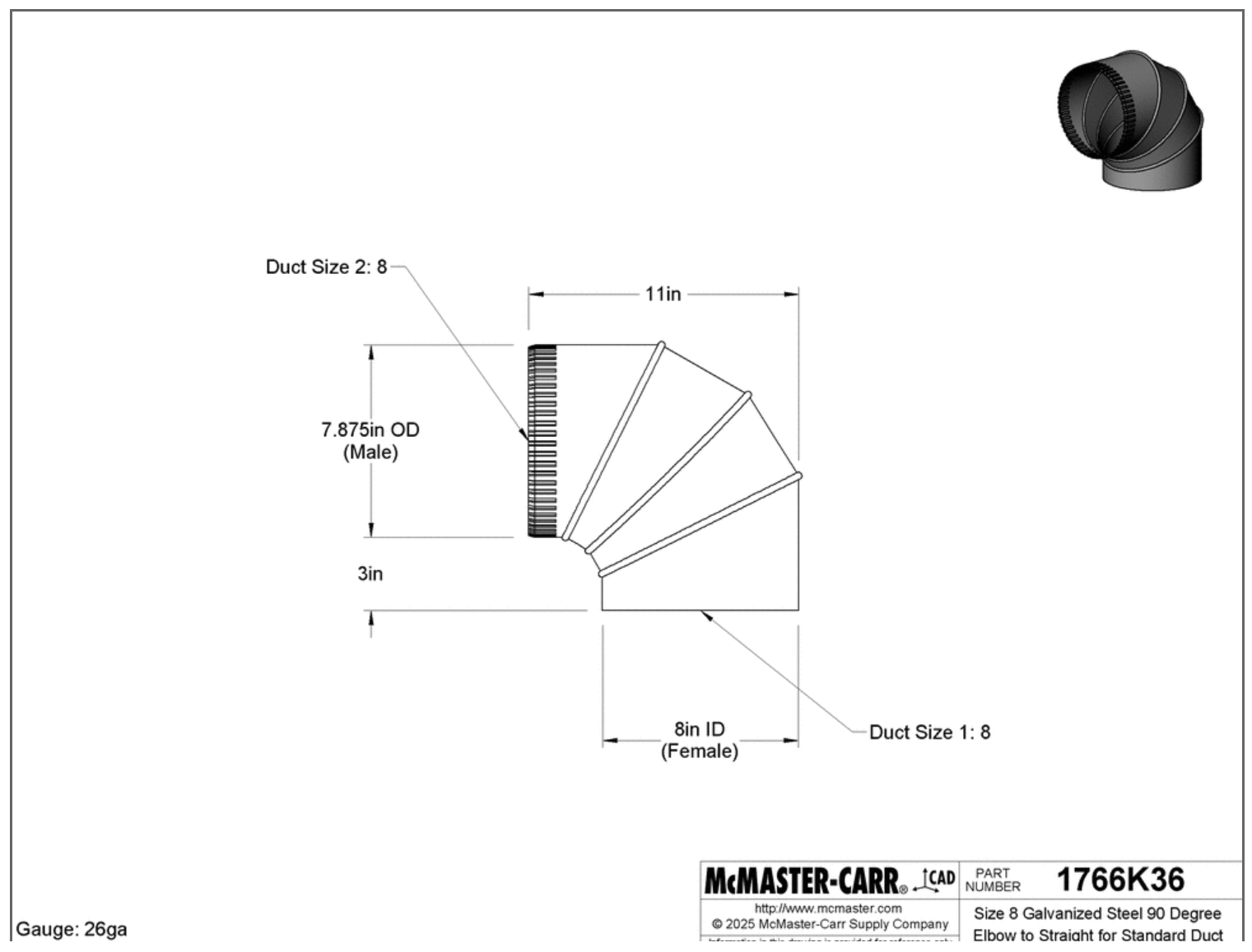
Figure 2.5: Size 8 galvanized steel 90-degree elbow connector, adjustable from angled to straight configuration – Click to Enlarge
STEEL RAIN CAP
The steel rain cap is fitted to the top of the vertical exhaust duct to prevent rain, debris, and dust from entering the ventilation system. By protecting the duct opening from the elements, the rain cap reduces the risk of internal corrosion and blockages, maintaining consistent airflow through the exhaust path.
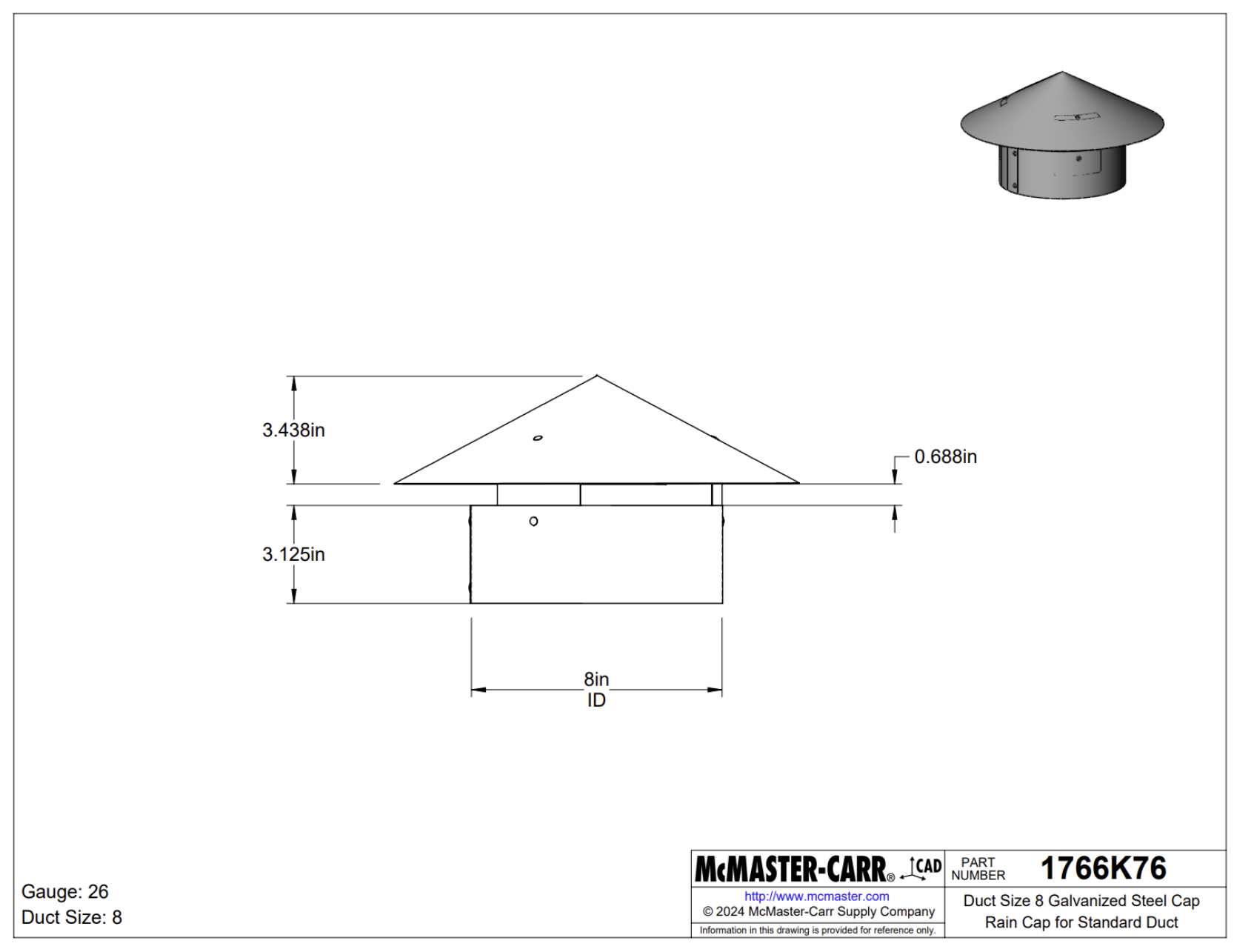
Figure 2.6: Size 8 galvanized steel rain cap fitted to the vertical exhaust duct to prevent water and debris ingress – Click to Enlarge
MATERIAL SELECTION
Material selection for the HVAC system was driven by the need for corrosion resistance, structural durability, and long-term performance in a moisture-rich composting environment. Two primary materials are used across the system, each assigned to the component type it best serves:
- Galvanized steel — Used for all duct components. Galvanized steel provides high strength, cost-effectiveness, and reliable corrosion resistance for handling continuous airflow and moisture exposure. Its smooth internal surface also supports efficient airflow and reduces maintenance frequency.
- Stainless steel SS304 — Used for all support hangers and clamps. SS304 offers superior corrosion resistance, high load-bearing strength, and long-term durability under sustained load in humid or outdoor environments. This ensures that the duct network remains securely mounted throughout the system’s service life.
This combination of materials provides a balanced solution that optimizes performance, longevity, and cost-efficiency across all components of the ventilation system.
FAN AND FILTER PLACEMENT STRATEGIES
In an HVAC system, the strategic placement of fans and filters is essential for maintaining air quality and system efficiency. For the vermiculture unit, these components are integrated to ensure effective air circulation and odor control within a modular framework. The placement strategy prioritizes continuous airflow through the compost chamber while protecting mechanical components from particulate contamination.
FAN
A centrifugal fan was selected at a 402 CFM rating as it provides sufficient airflow capacity to effectively manage the moisture and heat generated within the composting chamber. Centrifugal fans are particularly suited for this application due to their ability to maintain consistent static pressure against the resistance of ducting, filters, and bends within the ventilation system. The 402 CFM rating was determined based on the chamber volume and the required air exchange rate to sustain an optimal aerobic composting environment while preventing the buildup of excess humidity and odor.

Figure 2.7: Size 8 402 CFM incline centrifugal fan used for continuous exhaust at the rear outlet of the ventilation system.
Once operational, we’ll be providing tutorial videos like the one below for all aspects of operation and maintenance too.
VIDEO COMING: HOW TO INSTALL AND SERVICE THE HVAC FAN UNIT
SEE OUR HOW TO HELP AND/OR CROWDFUNDING CAMPAIGN PAGE TO HELP CREATE ALL THE TUTORIAL VIDEOS FASTER
When installing or servicing the HVAC system, always disconnect the power supply and wear protective gloves and eyewear. Sharp metal edges and moving fan blades can cause injury if handled carelessly. Ensure all ducts and hangers are securely fastened before testing the system.
FILTER
Activated carbon filters are positioned upstream of the fan between the duct inlet and the fan inlet to trap dust, moisture, and organic particulates before they reach the fan blades. This configuration protects the fan motor, extends its operational life, and minimizes odor release at the exhaust outlet. The image below shows the activated carbon filter box and its dimensional drawing.
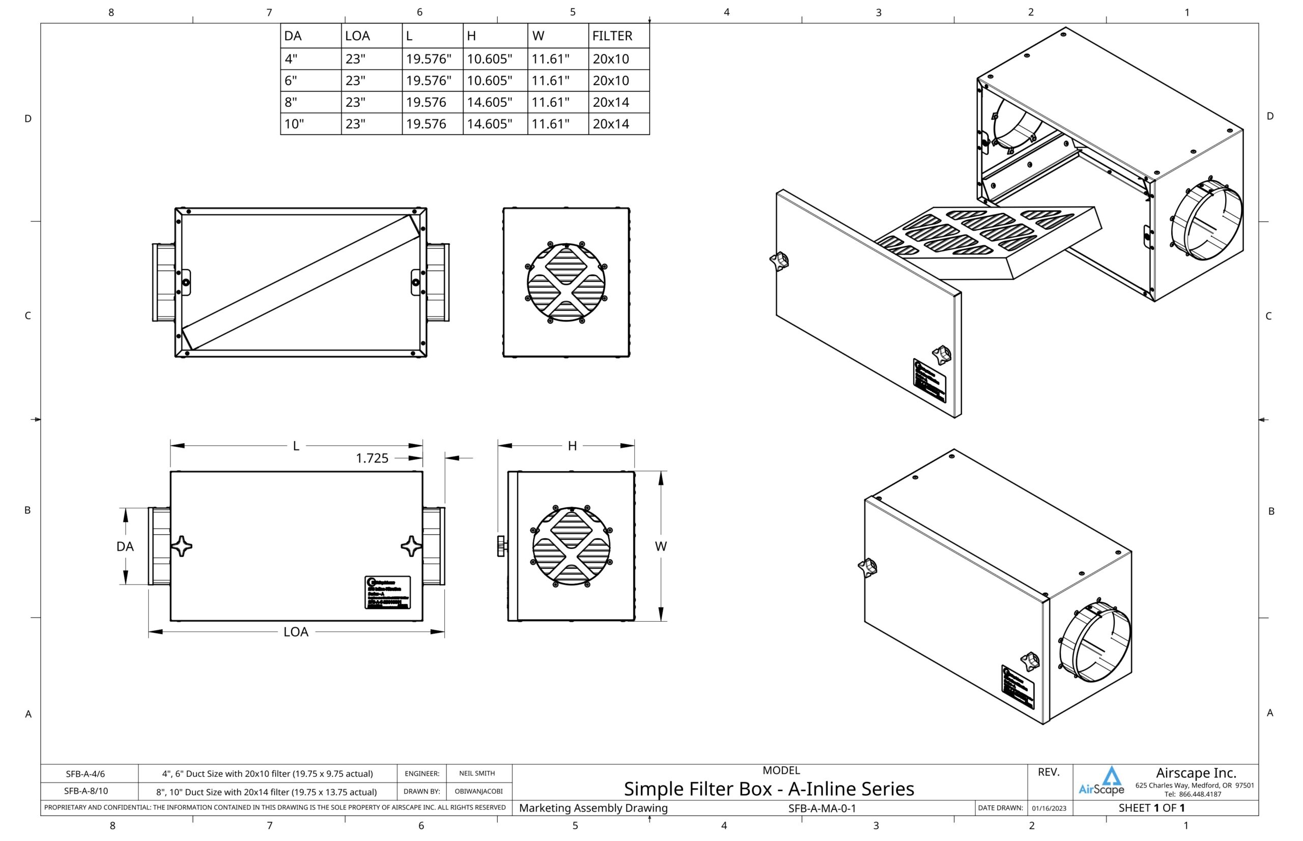
Click to Enlarge
VIDEO COMING: HOW TO HANDLE AND REPLACE FILTERS
SEE OUR HOW TO HELP AND/OR CROWDFUNDING CAMPAIGN PAGE TO HELP CREATE ALL THE TUTORIAL VIDEOS FASTER
When handling or replacing filters in the filtration box, always switch off the fan to prevent accidental suction or debris release. Wear gloves and a dust mask to avoid contact with trapped particles. Ensure the lid is properly sealed before restarting the system to maintain safe and efficient airflow.
SUPPORT FRAME
The duct support system uses an adjustable standoff clamp to secure round ducts to walls or ceilings while maintaining a small gap between the duct and the mounting surface. This standoff gap allows for thermal expansion, airflow around the duct exterior, and easier inspection during maintenance. The image below shows the standoff clamp technical drawing and its key components.
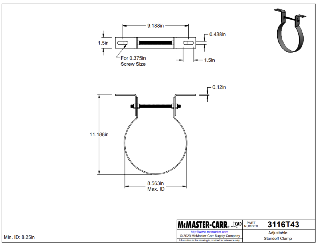
Adjustable standoff clamp technical drawing – Click to Enlarge
The clamp assembly consists of three primary elements: a flat metal strap that wraps around the duct to hold it firmly in position, a vertical threaded rod that provides adjustable height and alignment, and a nut-and-washer assembly at the top that locks the position and allows fine-tuning during installation. The clamp is made from durable steel and provides strong support, vibration resistance, and long-term stability for HVAC and ventilation ducts.
ASSEMBLY
The complete HVAC duct assembly integrates all individual components ducts, connectors, filter box, fan, and supports into a unified, functional system. The setup is designed to ensure smooth airflow, straightforward maintenance access, and secure mounting for both horizontal and vertical duct orientations. The image below shows the full assembled layout with all components in their final installed positions.
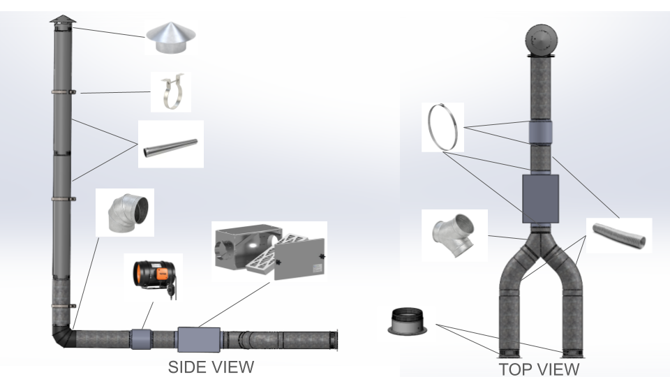
Figure 2.11: Complete HVAC duct assembly layout showing all components from air intake to final exhaust – Click to Enlarge
The labeled components in the assembly represent the complete ventilation path from air intake to final exhaust. The nine key components integrated in this assembly are as follows:
- Duct-to-duct flanged adapter – Connects the filter box outlet to the main duct network
- Galvanized steel ducts (2 ft and 5 ft) – Form the primary airflow conduits through the system
- 90-degree Y-connectors – Split or join airflow at branch points within the duct network
- 90-degree elbow to straight connectors – Redirect airflow at right angles along the duct path
- Steel rain cap – Protects the vertical exhaust outlet from rain, debris, and dust
- Incline fan (402 CFM) – Drives continuous airflow through the system from the rear outlet
- Filter box (activated carbon) – Traps particulates and odors upstream of the fan
- Pipe standoff clamps – Secure all duct sections to walls and ceilings with adjustable alignment
- Worm-drive clamps – Provide a tight, adjustable seal at all duct-to-fitting connections.
SPATIAL CONSTRAINTS & CLEARANCES
To ensure the ventilation system is compatible with the physical layout of the One Community eco-toilet module, a spatial integration study was conducted. This analysis verifies that the ductwork placement does not interfere with the operation of the vermicomposting bins or the structural integrity of the facility.
The vertical exhaust stack is positioned to clear the primary structure while maintaining a direct path for the 402 CFM fan. The horizontal runs are elevated to allow for the full range of motion required to slide the composting drawers in and out for maintenance. The image below provides detailed CAD measurements of the critical clearance dimensions.
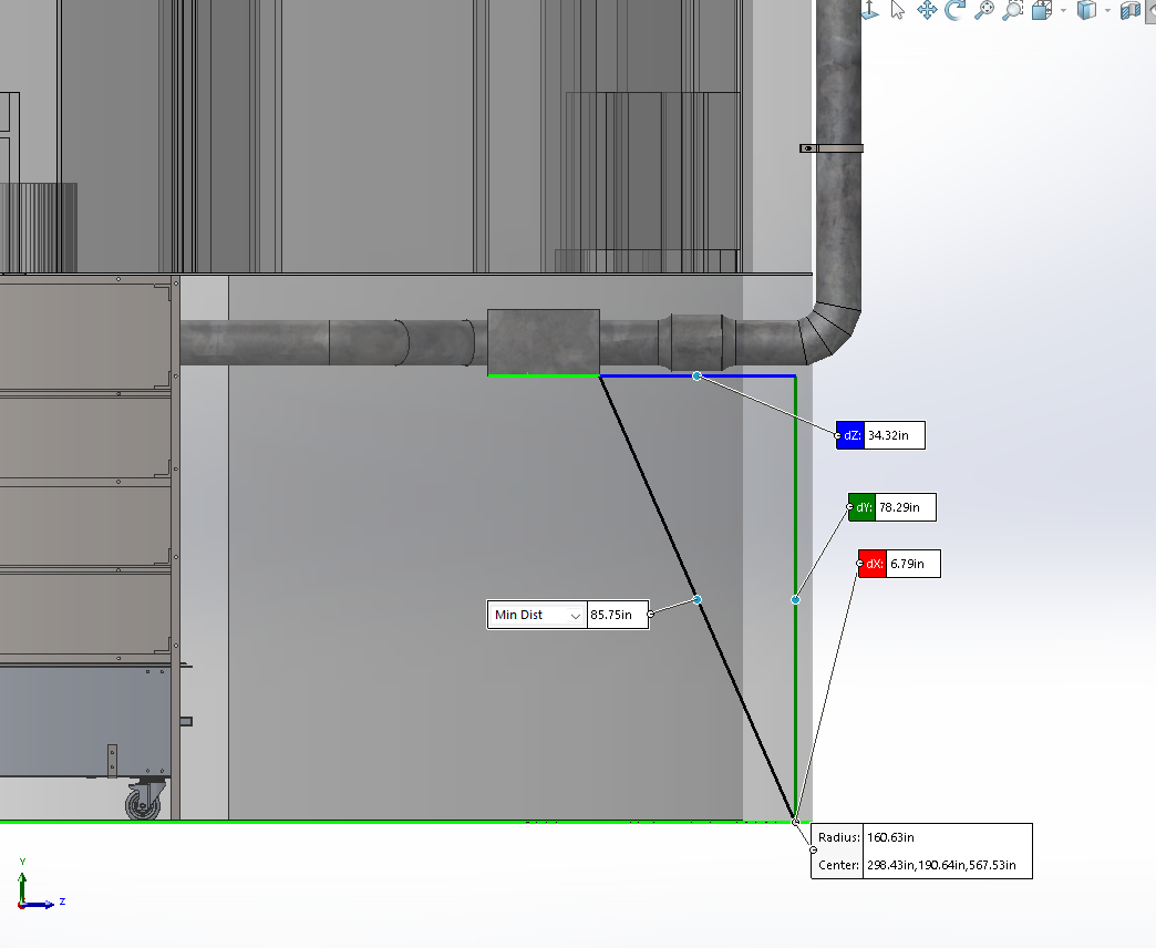
Figure 2.13: Detailed CAD measurement showing critical clearances and duct trajectory within the eco-toilet module – Click to Source
The table below summarizes the three key dimensional verifications confirmed through the spatial analysis, referenced against Figure 2.13:
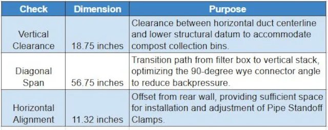
Table 1: Key dimensional verifications for spatial constraints and clearances (reference Figure 2.13) – Click to source
These constraints ensure that the HVAC system remains service-friendly, allowing filters to be changed and ducts to be inspected without dismantling the composting modules.
RESULT AND DISCUSSION
The performance of the ventilation system was evaluated through Computational Fluid Dynamics (CFD) analysis conducted in SolidWorks Flow Simulation. The study assessed pressure distribution, velocity distribution, and overall flow behavior across the full duct network. The results confirm that the system achieves the design targets of low pressure loss, uniform velocity, and effective odor control under the rated 402 CFM operating condition.
CFD (COMPUTATIONAL FLUID DYNAMICS) MODEL
A steady-state internal airflow analysis was conducted in SolidWorks Flow Simulation to evaluate pressure loss, velocity distribution, and flow uniformity within the ventilation ducts. The model included all major components: the duct network, 90-degree elbow, 90-degree wye connectors, and the 2-inch carbon MERV 8 filter modeled as a porous medium to simulate flow resistance. The inlet was defined at the lower duct region with an airflow rate corresponding to the 402 CFM centrifugal fan, and the outlet was defined at the top of the vertical duct at atmospheric pressure. Air properties were set at 25 degrees Celsius and 1 atm. The image below shows the flow trajectories through the filter box and duct section as computed in the simulation.
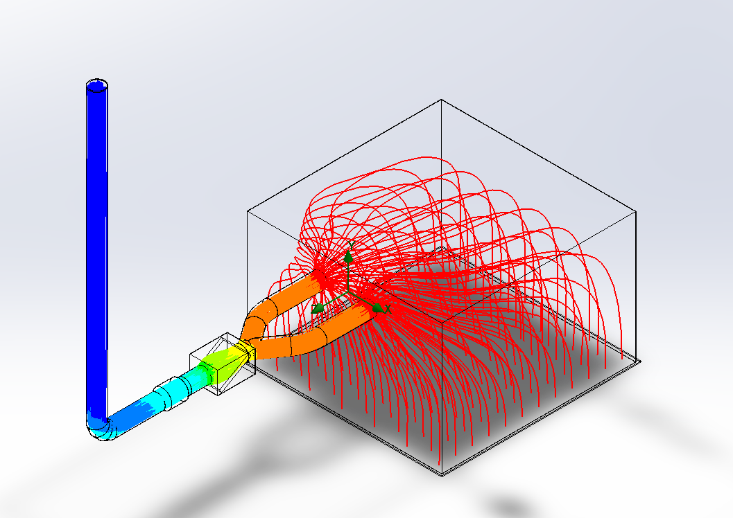
Figure 3.3: CFD flow trajectories through the filter box and duct section showing airflow direction and distribution under steady-state conditions – Click to source
PRESSURE DISTRIBUTION
The static pressure contour results show that pressure decreases gradually from the fan outlet through the wye connectors and up the vertical duct. The following key observations were recorded from the pressure distribution analysis:
- The highest pressure region of approximately 101,594 Pa occurs near the fan outlet and filter interface, where airflow impinges directly on the porous filter medium.
- A steady pressure drop of approximately 150 Pa is observed along the full system length, indicating smooth airflow with minimal energy losses.
- The wye section effectively divides airflow symmetrically, with balanced pressure recovery on both outlet branches.
The image below shows the static pressure contour plot across the full duct network. The results confirm that the duct geometry and filter placement minimize back pressure while maintaining consistent flow toward both branches.
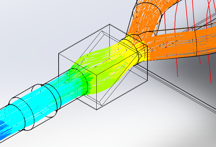
Static pressure contour distribution across the full duct network showing pressure gradient from fan outlet to exhaust – Click to enlarge
VELOCITY DISTRIBUTION
The velocity contour results illustrate uniform air movement through the ducts, with peak velocity zones at the fan inlet and elbow transitions. The following key values were recorded from the velocity distribution analysis:
- Maximum velocity: approximately 9 m/s at the fan outlet.
- Average velocity: approximately 5 m/s through the main duct sections.
- Flow transitions around elbows and wye connectors are smooth, demonstrating well-guided redirection with limited turbulence.
At the exhaust outlet, flow trajectories remain straight and uniform, confirming effective mixing and minimal recirculation zones. The vertical duct maintains consistent velocity throughout its length, demonstrating that the system can sustain continuous exhaust flow with low resistance.
FLOW BEHAVIOR
Detailed CFD visualizations were used to examine local turbulence patterns and flow dispersion at the critical transition points within the duct network. Two specific regions were analyzed for their flow behavior characteristics:
- Elbow region: Minor secondary flow and vortex formation occur due to the change in flow direction. However, this dissipates quickly downstream and does not significantly affect overall system performance.
- Filter box region: Moderate flow dispersion occurs as air passes through the porous carbon filter medium. This dispersion contributes positively to odor capture efficiency and promotes even airflow redistribution before the flow merges at the wye connector.
The image below shows the flow behavior near the elbow and filter regions, illustrating the local turbulence patterns and their downstream recovery.
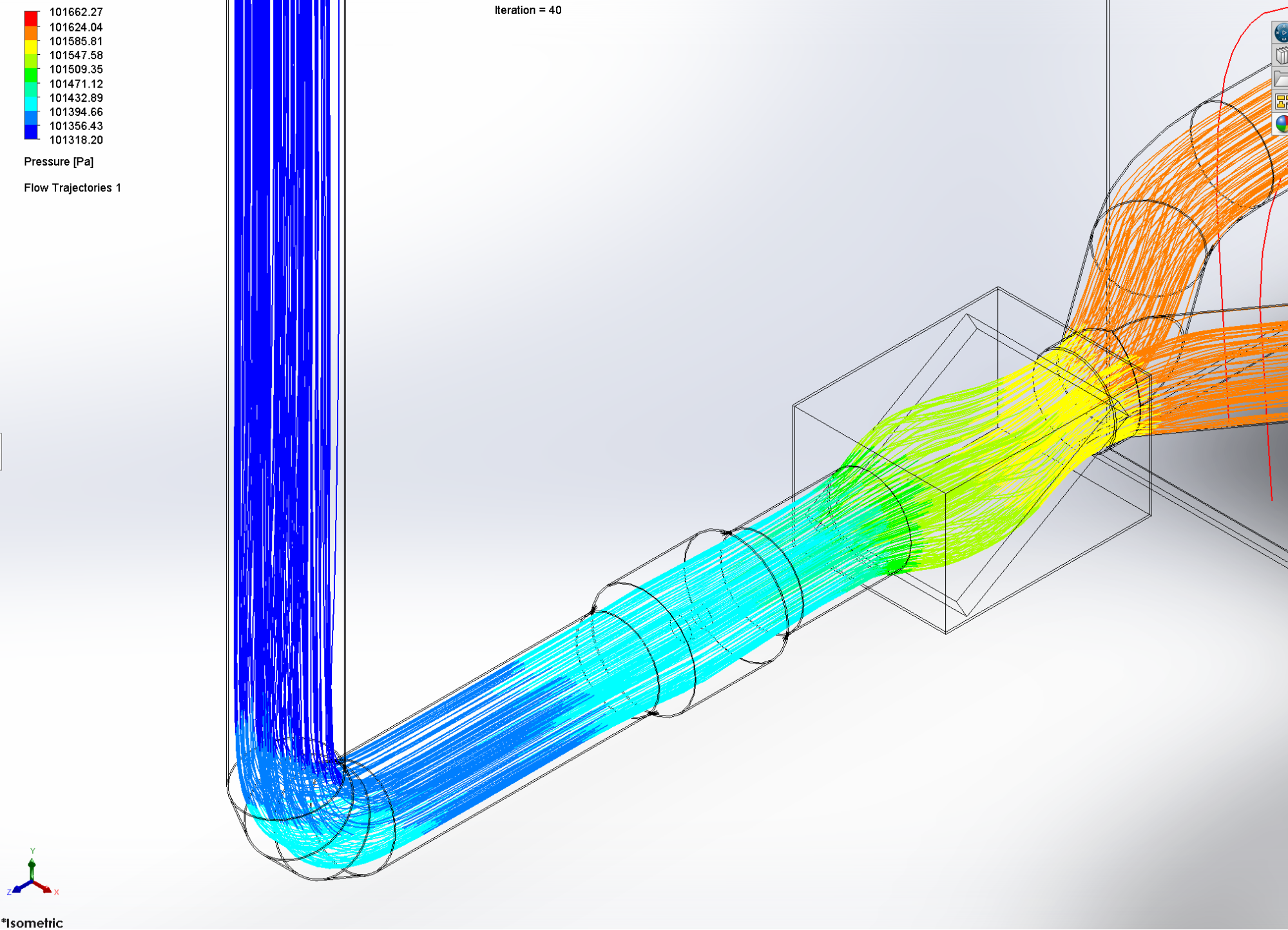
CFD visualization of flow behavior near the elbow and filter regions showing vortex formation and downstream dissipation – Click to enlarge
CONCLUSION
The ventilation system developed for the vermicomposting eco-toilet successfully meets the design goals of safety, performance, and sustainability. The structural analysis confirmed that the duct and hanger assembly remains stable under static and dynamic loads, with minimal stress and deflection across all components. The CFD analysis validated effective airflow management, with low overall pressure loss and uniform velocity distribution ensuring continuous, odor-controlled operation and optimal composting conditions throughout the module.
The use of galvanized steel for ductwork and SS304 stainless steel for support hardware provides long-term corrosion resistance suited to the moisture-rich composting environment. The MERV 8 activated carbon filtration provides reliable air purification at the point of exhaust, protecting both the fan motor and the surrounding space from particulate and odor release. The modular construction of the system allows for straightforward assembly, routine inspection, and future expansion as the facility grows.
Overall, the ventilation system design is mechanically reliable, energy-efficient, and environmentally sustainable, aligning with the goals of the One Community project to create self-sufficient, eco-friendly sanitation solutions.
FREQUENTLY ASKED QUESTIONS
Why Is a Negative Pressure Environment Used in the Ducting Design?
A negative pressure environment ensures that all air within the composting space is drawn through the filtration system before being exhausted. This prevents odors or harmful gases from escaping through gaps or openings in the structure, as air always flows inward toward the lower-pressure duct network rather than outward into the surrounding space.
Why Was a 402 CFM Fan Chosen for This System?
The 402 CFM (cubic feet per minute) rating was selected to provide sufficient airflow to maintain aerobic composting conditions across all four vermicompost compartments simultaneously. This capacity ensures adequate fresh air supply and exhaust of moisture-laden air without over-pressurizing the system or creating excessive noise during operation.
What Is the Purpose of the MERV 8 Activated Carbon Filter?
The MERV 8 activated carbon filter serves two functions: it physically captures dust, moisture droplets, and organic particulates that would otherwise damage the fan motor, and it chemically adsorbs odor compounds from the exhaust air stream before it is released to the atmosphere. Positioning the filter upstream of the fan protects the mechanical components and ensures that the exhaust air meets acceptable odor standards.
How Often Should the Filters Be Replaced?
Filter replacement frequency depends on the composting load and ambient conditions. Under normal operating conditions with the full 2,300 kg payload, filters should be inspected every 3 months and replaced when airflow resistance increases noticeably or when the filter medium becomes visibly saturated. The modular filter box design allows replacement without dismantling any other part of the duct system.
Why Is Galvanized Steel Used for Ducts Rather Than PVC or Plastic?
Galvanized steel was selected over PVC or plastic alternatives due to its superior resistance to the elevated temperatures, moisture, and biological activity present in a vermiculture environment. Plastic ducts can degrade or deform under sustained heat and humidity, whereas galvanized steel maintains its structural integrity and smooth internal surface over the full service life of the system.
Can the Ventilation System Be Expanded to Serve Additional Composting Modules?
Yes. The modular duct network is designed with expansion in mind. Additional wye connectors and duct sections can be integrated at the branch points to extend the system to serve additional compartments or modules. The 402 CFM fan capacity should be re-evaluated against the expanded airflow demand, and an upgraded fan unit may be required if the total ventilated volume increases significantly.
COOLING/VENTILATION DEVICES FOR VERMICULTURE COMPOST
In addition to heating solutions, we also explored cooling and ventilation devices to ensure year-round temperature stability in the vermiculture compost system. Although our composting setup is located below ground and surrounded by earth, which naturally helps maintain internal temperatures around 55°F (even during periods of high external heat), there may still be occasional needs for active cooling. This section addresses those possibilities and prepares us with a strategy if intervention becomes necessary.
The cooling and ventilation devices would be designed to activate only when required, ensuring efficiency and minimal energy usage. Integrated with a temperature controller, they would operate automatically if internal temperatures rise above the optimal range for vermiculture health. This approach keeps the system self-regulating, prevents stress on the worm population, and minimizes manual oversight, helping to maintain ideal composting conditions even during extreme weather fluctuations.
Below is a list of all the cooling and ventilation devices we explored for this project. In the following section, we will go through each option in detail to identify the most suitable one based on performance, features, and compatibility with our setup.
- AC Infinity Cloudline Pro T6, Quiet 6” Inline Duct Fan
- iPower Smart Ventilation Inline Fan
- TerraBloom 6 Inch Quiet Grow Tent Fan
- VIVOSUN Grow Tent Ventilation System
- VIVOSUN R8 8 Inch Inline Duct Ventilation Fan
- VIVOSUN Z8 8 Inch Inline Duct Fan
- SunStream 8 Inch Inline Duct Fan
AC INFINITY CLOUDLINE PRO T6, QUIET 6” INLINE DUCT FAN
This is our first choice, the AC Infinity CLOUDLINE PRO T6 is a premium inline duct fan priced at $159.00, designed specifically for controlled environment agriculture, like hydroponic grow rooms, but its versatility also makes it an excellent candidate for our vermiculture compost system. Featuring a 6” duct size, this unit delivers a strong airflow of 402 CFM while maintaining an impressively low noise level of just 32 dBA. It’s powered by a PWM-controlled EC motor, ensuring energy efficiency and quiet operation — two critical factors for our system’s smooth functioning.
This device fully satisfies all six of our requirements, including precise automation, smart controls, low noise, and compatibility with external temperature sensors. It’s purpose-built for environments needing dynamic climate regulation and offers the most complete package for a composting system.
PROS FOR THIS VENTILATION DEVICE
- Smart WiFi control and app integration for remote management.
- Ultra-quiet operation at just 32 dBA.
- Highly energy-efficient EC motor.
- Dynamic climate programming (temperature, humidity, VPD).
- Strong 402 CFM airflow suitable for large systems.
CONS FOR THIS VENTILATION DEVICE
- Higher upfront cost compared to simpler ventilation fans.
- Requires WiFi setup and app familiarity for full feature access.
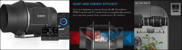
AC Infinity CLOUDLINE PRO T6
IPOWER SMART VENTILATION INLINE FAN
Ranked second, the iPower Smart Ventilation Inline Fan ($109.99) is a versatile system that integrates temperature and humidity control with a Wi-Fi app and voice control via Alexa. It includes a 6-inch fan with an airflow of 402 CFM at 34 dB and is powered by a Pulse Width Modulated (PWM) controlled EC motor for low noise and energy efficiency. The 6-inch carbon filter features 1200+ IAV Australian RC412 activated carbon for effective odor control, and the package also includes 8 feet of high-quality PVC ducting and metal clamps.
This system aligns with our needs by providing precise control over temperature and humidity in our vermiculture compost setup. The ability to control fan speed and monitor conditions remotely via Wi-Fi ensures that the system operates efficiently only when needed, keeping the internal temperature optimal and preventing overheating.
It was ranked second because it is smart, energy-efficient, and quiet, but it lacks advanced programmable control features like VPD, humidity integration, and real-time response to multiple conditions — making it slightly less adaptable to nuanced composting climate control.
PROS FOR THIS VENTILATION DEVICE
- Smart control via Alexa and Wi-Fi.
- Low power consumption and quiet operation.
- Effective odor control with a high-quality carbon filter.
- Flexible and durable ducting.
CONS FOR THIS VENTILATION DEVICE
- Requires a stable Wi-Fi connection for smart control.
- Relatively higher price for the features provided.
- Limited to smaller setups due to ducting length.
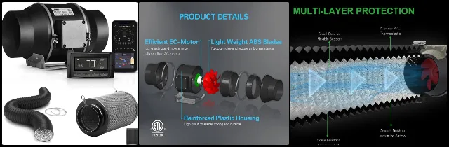
TERRABLOOM 6 INCH QUIET GROW TENT FAN
Ranked third, the TerraBloom 6 Inch Quiet Grow Tent Fan ($94.99) is designed for versatility, offering a 0-100% variable speed control with an eco-friendly EC motor that ensures low energy consumption and quiet operation. This fan delivers 288 CFM of airflow at 36 watts and operates at a low noise level of 31 dB. The fan can be adjusted using a variable speed controller or upgraded with a wireless remote or intelligent thermostat controller for more precise control.
This system aligns with our vermiculture needs by providing efficient cooling and ventilation for large composting areas without consuming excess energy. Its low noise and flexible speed control make it ideal for maintaining the optimal internal temperature when required, ensuring that the compost system remains within the desired range.
We ranked it third because it offers exceptional quietness and manual controllability, making it ideal for noise-sensitive or modular setups. When compared with the iPower Smart WiFi Fan, it lacks native smart automation and WiFi control, requiring a manual or third-party thermostat for responsiveness, which reduces ease of integration.
PROS FOR THIS VENTILATION DEVICE
- Energy efficient with low power consumption.
- Quiet operation at 31 dB.
- Durable, rust-resistant metal casing.
- Flexible speed control with a variable controller.
CONS FOR THIS VENTILATION DEVICE
- Lower airflow (288 CFM) may not be suitable for larger spaces.
- Requires additional equipment for wireless or thermostat control.
- May need higher airflow for intensive cooling needs.
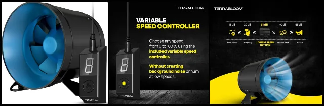
VIVOSUN GROW TENT VENTILATION SYSTEM
Ranked fourth, the VIVOSUN Grow Tent Ventilation System ($139.99) is an all-in-one solution designed to handle cooling and ventilation. It includes a 6-inch inline duct fan with an airflow of 390 CFM and operates at a low noise level of 34 dB. The system also features a premium carbon filter made from Virgin Australian activated charcoal for effective air filtration, along with multi-layer air ducting and stainless steel clamps for durability.
This system would be useful for our vermiculture compost setup, where regulating airflow and temperature is essential for maintaining optimal composting conditions. By effectively managing heat and humidity, it ensures a controlled environment that prevents overheating while also providing fresh air circulation when necessary.
It was ranked fourth because it’s a solid plug-and-play solution that provides basic ventilation needs, although it offers no smart controls or dynamic response to internal temperature shifts. As compared to TerraBloom 6”, it lacks precise speed control and expandability. The TerraBloom, while not smart, can be paired with a thermostat, whereas the VIVOSUN is strictly manual.
PROS FOR THIS VENTILATION DEVICE
- Easy installation with an all-in-one setup.
- Effective air filtration for cleaner air.
- Low noise level at 34 dB.
- Durable materials ensure long-lasting performance.
CONS FOR THIS VENTILATION DEVICE
- Lacks built-in temperature regulation.
- Moderate airflow may not suit larger spaces.
- No remote control or smart features.
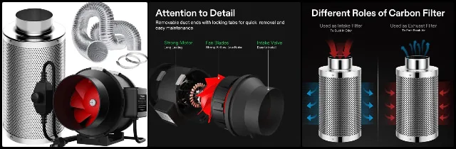
VIVOSUN R8 8 INCH INLINE DUCT VENTILATION FAN
Ranked fifth, the VIVOSUN R8 8 Inch Inline Duct Ventilation Fan ($99.99) is a high-performance fan designed to provide efficient ventilation with an airflow of 720 CFM. Its variable speed controller allows you to adjust airflow to your desired level, making it ideal for customizable ventilation needs. The fan combines axial and centrifugal fan features, enabling it to move large volumes of air quietly & effectively. It’s also easy to install with a compact & lightweight design.
This fan would be helpful for maintaining airflow in the vermiculture system, ensuring optimal ventilation & preventing any excessive heat buildup. Its versatility and adjustable speed offer us control over air circulation, crucial for maintaining a healthy environment for composting.
It was ranked 5th as it offers strong airflow and durability, but over-delivers for a compost system. Although when compared to the VIVOSUN Grow Tent Kit, it lacks the balanced CFM-to-noise ratio and plug-and-play simplicity. The R8’s power is unnecessary and introduces inefficiencies.
PROS FOR THIS VENTILATION DEVICE
- High airflow (720 CFM) for efficient ventilation.
- Quiet operation at 38 dB.
- Adjustable speed control for customized airflow.
- Easy to install with a compact design.
CONS FOR THIS VENTILATION DEVICE
- Larger sizes might be too big for smaller systems.
- Could be overpowered for small spaces.
- May require additional support for installation in confined areas.
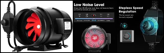
VIVOSUN Z8 8 INCH INLINE DUCT FAN
The VIVOSUN Z8 8 Inch Inline Duct Fan ($99.99) is a powerful ventilation fan designed for optimal air circulation with a flow of 740 CFM and a low noise level of 53 dB. It integrates axial and centrifugal fan features for effective airflow, while its stepless speed controller lets you adjust airflow to your needs. The easy installation process, including a mounting bracket, makes setup quick and simple. This fan is versatile, catering to various ventilation needs in different spaces.
This fan aligns with our vermiculture system by providing the necessary airflow to prevent overheating and regulate humidity levels, ensuring a consistent environment for the composting process.
We ranked it 6th because it shares all the same shortcomings as the R8 but offers no practical improvements, and when compared to the VIVOSUN R8 8”, it provides less airflow without gains in noise, efficiency, or control, making it slightly less optimal overall.
PROS FOR THIS VENTILATION DEVICE
- Strong airflow (740 CFM) for efficient ventilation.
- Adjustable speed control for customized airflow.
- Quiet operation at 53 dB.
- Easy to install with a mounting bracket.
CONS FOR THIS VENTILATION DEVICE
- Noise level of 53 dB may be noticeable in quiet environments.
- A larger size may be overkill for smaller applications.
- May require extra setup for optimal installation in confined spaces.
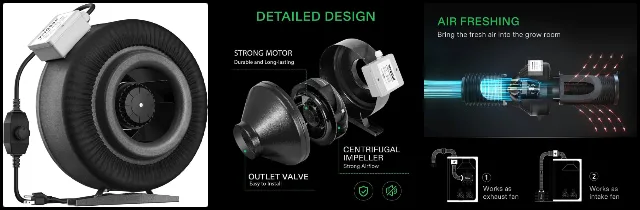
SUNSTREAM 8 INCH INLINE DUCT FAN
The SunStream 8 Inch Inline Duct Fan ($80.99) provides a 720 CFM airflow with low noise at 54 dB, making it ideal for ventilation needs in hydroponic grow tents and other indoor environments. With quality UL components, this fan ensures quiet operation and reduces noise and vibration. Its durable, ceramic-coated construction and permanently lubricated bearings make it maintenance-free. The 5-foot power cord offers flexibility for installation, making it an excellent choice for systems that require reliable ventilation.
In our vermiculture setup, this fan can help manage heat and humidity levels, maintaining an ideal environment for composting and waste breakdown. Its efficiency and durability make it a good fit for keeping the system at optimal conditions without frequent maintenance.
It was ranked seventh because it fails to meet almost all of our critical needs. No smart features, unclear noise levels, and likely overpowered, and when compared to VIVOSUN Z8 8 It lacks verified specs and reliability, making it less trustworthy than even the most basic 8” fans on this list.
PROS FOR THIS VENTILATION DEVICE
- Provides 720 CFM of airflow for efficient ventilation.
- Quiet operation with minimal noise and vibration.
- Maintenance-free with durable ceramic-coated bearings.
- Easy installation with a 5-foot power cord.
CONS FOR THIS VENTILATION DEVICE
- Noise level of 54 dB might be noticeable in quiet environments.
- A larger size may not be ideal for compact spaces.
- Limited warranty period of 12 months.
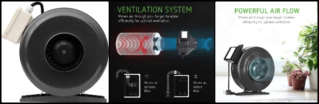
SUMMARY
After thorough research and evaluation of several cooling and ventilation devices, we’ve considered factors such as airflow capacity, noise level, energy efficiency, ease of installation, and durability, all of which are essential for maintaining optimal conditions in a large-scale vermiculture system. Given the need for consistent temperature and humidity control, as well as an environment that minimizes disturbance, we focused on products that combine power with quiet operation and low maintenance.
The AC Infinity CLOUDLINE PRO T6 stands out as the most optimal choice due to its unmatched combination of smart automation, ultra-quiet performance, and precision climate control. With features like a programmable controller for temperature, humidity, and VPD, app integration, and a low noise rating of only 32 dBA, it provides robust and intelligent airflow management ideal for sensitive composting environments. Its EC motor and energy-efficient operation further enhance long-term value and sustainability.
If the AC Infinity CLOUDLINE PRO T6 is unavailable, two excellent alternatives would be the iPower Smart Ventilation Inline Fan and the TerraBloom 6 Inch Quiet Inline Duct Fan. The iPower Smart Ventilation Inline Fan offers smart functionality, including WiFi and voice control, with solid airflow performance (402 CFM) and quiet operation (34 dBA), making it a great option for automated environments, albeit with slightly fewer advanced programming features than our top choice. The TerraBloom Fan, while lacking built-in smart controls, excels in quiet operation and manual precision control through an EC motor and is ideal when smart integration is not required. Its noise level (31 dBA) and durable design make it highly effective for maintaining calm, controlled conditions.
Before making the final purchase, it’s important to check for any newer versions or newer products that may have entered the market. The technology for cooling and ventilation systems is constantly evolving, and new, more efficient devices are released regularly. We should consider all available options at the time of purchase and ensure that we choose the most optimal solution for our vermiculture system, ensuring the best performance, energy efficiency, and overall value.
SENSOR SELECTION FOR CHAMBER GAS REGULATION
Section coming soon…
VERMICULTURE CONTAINER TRANSPORT SOLUTION
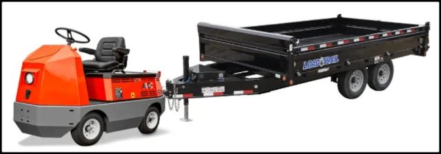
Click to read more about Vermiculture Container Transport Solution
Effective waste management is a cornerstone of sustainable living, and our Vermiculture Eco-toilet Container Transport Solution (click for complete details) ensures that composted materials are efficiently collected and transported with minimal environmental impact. Our detailed research outlines a comprehensive approach to safely and effectively move compost drawers from a vermiculture toilet system to their designated disposal sites.
Transporting compost drawers efficiently and safely is essential for maintaining an effective vermiculture system. This report presents a comprehensive solution for moving heavy compost drawers using an integrated system of an Electric Utility Vehicle (EUV), a utility trailer, and an electric winch. Each component was carefully selected to ensure seamless transport across inclined ramps while optimizing efficiency, safety, and cost-effectiveness. The selection process considered key factors such as towing capacity, power requirements, weight constraints, terrain conditions, and operational efficiency to ensure the system functions reliably under real-world conditions.
To achieve this, we analyzed multiple EUV models based on their power output, towing capacity, and compatibility with the site’s constraints, ultimately selecting the Taylor-Dunn C-425 for its 15,000 lbs towing capacity and cost-effectiveness. For the trailer, a 96” Deckover Dump D8 was chosen to transport all four drawers in a single trip, reducing loading time and labor. Finally, an electric winch was necessary to pull the 1,060 lb drawers onto the trailer, leading to the selection of the BADLAND ZXR 2500 lb. winch, which provides sufficient pulling power with a built-in safety margin.
Beyond equipment selection, the complete report also includes detailed safety guidelines for the operation of the EUV, trailer, and winch, ensuring secure and efficient handling during transportation. These guidelines help mitigate risks associated with heavy lifting, inclined loading, and mechanical operation. By implementing this structured transport system, the process of moving compost drawers becomes safer, faster, and more sustainable. For further details on calculations, selection criteria, and safety protocols, refer to the full report.
RESOURCES
- One Community Resource: Most Sustainable Toilets Research
- Great open source vermiculture site: www.vermicompostingtoilets.net
- Happy D Ranch – Vermiculture Supply
- Commercial Scale Vermicomposting and Earthworm Husbandry
- Manual of On-Farm Vermicomposting
- Five Ways to Harvest Worm Castings
- Free PDF manual comprehensively covering vermiculture and vermicomposting
- Detailed studies on the effectiveness of vermicomposting of human waste
- A company that sells worm farm septic systems that even add greywater
- Here’s a site talking about how vermicomposting toilets don’t traumatize worms
- Open source urine separating toilet seat designs plans we’ll be implementing
- Flush vermiculture toilet working example | more info | completed: followup info
- Humanurehandbook.com featuring the Loveable Loo toilet anyone can set up
- Treehugger.com article: “The Hot Poop on Alternative Toilets”
- Article: “Which Worms Are Best For Composting?”
- Here’s a solar, evaporative, waterless human waste system: The E-Loo
SUMMARY
We went through several designs and even reverse-engineered a successful design before we came up with this one. Our design is inexpensive when compared to similar large-scale designs, easy to build, modifiable, and meets all of our requirements for the Earthbag Village.
FREQUENTLY ANSWERED QUESTIONS
Coming…
WAYS TO CONTRIBUTE TO THE EARTHBAG VILLAGE TOILET DESIGN
SUGGESTIONS | CONSULTING | MEMBERSHIP | OTHER OPTIONS