 One Community
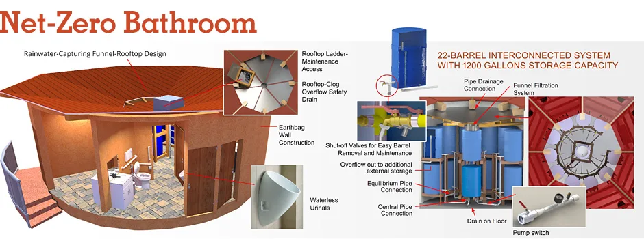
Water Recycling Net-zero Bathroom
As part of the the open source Earthbag Village (Pod 1), we will build and open source project-launch blueprint a rainwater recycling bathroom structure. We call this a “net-zero bathroom” because the water used for this bathroom will be supplied entirely by rainwater collection and sustainable energy infrastructure will make the energy 100% renewable too. This combined with the aEarthbag construction materials makes the entire structure what we call a “net-zero” construction.
This page discusses the water recycling net-zero bathroom with the following sections:
- What is The Water-Recycling Net-Zero Bathroom
- Why Open Source a Water-Recycling Net-Zero Bathroom
- Ways to contribute
- Consultants
- Net-zero Bathroom Design Details
- Final Design
- Cost Analysis
- Net-Zero Bathroom Rainwater Harvesting Design Details
- Estimation of Catchment Area for the Rooftop Rainwater Harvesting System
- Main Components
- Net-Zero Bathroom Stormwater Storage Design
- Initial Net-Zero Bathroom Design and Research
- Resources
- Summary
- FAQ
NOTE: THIS PAGE IS NOT CONSIDERED BY US TO BE A COMPLETE AND USABLE TUTORIAL UNTIL
WE FINISH CONSTRUCTING IT AS PART OF THE EARTHBAG VILLAGE (POD 1) AND ADD TO THIS PAGE
ALL THE VIDEOS AND EXPERIENCE FROM BUILDING AND TESTING IT
IN THE MEANTIME, WE WELCOME YOUR INPUT AND FEEDBACK
RELATED PAGES (click icons for complete pages)
")
![]()

![]()
![]()
![]()
")
")
WHAT IS THE WATER RECYCLING
NET-ZERO BATHROOM
 The Rainwater-Recycling Net-zero Design (top-left in the image below) will be built twice in the South half of the village. It incorporates 100% water self-sufficiency through collection and use of rainwater for flushing and hand washing with traditional septic for county compliance. It will be combined with the Vermiculture Bathroom designs (right in the image below) and the Communal Eco-shower designs (bottom-left of the image below) to sustainably meet the complete bathroom needs for the entire Earthbag Village (Pod 1).

Location of Designs within the Earthbag Village – Click for the Earthbag Village Open Source Hub
WHY OPEN SOURCE A WATER RECYCLING
NET-ZERO BATHROOM
We see the water recycling net-zero bathroom as a realistic and beneficial option for eco-communities, campgrounds, developing countries/areas, and anywhere water resources are scarce and/or people are interested in sustainability. Open sourcing these designs as part of the Earthbag Village (Pod 1) is meant to demonstrate what is possible and provide everything needed for objective evaluation and replication.

Net-zero Bathroom Features Overview Image – Click to Enlarge
WAYS TO CONTRIBUTE TO THE EARTHBAG VILLAGE TOILET AND SHOWER DOME DESIGNS
SUGGESTIONS | CONSULTING | MEMBERSHIP | OTHER OPTIONS
KEY CONSULTANTS TO THE EARTHBAG VILLAGE TOILET AND SHOWER DOME DESIGNS
Alena Thompson: Mechanical Engineer
Beatriz Rocha: Mechanical Engineering Student
Charles Gooley:Web Designer
Diogo Rozada: Civil Engineering Student
Diwei Zhang: Mechanical Engineer
Jorge Antonio Ricardo: Mechanical Engineering Student
Jose Luis Flores: Mechanical Engineer
Julia Meaney: Web and Content Reviewer and Editor
Loza Ayehutsega: Civil Engineer/Assistant Civil Engineer
Matheus Manfredini: Civil Engineering Student specializing in Urban Design
Samuel Soroaster: Permaculturalist, Sustainable Builder, PhD, and founder of Green New World
Zhide Wang: Mechanical Engineer
NET-ZERO BATHROOM DESIGN DETAILS
 The Net-zero Bathroom will be a do-it-yourself replicable structure that demonstrates zero water use beyond what can be collected and stored from rain. It will also integrate a traditional septic and traditional water source to meet county requirements and guarantee function in situations of extreme drought. This will allow others with similar local-level restrictions to duplicate this traditional and eco-option so we can all work together and further validate its effectiveness.
We discuss the design and implementation of this structure with the following sections
- Requirements, Desires, and Features
- Water Use and Collection Calculations
- Water Storage Exploration
- Water Storage Choice
- Facilities Design
- Final Design
- Cost Analysis
- Net-Zero Bathroom Rainwater Harvesting Design Details
- Net-Zero Bathroom Stormwater Storage Design
- Initial Net-Zero Bathroom Design and Research
- Resources
- Summary
- FAQ
REQUIREMENTS, DESIRES, AND FEATURES
The Net-zero Bathroom was designed using the following requirements:
- There shall be 2 Net-zero Bathroom facilities in the Earthbag Village
- The facilities shall comply with the Earthbag Village layout
- Shall be made from commercially available and tested products
- The primary source of water shall be rainfall
- Must provide facilities for 80 people
- 20 Females and 20 Males for each facility x 2 facilities = 80 people total
- Shall comply with municipality septic system laws
- Shall meet a footprint of 28.2 feet
- The roof diameter shall not exceed 34.4 feet
- The water collection system shall be field serviceable
In addition to the above requirements, the following desires were included in the design process:
- Make the design and engineering as simple as possible
- Make the design adaptable to diverse rainfall collection situations
- Use typical construction equipment for construction and maintenance (drills, saws, etc.)
- Make maintenance periodic, not daily or weekly
The finished Net-zero Bathroom designs include the following features:
- Provides rainwater catchment and storage
- Functional even in a semi-arid environment (<1.5″ average rainfall/month)
- Water saving faucet and ultra-high efficiency toilet (UHET)
- Dry urinals with separate collection for males
- Urine-separating toilets for females
- ADA compliance
- Structure is made with Earthbags
- Water storage is provided by 55-gallon barrels in series
- Roof is designed as a reverse camber (funnel) for rain catchment
- Blackwater is collected in a traditional septic system
- Electricity is provided with PV solar
WATER USE AND COLLECTION CALCULATIONS
These Net-zero Bathroom designs are purposed to function effectively in areas of very little rainfall: <1.5″ average rainfall/month. Monthly water needs for 40 people were calculated to be 1274 gallons/month. Structure storage using twenty-two 55-gallon drums was designed to hold an equivalent amount of water: 22 x 55 = 1,210 gallons. Click this link for the open source spreadsheet containing all the calculations and the related data.
Here are the local monthly-rainfall averages we used:

We wanted a design though that would be adaptable to areas of heavier rain and areas with even less rain than ours. To achieve this, we designed the structure with a separate capture area/option and additional external storage. This allows for others to increase, decrease, or eliminate the additional capture area and size the additional storage to meet their specific needs. It also provides the added benefit of much easier roof design. If the roof of this structure by itself were sized to provide sufficient catchment for our needs, it would need to be 243% bigger (see spreadsheet cell B71) to meet these needs on an average month. Larger for low-rainfall months.
For our additional catchment area, we combined the capture from the roof of the structure, half of the nearby Tropical Atrium, and capture from the roof of the adjacent Communal Eco-shower structure. With the above-mentioned monthly rainfall statistics, the following average collection rates were calculated using these equations:
Rainfall per month (in) x Capture area (in2) = Volume of H2O (in3)
231 in3 = 1 US gallon
- Water-collecting roof average: â°Ë† 522 gallons/month
- ½ the Tropical Atrium Roof (60 ft diameter): â°Ë† 548 gallons/month
- 1 Shower Dome roof average: â°Ë† 522 gallons/month
This achieved an average monthly collection total of 1,592 gallons with surplus water going to storage. Here is a chart showing the integration of rainfall for our area and the resulting collection from the additional Tropical Atrium and Communal Eco-shower roofs using the above formulas (spreadsheet):

The next graphic shows use in comparison to collection sources and the net surplus this generates. Storing the surplus is important because there is one month (June – see cells 48C and 48D) where even the combined capture areas won’t provide sufficient water. All other months provide a surplus if average rainfall patterns are maintained. The potential for drought requires the additional capture area and storage, too.

Note that the blue line shows how many gallons we would collect with only the roof. This would not provide sufficient collection from rainfall in our area but it would be sufficient in an area with an average rainfall greater than 3″ per month.
Here’s how that is calculated:
- Area of roof catchment = 96,713 in2
- Needed gallons of water for 40 people = 1275 gallons
- Gallons to inches conversion is 1 US gallon = 231 in3
- 1,275 gallons converts to 294,525 in3 of water needed
- Volume needed (294,525 in3) divided by collection area (96,713 in2) = needed rainfall (3.05″)
Of course, rainfall like this means that the local water table would probably be sufficient such that these types of radical water-saving designs would not be necessary. Still, it is worth noting.
WATER STORAGE EXPLORATION
Water storage both inside and outside are needed for a design like this to manage periods/months of low-average rainfall or drought. Larger catchment and storage areas can also be designed so that additional water can be used for other purposes too. The main challenges with water storage are space requirements and the difficulty of do-it-yourself designs properly sealed and capable of withstanding the pressure of large volumes of water.
In our case, large-scale greywater and rainwater processing and storage were already a part of the larger/complete Earthbag Village design. So this easily solved the issue of external water storage for us. We still needed to explore the options though for internal water storage and external options best to support the Net-zero Bathroom as a more diversely applicable open source and stand-alone design.
Four different options were explored:
- Above Ground Well
- Underground Well
- Small-Capacity Water Barrels
- Large-Capacity Water Barrels
ABOVE-GROUND WELL

The above-ground well option is essentially an uncovered pond built using earth bags.
Pros:
- Can be constructed using earth bags
Cons:
- Difficult to guarantee water seal
- Ongoing loss of water due to evaporation
- Water storage walls cannot be high due to safety concerns (earthquake, improper installation, wear and tear, intense heating and cooling cycles, warping). This means this form of water storage will require larger areas
- Must drain all of stored water to clean
- Possible permitting issues
- Would require ongoing pumping if used as the only water storage source
UNDERGROUND WELL

The underground well option would consist of any underground storage container. The method shown right uses a milk crate-like filling system to prevent well walls from caving inward.
Pros:
- Simple with proper ground excavating equipment
- Many easy option to purchase
- Dependable and durable
Cons:
- May not work in all areas (depending on ground type)
- Difficult/impossible to access depending on depth
- Must utilize a pump to pump the water up to surface
- Must be drained to be cleaned
- Leakage difficult to detect
- Cost
LARGE BARRELS

Large barrels offer many of the same benefits of an underground well with the additional benefits of above-ground placement options.
Pros:
- More space efficient water storage than small barrels
- Can be used as the building’s internal storage option too
- Readily available
- Dependable and durable
Cons:
- Difficult to transport (very large and heavy)
- Difficult to replace if problems occur
SMALL BARRELS

The small barrel option consists of 55-gallon barrels connected together to meet needs.
Pros:
- Readily available & affordable
- Easy to Transport
- Leakage limited to one container
- Easily accessible for leaks and repair
Cons:
- Not the most “eco-friendly” option due to plastic
- Less storage efficiency
- More complex plumbing needed to connect all the barrels
- Would freeze in cold climates if placed above-ground for external storage
WATER STORAGE CHOICE
Small barrels were chosen for internal storage with a tie in to the large-scale greywater and rainwater processing and storage of the Earthbag Village for the external water storage. The primary reasons for choosing the small barrels for the rainwater storage within the structure were:
- Easier and less dangerous for
non-professionals to install - Easily replaceable, transportable, or
repairable if something occurs - Affordable and available almost everywhere
- Barrels are rated for human water use
- Large amounts of different installation literature already exists for particular user needs
FACILITIES DESIGN
Facilities design covers the selection of the bathroom faucets, toilets, and urinals. Our goals for bathroom fixture selection were:
- Minimal water use
- Dependability and effectiveness for public use
- Durability for public use
Below are the results of our research process. Our chosen selections are discussed at the bottom and the calculations above already reflect these choices.
FAUCET OPTIONS
Standard Faucet
- 2.5 gpm
- No pump needed if water barrels are above the faucet
SLOAN OPTIMA: EAF-350 (preferred)
- .35 gpm
- Pump needed for water pressure
- Most sustainable faucet company
- Most sustainable faucet from this company
TOILET OPTIONS

Standard Toilet
Pros:
- Least Expensive (~$95)
- Standard Hook-ups
Cons:
- 1.6 Gallons per flush
Niagara Nano “Stealth Dual Flush” (preferred)
Pros:
- Standard Toilet Fixture
- .6 gal Half Flush Option
- .8 gal Regular Flush
- Most sustainable “standard” toilet we could find
Cons:
- Cost ($220 + shipping)
EcoFlush

Pros:
- Standard Toilet Fixture
- Urine diverting
- .05/.66 gal Low Flush
- http://www.ecovita.net/ekologen.html
Cons:
- Male and female operators must sit on toilet seat for Urine diverter to function correctly
- Cost ($799 + shipping)
Vacuum Toilet
Pros:
- 0.4 gal per flush
- Less likely to get clogged
- http://evac.com/solutions/vacuumcollection/evacoptima5/#building
- http://standard.jetsgroup.com/en/Products/Toilets-and-urinals.aspx
Cons:
- Must have electricity
- Must install vacuum pump (two suggested)
- Most expensive (~$1200)
Toilet Options Overview:


FAUCETS, TOILETS, AND URINALS CHOSEN
- A combination of the Zeroflush Waterless Urinal and Niagara Nano “Stealth Dual Flush” Toilet were selected due to the simplicity of use, installation and lower water usage.
- With water limitations, standard, lower cost toilets were not feasible.
- Notes: Composting or incinerating toilets do not currently meet many municipal standards in the United States, so we didn’t choose those
TOILET WATER AVAILABILITY COMPARISON

FAUCET PLUMBING
- Due to bird or other animals’ feces possibly being in the rain water system from roof, hands will be cleaned from external source (or a bacteria killing filter needs to be involved)
- Water provided is in series with shower facility in village
- Pressure required is 30-60 psi
DRY URINALS
 The Zeroflush Waterless Urinal was the best and most sustainable urinal we could find. Benefits include:
- Odor-barrier liquid made from 100% natural and biodegradable oils
- 100% natural and biodegradable sealant
- Saves around 40,000 gallons of water per urinal per year
- No complex installation is required, just a drainage outlet
- Easy web access to all the product specs, installation, CAD drawings, etc.
- It is a reasonably priced urinal
- Sleek and modern design

OTHER PLUMBING CONSIDERATIONS
- All sewage plumbing must be at a 2% grade
- Sewage plumbing systems must interconnect
- No “T”s suggested in system (only “Y”s)
- Rain barrels must be interconnected for equal distribution
FINAL DESIGN
- Sloped Roof for maximum water capture
- Approx. 8.9 meter diameter roof
- A 22 Barrel interconnected system
- Dry Urinal and Toilets drain to a central septic system
- Faucets receive plumbing from shower facility
- Toilets receive water from barrels
- Facilities similar to common bathrooms
STRUCTURE INTERFACES
- Exterior Structure
- 8 Entrances
- Uses Earthbags 24x12x6
- ~738 Individual bags if continuous bag not used
- (Calculated Using Bag Calculations Spreadsheet)
- Bathroom Furnishings
- 8 unisex bathrooms
- 1 Dry Urinal, 1 Toilet and 1 Faucet
- 8 unisex bathrooms
- Storage Room Access
- 22-Barrel Storage
- Access via Bathroom
- Ladder/Hatch Access
- Hatch Access to Roof
- Overflow Pipe Vertical
- Gutter to outside
- Prevents excessive water on roof
INTERIOR INTERFACES

- Storage Room
- 22-Barrel Rainwater Storage System
- Inner Roof
- Funnels water to central barrel
- Barrel Structure
- Use Load Calculations to determine type of wood and dimensions
- May be a floating shelf or a supported shelf
- Central Pipe Connection
- Filters and circulates rainwater into storage system.
- Equilibrium Pipe Connection
- Common pipe connection to distribute water to barrels equally.
- Pipe Drainage Connection
- All barrels have a spigot and end-cap to drain
- Funnel Filtration System (needs to be researched)
- Mesh screen to prevent large debris build up
- Sediment system to prevent small debris
- Pressure Gauge
- Determines the amount of water available in the storage system
- Drain overflow out
- Overflows excess water in the water storage system
- Drain on Floor
- Floor in storage room sloped 2 degrees
- Drains any spilled water to the outside
VILLAGE INTERFACE

Click to Enlarge
- Sewage (Dry Urinals/Wet Urinals)
- Dry urinal and toilet sewage combined to central sewage location
- Faucet Water
- Procured in series with shower facilities
- Water excess evaporates

MAINTENANCE CONSIDERATIONS
- System Maintenance

- Cleaning/Removing Barrel
- Cleaning Filter
- Cleaning Roof
- Checking Water Levels
SYSTEM MAINTENANCE
- Roof is accessible by internal ladder to clear roof debris
- Toilets can be unclogged and cleaned with conventional means
- Rain barrels are accessible and able to be replaced if necessary or interchanged
- Septic tank will need normal draining and maintenance
CLEANING / REMOVING BARRELS
- Shut off Valve
- Connect hose to spigot or use drainage bucket
- Turn spigot on until the barrel runs dry
- Undo secondary cap over bucket until
runs dry (optional) - Disconnect from overflow (if applicable)
- Remove Barrel
Options (use flexible hose for more maneuverability)
CLEANING FILTER
- Filter needs to be further designed and looked into
CLEANING ROOF
- Use ladder to access roof hatch
- Note: Recommend not cleaning during inclement weather
- Remove leaves and debris from inner roof

CHECK WATER LEVELS
- Inspect water pressure gauge
- Refer to included chart to determine water level based off of water pressure reading
WATER COLLECTION AND STORAGE CALCULATIONS
9/15/20 NOTE: UPDATES COMING FOR THIS SECTION
Water usage was based on:
- Village of 80 adults (40 males and 40 females)
- Bathroom usage
- 5 times per day – 0.05 gallons liquid waste
- 1 time per day – 0.66 gallons solid waste
- Males use dry urinal when urinating
- Annual rainfall statistics for semi-arid climate
- Roof diameter of bathrooms was initially assumed to be 29.3 ft (x2 structures)
- Faucet uses 0.035 gallons/min
- It takes an average of 25 seconds to wash hands
- Given:
- Water collection diameter of Atrium – 60 ft
- Water collection diameter of shower facilities – 29.3 ft (x2 structures)
WATER USAGE CALCULATIONS
9/15/20 NOTE: UPDATES COMING FOR THIS SECTION
- Assumed 500 gallons of water were available to start
- Chose 2,400 gallons as desired tank capacity
36.4 Gallons Flushing per day
1128.4 Gallons Flushing per month (31 days)
4.7 Gallons sink/day
145.7 Gallons sink/month
- Adding all of the collection areas together
- Atrium: pi*(60ft/2)^2
- Shower: pi*(29.3ft/2)^2 * 2 structures
- Bathroom: pi*(29.3ft/2)^2 * 2 structures
- Total Area = 5,525 ft^2 or 795,522 in^2
- Month Rain Captured = Total Area * inches-of-rain in calendar month
- Monthly Net Gallons = Water in Storage/Previous Month Net + Month Rain Captured – toilet use-sink use
BARREL SIZING
The barrel sizing was based on:
- Standard small barrels can store 55 gallons
- Maximum volume of water that needs to be stored is 1,275 gallons
- 22 barrels = 1,210 gallons of storage
- 2-Tiered barrel configuration was chosen to save space
INNER STRUCTURE
The inner structure was sized based on:
- Diameter of barrels/size of barrel stands
- Minimum maintenance access
- Number of barrels needed (22) and configuration of barrels
Additional Design Considerations:
- Doorway entrance
- Funneling central structure
- Ladder and hatch access
Resulting Diameter: 156″
 ROOF DESIGN
The roof design was based on:
- Water collection area
- Strength of Earthbag structure
- Retainment of water after capture
- Water should run to the center and not to the outside edge
- Trade study was done with gutters and it was found that they are less efficient than a central funnel
- Manufacturability
- Maintenance & Accessibility
Final Design:
- 8 identical steel polygon panels assembled in an inverted roof for exterior
- 6 identical steel polygon panels assembled in an inverted roof for interior with hatch access

OUTER STRUCTURE
The exterior structure was designed to:
- Accommodate Roof Size
- Adequately support panels for water capture and maintenance
- Interior water storage needs
- Handicap access doorways and toilets
- Number of bathrooms with toilet fixtures
- Earthbag strength properties
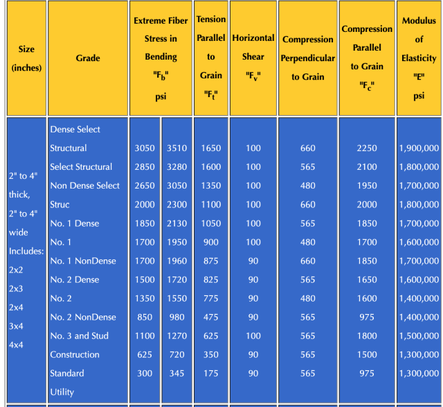
BARREL SUPPORT STRUCTURE
- Needs to support 55Ga*8.2 lbs/Ga + 25 lbs (barrel)
- Deflect only 1/400 (Max Deflection Ratio) of the woods total length
- Equation for Max Deflection for Simply Supported Beam
- Deflection=Load*Length^3/(48*E*I)
- Deflection/Length=Load*Length^2/(48*E*I)=Max Deflection Ratio
- Load=((48*E*I)/Length^2)*Max Deflection Ratio
- Where I is second moment of inertia for a rectangular beam, E is the Modulus of Elasticity for structural wood, Length is the long length of the beam, and Load is the weight of the barrel
- Has four 1×4 primary horizontal wooden beams to support each barrel
- Vertical 4 x 4 beams tie to the ground
- Same structure for central structure
WATER BARREL FEATURES
Each Barrel is required to include:
- Top hole vents to prevent suction
- A connection to an overflow barrel
- Does not need to be included in every barrel if barrels are interconnected
- A spigot to drain
- A bottom tap to drain and clean
- Shut off valve to system

WATER BARREL INTEGRATION
- All top-tier barrels are directly connected to the barrel immediately beneath them
- There is a shutoff valve between the top and bottom tier
- All bottom tier barrels are connected to the adjacent barrel (except at the ends)
- Each barrel has a shut off prior to adjacent union
- Between every other barrel union, there is a connection to the central barrel
- Top barrels and bottom barrels can be removed from the system between shut off valves
- Example: 3 Barrels are removed in the system but all barrels remain tied without leakage. Barrels can additionally be moved and re-positioned.
ADDITIONAL FEATURES

Pressure Gauge
- Measuring the water level can be done with a pressure gauge
- With a known PSI, the water height can be estimated
- A pressure switch can activate an external pump whenever water is low
- System will draw water from external sources anytime water levels reach ¼ filled
Drainage Pump
- A small pump either manual or electric can be used to siphon water from the spigot of a defective barrel to another barrel

WATER BOOSTER (IF APPLICABLE)
For water that is stored above toilets:
- The water storage system will serve as the a universal water storage tank for all toilets
- Water is simply gravity fed to toilets
For water that is stored below toilets:
- Water pressure booster/pump is required to pump water up to toilets
COST ANALYSIS
| Fixtures | $10,000 |
| Rain Barrels | $1,600 |
| Wood1 | $1,300 |
| Roof & Water Sealing | $300 |
| Structure2 | $5,000 |
| Plumbing3 | $3,000 |
| X~1.3 fudge factor | |
| Total Cost | $22,000 |
Notes
1Storm Rated Exterior Wood
2With finished walls and floor
3Sewage Output certified by professional
Communal-use rainwater recycling bathrooms will be within a short walk for all residents of the South, East and West parts of the village (see the Pod 1 layout). These bathrooms will integrate traditional septic for all toilets. The rainwater collection cistern in the center will capture and store enough water to meet all of the hand-washing and toilet-flushing.

The One Community Earthbag Village Communal Shower and Net-Zero Bathroom | Concept Render ” View Looking Northeast – Click to enlarge

The One Community Earthbag Village Communal Shower and Net-Zero Bathroom | Concept Render ” View Looking Northeast – Click to enlarge

The One Community Earthbag Village Communal Shower and Net-Zero Bathroom | Concept Render ” View Looking South – Click to enlarge

The One Community Earthbag Village Communal Shower and Net-Zero Bathroom | Concept Render ” Cutaway View
NET-ZERO BATHROOM ROOFTOP RAINWATER HARVESTING DESIGN DETAILS
Our net-zero bathroom rooftop rainwater harvesting system is a sustainable water management strategy that involves capturing rainwater from rooftops and using it to supply non-potable water needs in a bathroom. This system can help to reduce reliance on traditional water sources, save energy and costs, and promote environmental sustainability. The design of our system requires careful consideration of factors such as rainfall patterns, roof area, storage capacity, and demand for non-potable water in the bathroom, and may involve the use of various components such as gutters, downspouts, filters, pumps, and storage tanks.
‹â€¹We discuss the design and implementation of this system with the following sections.
- Estimation of Catchment Area for the Rooftop Rainwater Harvesting System
- Main Components
ESTIMATION OF CATCHMENT AREA FOR THE ROOFTOP RAINWATER HARVESTING SYSTEM
Water collected from roof top catchment is relatively clean and can be used as potable water for sink faucets with filtration and disinfection. To design a rainwater harvesting system, we need to consider rainfall supply, water demand, catchment area, and storage capacity. Rainfall supply mainly depends on local monthly rainfall rates while water demand depends on the number of occupants, fixtures (toilets, showers, and faucets) water consumption rating, and the average usage patterns of fixtures. The catchment area can be obtained from calculating both rainfall supply and water demand. The reason for determining the storage capacity is to find the minimum storage capacity that guarantees a zero-water volume never happens.
RAINFALL SUPPLY

High Desert Utah Local Monthly Rainfall – Click for source
In this project, we use the monthly rainfall of a particular area to determine the rainfall supply. Most local monthly rainfall data can be found online by searching a target location’s name followed by ‘Climate Normals’. The collected local monthly rainfall data for high desert Utah is prepared in a sheet format as shown below.
Local monthly rain data is then used to calculate the total annual average rainfall and averaged monthly rainfall. The total annual average rainfall is the summation of the average monthly rainfalls of twelve months. The averaged monthly rainfall is equal to the total annual average rainfall divided by twelve.
When calculating the water supply, roof efficiency must be taken into consideration. Depending on the porosity and absorption of a roof’s material there can be losses in the amount of rainfall that gets collected. A table of roof efficiency based on material is shown below.

Roof Efficiency Based on the Roof Material
In this case, we assume the roof efficiency is equal to 0.9. The input in the calculation table is shown below.

Roof Efficiency Input – Click for source
The effective rainfall takes into consideration losses during catchment and therefore, it is what is used to calculate the final volume of water that can be effectively stored in the water tank. It is equal to the actual rainfall multiplied by the roof efficiency.
The table below shows the results of the total annual average rainfall, the total annual rainfall supply, the averaged monthly rainfall, and the averaged monthly rainfall supply.

Total, Effective, and Averaged Rainfall – Click for source
The yearly rainfall supply can be calculated with the following formula:
Yearly rainfall supply = Total annual average x rainfall Catchment area x Roof efficiency
Based on this formula, we can estimate the catchment area as long as we determine the needed yearly rainfall supply. We want the annual rainfall supply to match annual water demand in order to ensure a sufficient amount of water is harvested for use. In the next section we are going to determine the water demand.
WATER DEMAND
Water demand is dependent upon the number of occupants, the water consumption of the fixtures, and the usage patterns of fixtures. In this project, we assume that one installment of the rooftop rainfall harvesting system supplies 50 occupants.

Number of Occupants of One Installed Rooftop Rainfall Harvesting System – Click for source
The potential fixtures using the harvested water include toilets, showers, and faucets. In this case, we assume the faucets are the only fixture that is supplied by the rainwater harvested from the rooftop. This water is relatively clean and can be converted to be potable with less expensive filtration and disinfection. The average manufacturing rating and usage pattern of different fixtures are shown in the following table, where Lpf is liters per fixture; Lpm is liters per minute; and Lpd is liters per day.

Average Manufacturer’s Rating and Average Usage Pattern of Fixtures – Click for source
As stated previously, only faucet water usage is considered in this case. From the water demand of all faucet fixtures per person per day, we can deduce the total daily demand of all occupants, monthly water demand of all occupants, and yearly water demand of all occupants. The results are shown in the following table.

Water Demand – Click for source
CATCHMENT AREA
A catchment area is an area of land where rainwater flows into a specific water body such as a lake, river, or ocean. The size and shape of the catchment area determines how much water will be collected and the rate at which it will flow into the water body.
We want the yearly rainfall supply to match the yearly water demand such that,
Yearly rainfall supply = Yearly water demand
This is ideal in the instance that only the minimum yearly supply is needed without redundancy. Combining the formula introduced in the section of rainfall supply, we derive the formula for the catchment area such that,
Catchment area = Yearly water demand / total annual average rainfall x roof coefficient
The results of the rooftop catchment area are shown below.

Calculated Required Catchment Area – Click for source
STORAGE CAPACITY
A water tank size being equivalent to the yearly rainfall supply guarantees a sufficient water storage capacity. However, this method would result in an impractically large water tank. Determining the optimal storage capacity design happens through multiple trial and error processes and can not be found simply with one single input and output process. The water tank should be large enough to ensure that it never reaches a zero volume. In our case, we want to find a minimum storage capacity to prevent zero volume storage at the end of each month based on the monthly rainfall supply and the monthly water demand.
Firstly, we assume a storage capacity such that:

Assumed Storage Capacity – Click for source
This input of assumed storage capacity needs to be adjusted to balance the supply and demand of the rainwater harvesting system. By adjusting assumed storage capacity, we aim to ensure all the month end volumes from years 1 to 4 in the “Storage Performance” are larger than zero. The first attempt of the assumed storage capacity could be the summation of the largest three demand months. The largest three demand months are found in the “Demand” column of the table below.

Storage Performance – Click for source
Then, check if any Month End Volume is equal to zero in the Years 1 through 4 columns of the table.
- If the answer is “No”, this means your storage capacity is sufficient or oversized. Try a smaller assumed storage capacity number with small decrements until the minimum storage performance barely exceeds zero.
- If the answer is “Yes”, this means your storage capacity is too small. Try a larger assumed storage capacity number as your input with small increments until the minimum storage performance barely exceeds zero.
Keep reiterating the previous procedures until an absolute minimum is found that balances the supply and demand of the rainwater harvesting system.

Optimized Storage Capacity – Click for source
MAIN COMPONENTS
There are many components in a rainwater harvesting system. Each component is organized into three essential categories based on its function. The three categories of components are collection and pre-filtration, storage, and distribution.

Overview of Rooftop Rainwater Harvesting System Design
The category of collection and pre-filtration includes components with functions of capturing rainwater from the rooftop, diverting the rainwater, removing large debris, and conveying the rainwater. The category of storage includes a selection of water tanks, inlets, outlets, overflows, and air vents. The distribution category includes the water pump, water pressurization, final filtration, and disinfection functions.
COLLECTION AND PRE-FILTRATION
Essential components in the collection and pre-filtration category include the roof, gutter, downspout filters, and conveyance pipes. These components are designed to effectively collect rooftop rainwater and convey it to the storage.
ROOF
For non-potable water that is typically collected from ground surfaces and sometimes excess rooftop water, almost any hard or impervious roof surface material can be used. For potable water, however, slick catchment surfaces are desired. The roof materials need to be nontoxic. The following table shows some regulation of the roof material for the rainwater harvesting.

North America Regulatory and Standard-Started Requirements of Roofing Material for Potable and Non-Potable Systems – Click for source
Some materials used for the roof of rainwater harvesting are factory-coated enameled steel, sheet steel coated with aluminum-zinc alloy, galvanized method, terracotta tiles, concrete tiles, cement tiles, glazed tiles, and slate tiles. Wood or cedar shake roofing are not recommended to be used for collection water. In selecting roof material for the rainwater harvesting, it is worth to pay attention to the following:
- Non Toxic sealant or grout are required.
- The concrete should not contain fly ash.
- Water exposure to rubber gaskets should be avoided.
- All coating needs to be nontoxic and meet NSF 61.
PRE-FILTRATION
The goal of pre-filtration is to reduce the debris in the rainwater storage. Rodent feces, animal remains, dust, leaves, sticks, and other debris are potential contaminants that come from the roof or gutter into the water storage tanks. Most debris can be kept out of the storage by using screens and pre-filters, which is what our design uses.
First flush diverters, devices for capturing and diverting the most contaminated water during initial rainfall, are not included in this project. Even though it is a popular device in the rainwater harvesting system, requirement of frequent maintenance and insignificant improvement of water quality make it less attractive.
GUTTERS AND DOWNSPOUTS
In the rainwater harvesting system, the gutters capture runoff from the roof and redirect flow to the downspouts. The system for potable water should not use gutters made of copper, zinc, or organic material such as wood, ceder, or bamboo. Here are some guidelines for selection and installation of gutters:
- Gutters need to be at least 5 inches wide.
- Select gutters made from galvanized steel or aluminum.
- A rounded-bottom helps to decrease debris buildup.
- Slope sectional gutters 1/16 inch per 1 foot of gutter to enhance flow.
- Slope seamless gutter 1/16 inch per 10 feet.
- Use expansion joints at connections for straight runs exceeding 40 feet.
- Keep the front of the gutter ½ inch lower than the back.
- Provide gutter hangers at least every 3 feet (every foot in areas with heavy snow load).
- Apply external gutter hangers where possible.
- Select elbows with 45-, 60-, 75-, or 90-degrees, as needed.
SIZING OF GUTTERS
It is recommended to use the Uniform Plumbing Code to size gutters and downspouts. To determine the size of gutters, we need to know rainfall intensity for one hour, gutter slope, and catchment area. Then, using those three variables, select the gutter size based on the table shown below. Reversely, we can adjust the gutter slope by using different sizes of the gutter with given catchment areas and rainfall intensities. In some Plumbing Codes the flow rate serves as a combination of the rainfall intensity, and the catchment area is used for sizing gutters and downspouts.

Sizing of Gutters – Click for source
GUTTER DEBRIS SCREEN
Adding a screen cover to the gutters provides initial filtration to the rainwater harvesting system and prevents leaves, twigs, and other contaminants from entering. The selected aluminum gutter guard shown in the figure below has been attached already and only filters larger debris. Regular maintenance is required to keep effective rainwater capturing and reduce water contamination.

Gutters with Guards Used to Capture Runoff From the Roof of the Tropical Atrium – Click for product
SIZING OF DOWNSPOUTS
Downspouts refer to vertical pipes that facilitate the controlled flow of excess water from a gutter to the ground, safely directing water away from a building and towards a drainage area. Sizing of downspouts is similar to the sizing of gutters, however, slope is not applicable for the downspouts design. Knowing the rainfall intensity and catchment area, we can determine the size of downspouts using the table shown below. The size refers to the diameter of pipes.

Sizing Roof Drain, Leaders, and Vertical Rainwater Piping – Click for source
DOWNSPOUT FILTERS
The downspout filters are mostly installed vertically inline of the downspout. It is an easily installed and inexpensive pre-filtration device. The downside is that this filter needs to be mounted close to the roof, so climbing a ladder is inevitable for cleaning it.

Downspout Filter – Click for product
STORAGE CONTAINERS
The storage containers are one of the most important components of the rainwater harvesting system as they are responsible for keeping the water safe and secure. Sedimentation and biofilm are the main contaminants that can occur in the water storage containers. To reduce the impact of those contaminations, the following design principles should be kept in mind:
- Keep a minimum water level in the tank that is above the inlet level.
- Reduce the flow energy at the inlet by splitting the flow into two and pointing the pipe upward. Keep the inlet above the sludge layer to avoid water flow disturbing the settled sedimentation at the bottom of the container. The recommended minimum height of the inlet to the tank is 4-8 inches.
- Place the inlet pipe at the center of the water container.
BARRELS WATER STORAGE SYSTEM THEORY AND ANALYSIS
The barrels water storage system functions to collect and store rainwater for future use. The system involves the use of large barrels for storing captured rainwater that falls on rooftops. This method has become increasingly popular in areas with limited access to water or where water is scarce. The theory behind the system involves understanding the principles of hydrology, water conservation, and storage capacity, while the analysis involves evaluating factors such as the amount of rainfall, the size and number of barrels needed, and the potential uses for the stored water.
THEORY BACKGROUND
The branched and looped multiple reservoir system is shown in the following figure.

Branched & Looped Multiple Reservoir System as a Part of the Barrels Storage Network – Click for source
In general, when we deal with any type of water distribution system, nodes 0, 1, 2, 3, 4, 5, 6, 7, and 8 can be used to represent drain inlets, pipes junctions, or reservoirs. In our case, the water storage system consists of multiple barrels: we use nodes 0, 1, 4, 5, 6, and 7 to indicate barrels, where node 0 is the central upper barrel, node 1 is the central lower barrel, and nodes 4, 5, 6, and 7 are the surrounding lower barrels. Meanwhile, nodes 2 and 3 represent 4-way pipe fittings which connect barrels and each other.
To satisfy the conservation of mass, we have
∘ Qi = qj
Where Qi is the discharge of pipe i meeting at node j, and qj is nodal withdrawal at node j. Conservation of energy with consideration of pump head and known energy is
∘ Ki Qin – ∘hpi = ÃŽEFGN
Where EFGN is the difference in energy between the two fixed grade nodes (FGN). Pump head hp expressed by a common equations for approximating a pump curve are
hp = AQ2 + BQ + Hc ,
Where A, B, and C are coefficients and hc is the maximum or cutoff head. For a closed loop, without considering the pump head, the algebraic sum of the head loss must be equal to zero, then we have
∘ Ki Qin = 0.
Without considering the minor loss (elbow, bend head loss), based on the Darcy-Weisbach equation
hL = 8fLQ2 / π2gD5
we have
Ki = 8fiLi / π2gDi5
and
n = 2
where Li is the length of pipe i, g is the gravitational acceleration coefficient, Di is the diameter of the pipe i, and fi is friction factor which is expressed as for both turbulent flow and laminar flow
f = {(648 / R) + 9.5 [ln(ÃŽµ / 3.7D + 5.74 / R0.9) – (2500 / R)6]-16}0.125
where દ is the average height of roughness projection of the pipe wall. R is the Reynolds number
R = 4Q / πvD,
with kinematic viscosity
v = 1.792 Ô 10-6[1 + (T / 25)1.165]-1
as a function of the water temperature T.
SYSTEM OF EQUATIONS
Applying the mass and the energy conservation on the junctions and loops of the water distribution system shown in the last figure, we have
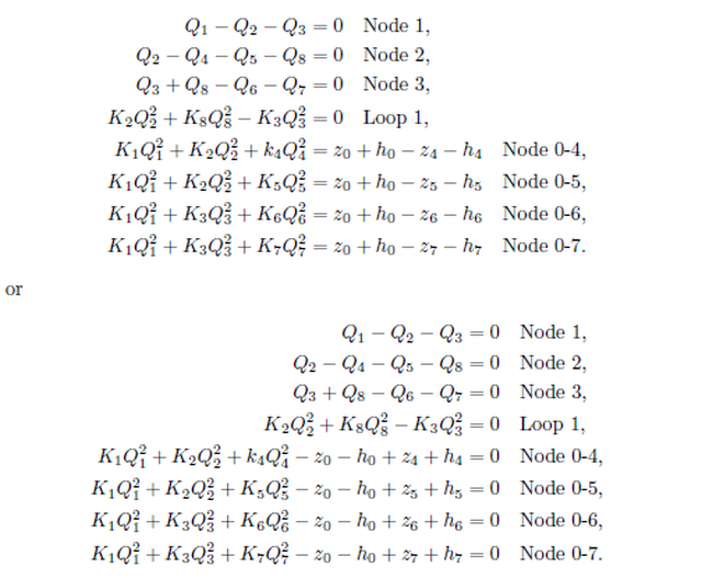
Where Zi is the height of bottom of the ith barrel and hi is the elevation of the water in the ith barrel relative to its bottom.
The water distribution is expressed with eight equations, eight unknowns could be calculated with given parameters. Normally, flow rate of each pipe are unknowns.
NEWTON-RAPHSON MODEL
The system equations are a set of nonlinear equations. The Hardy-Cross method is usually used for hand calculation. For more complex networks, numerical methods need to be applied. The Newton-Raphson method is generally applied for solving a system of nonlinear equations. For the case where all flow rates are unknown, the system of equations is written in the following form.
F1 (Q1 , , Q8) = 0,
F2 (Q1 , , Q8) = 0,
F8 (Q1 , , Q8) = 0.
Which in a general form is
F(x) = 0.
Then, the Newton-Raphson method is expressed as

Jacobian Matrix – Click to Enlarge
The nonlinearity of in the friction factor f (Q) is not involved in the Newton-Raphson method which is updated after iterations with a new flow rate. This idea comes from the Hardy-Cross method.
PARAMETERS
The parameters of pipes (i) and nodes (j), length (Li), diameter (Di), elevation of node(Zj), and the average height of roughness projection of node (hj) are listed in the table below.
This theory and analysis was developed with reference to the “Essential Rainwater Harvesting: A Guide To Home-scale System Design” by Rob and Michelle Avis, “Design of Water Supply Pipe Networks” by Prabhata K. Swamee and Ashok K. Sharma, and “Water Distribution System Handbook” by Larry Mays.
TYPES OF STORAGE TANKS
There are 5 main types of storage tanks that can be considered for the water storage design: precast concrete tank, ferrocement tank, steel tank (stainless steel tank), fiberglass tank, and polyethylene and polypropylene tank. Below are descriptions of each of these types of tanks.
PRECAST CONCRETE TANKS:
Precast concrete tanks are constructed by manufacturers and delivered to their destination in one piece using heavy equipment. These types of tanks are long lasting (30+ years), add minerals such as calcium carbonate to the water, have marginal impact on the water’s taste, and are suitable for buried application. However, they are the most expensive storage tank option. Their heavy weight also makes them difficult to deliver from long distances.
FERROCEMENT TANKS:
Ferrocement tanks are built first by constructing a frame that then has a concrete mixture sprayed onto it, forming the tank structure. It shares all advantages of the precast concrete tanks but additionally, ferrocement tanks are able to neutralize the pH of stored water. They are a fully customizable tank which is optimal for sites with constrained space. However, a skilled constructor is required for building one, and they are not movable once built.
STEEL TANKS:
Steel tanks are long lasting (20-30 years) and have a reasonable cost. However, they are not allowed to connect to metal piping as corrosion may occur at the interface between the two metals. They are not acceptable for uses below grade.
Stainless steel tanks are also categorized as steel tanks. These are even longer lasting (100+ years) than steel tanks and are able to resist corrosion. However, they are expensive and also cannot be applied below grade.
FIBERGLASS TANKS:
Fiberglass tanks are a very lightweight tank option and are consequently easy to transport. They have good corrosion resistance and are able to be used below grade. However, fiberglass tanks are not cost effective for small sizes (1000 gallons).
POLYETHYLENE AND POLYPROPYLENE TANKS:
Small and medium plastic tanks are low-cost and potable. They have a medium length lifespan (15+ years) and come in many shapes and sizes. They have much less of an impact on water taste compared to concrete and steel tanks.
TANK COMPONENTS
It is necessary to outfit a water tank with an inlet, an outlet, an overflow outlet, an air vent, and a manway inspection port. In this section, we will go through the system following water flow.
INLET
The function of the inlet is to guide the water into the container. Its configuration should minimize stirring to avoid disturbing any settled contamination. The inlet pipe runs through the center of the water tank with a return bend pipe that redirects the water flow upward. The inlet typically sits 4-8 inches above the bottom of the water tank.

Water Tank Inlet Pipe Schematic Diagram
OUTLET
To minimize contamination, the pickup for the tank outlet should not take water from the surface or directly off the bottom. The best quality water is usually found below the water surface where biofilm or settled contamination is not present. To pick up water from a region with the most clean water you must use a floating pick-up with a mesh screen or filter, specialized for water being used as potable water.

Floating Pickup With a Mesh Screen or Filter Used For Potable Water

Floating Pickup With Filter Connecting the Tank Outlet to a Flexible Pipe

Check Valve, Faucet, Flexible Coupler, Pipes, and Fittings of the Storage Container Outlet
OVERFLOW OUTLET
Overflow outlets are used to release extra water when tanks are filled to their maximum capacity. To ensure the outlet flow rate matches the inlet flow rate, pipes for overflow outlets should be at least the same size as the inlet.
The overflow outlet should avoid the siphoning action that may inadvertently empty the tank. An air gap is also needed to prevent backflow and a mesh screen should be equipped right below the air gap to prevent the entry of rodents or insects into the overflow outlet.

Overflow Outlet with Air Gap to Avoid Backflow
MANWAY
A manway is a hatch that allows entry for completing tank maintenance. The selected plastic tank has a 16-inch diameter manway port. Installation of inlet, outlet, and cleaning settled contamination usually call for a person to enter the manway.

Manway with a Plastic Lid
AIR VENT
Air vents allow air to enter and leave the tank in order to keep the pressure equivalent to the atmosphere as the water level in the tank changes. A typical air vent can be built from pipes, elbows, and fittings, and is mounted on the lid of the manway. A mesh screen should be equipped on its exterior opening to prevent entry of rodents or insects.

Exploded View of The Air Vent

Air Vent Mounted on the Lid of the Water Tank
CONNECTION OF MULTIPLE TANKS
For cases that call for more than one tank, tanks need to be connected together. Multiple tanks may be required when a single tank capacity does not provide enough water storage, land configuration may not support a single large tank, or a certain portability of water tank is desired.
There are two main ways to configure and connect multiple tanks: parallel or in a series. In a parallel configuration, water tanks share the same water level, requiring only one overflow outlet for all tanks. Since there is the same level of water among tanks, however, the parallel configuration is not suitable for water tanks seated at different elevations. Connecting water tanks in a series cascades water flow from the first tank to the second and so forth. Each water tank requires an individually equipped overflow outlet. In a series, water tanks are allowed to sit at different elevations. Water quality increases through each overflowing tank since a little sediment is always captured by the previous water tank. Extra bypass piping is needed to ensure a single water pump is able to extract water from all tanks.
Considering simpleness and water tanks that are placed on a flat ground, a parallel configuration is chosen for multiple tanks. There are two examples: two tanks in parallel and four tanks in parallel. A check valve is equipped at the outlet of each tank to enable the isolation of a tank when others are under maintenance, or when the tank is in transportation with water. Flexible couplings are used to endow compliance of the multiple tanks system since the placement of tanks and uneven ground are inevitable.

Layout of Two Water Tanks Connected in Parallel

Layout of Four Water Tanks Connected in Parallel

Piping, Fitting, and Check Valves of Four Tanks Connected in Parallel
DISTRIBUTION SYSTEM
The distribution system supplies the water from storage containers to end uses such as toilet flushing, irrigation, and showering. Water pumps are used to convey water along certain distances and heights to various destinations. Integrating a pressure tank downstream of the water pump pressurizes water, leading to a more consistent water pump functioning under inconsistent water uses and an elongated lifespan of the pump. Different end uses require different water quality; water filtration and disinfection systems purify water to satisfy desired water quality.
WATER PUMP
To select a water pump, the total dynamic head (TDH) from the storage container to the end uses fixtures need to be calculated. The total dynamic head is as follows:
TDH = static head + pressure head + friction loss
Where the static head is determined by the vertical distance from the outlet to the water tank to the end (fixtures such as shower heads and faucets); Pressure head is given by the required emitter/shower head pressure. The water tank under the shower room is an additional water storage container to the barrels in the net-zero bathroom. There is no strict requirement to the emitter pressure. Friction loss considers pressure loss along pipes, through elbows, or fittings. The conversion between pressure square feet and water head is shown in the following charts.
 and water head (ft) - Click for source")
Conversions Between Pressure Square Inch (PSI) & Water Head (ft) – Click for source
Friction losses of pipes, elbows, fittings, and valves can be calculated theoretically or experimentally. They are dynamic pressure drops that depend on the flow rate and geometry. In practice, there is no need to calculate friction losses of each component based on the fluid dynamics. We apply the equivalent length pipe method to determine the pressure drop of friction losses. Based on the flow rate, geometry, and dimension of the plumbing parts, friction losses can be found simply from the equivalent length pipe method tables. Equivalent length of friction losses of pipes, elbows, fittings, and valves can be found in the following tables.

Table of Friction Losses of PVC Pipes Under Different Flow Rates – Click for source

Table of Friction Losses of Elbows, Fittings, and Pipes of Equivalent Length – Click for source
Since the pump’s location allows the water to be fed into the inlet hosing of the pump with just gravity, it is unnecessary to consider the pump’s suction capability. The suction head is not calculated for the pump of the water tank under the shower room.
Selected pumps need to provide a sufficient water flow rate to ensure end use fixtures have adequate water. The rooftop rainwater harvesting system, including the tropical atrium and water tank under the shower room, is a set of redundant facilities to the RWH system in the net-zero bathroom. Barrels in the net-zero bathroom play the role of a buffer between the large underground water tank and the end use fixtures. Underground water gets pumped to the barrels before going to the restroom fixtures, rather than being pumped directly to the fixtures themselves. This allows for the immersible water pump to avoid being frequently turned on and off. Further, if there are multiple fixtures being used at one time, the pump may not be able to supply enough water in a short period of time. Essentially, the pump continues to fill the barrels with water from the large underground storage tank so that restroom fixtures have a sufficient, reliable water supply. Thus, there is no strict restriction of the flow rate applied upon the pump.

Pump, Filtration, and UV Disinfection System
PRESSURIZATION
The water pump is usually driven by an electric motor. It is better to run all electric equipment in a continuous working condition rather than intermittently. The water end uses, however, such as handwashing, showering, and toilet flushing tend to cause intermittent water flow. To keep a less discontinuous water supplying condition, a pressure tank is usually mounted downstream of the water pump to add a buffer into the water distribution system.
There are three main types of pressure tanks: air-over-water pressure tanks, diaphragm pressure tanks, and bladder pressure tanks.
The air-over-water tank is a simple and old pressure tank where both un-pressurized water and pressurized water are kept in the same chamber without any separation. Air will dissolve in the water and more water is filled into the pressure tank that neutralizes the pressure tank. Draining water from the filled pressure tank after a certain period rejuvenates the capacity of the pressure tank.
Diaphragm and bladder pressure tanks are more modern designs. In these pressure tanks, water and air are separated into two chambers without contact. Diaphragm pressure tanks use a rubber diaphragm attached to the sides of the chamber to separate the water from the air. The rubber diaphragm tends to fail after a certain amount of use because of the limited life span of the rubber. Bladder pressure tanks are similar to the diaphragm pressure tanks but typically have a longer lifespan.

Pressure Tank

Bladder Pressure Tank Graphic – Click for Source

Lowe’s A. 0. Smith 52-Gallon Vertical Pressure Tank – Click for Source

Pressure Tank Dimensions Graphic

Graphic of Pressure Tank Location
FILTRATION AND DISINFECTION
Regulations may apply to the rainwater harvesting system for drinking water. The Environmental Protection Agency (EPA) along with other governmental agencies have authority to regulate water for public drinking water systems.
The runoff water quality is most affected by the catchment area, conveyance system, and storage components. Microbial and viral contaminants are found in the catchment area as a result of various interactions with animals, such as birds that sit on the roof. There are also chemical contaminants found in many rainwater harvesting systems.
A frequent test of the water quality for non-public drinking water systems is requested at least once a year based on regulations. Results of testing need to meet minimum federal and state standards. An EPA national secondary water standard is shown below.

EPA National Secondary Water Standards (2009) – Click for source
Harvested rainwater from a roof is technically surface water, which is considered more likely to be contaminated than ground or well water by the EPA. As a result, there are more strict treatment requirements for converting surface water to potable water in order to minimize the risk of negatively impacting the health of individuals. Examples of potable water treatments that remove or reduce contamination include screening, sedimentation, filtration, ultraviolet light exposure, chlorination, and anti-corrosion additives in sequence. These are briefly discussed below.
- Flocculation/Sedimentation uses additives to promote coagulation of small particles into larger particles that make them sediment.
- Filtration removes all particles such clays, silts, natural organic matter, iron, and manganese from the water.
- Ion exchange processes are used to remove inorganic contaminants such as arsenic, chromium, excess fluoride, nitrates, radium, and uranium, and to treat hard water.
- Chlorination can kill most microorganisms and viruses. Only chlorine devices certified by ANSI/NSF Standard 60 should be used. The chlorination controls the contamination of the water distribution system in the long term after being employed.
- Ozonation disinfection introduces ozone into the water to inactivate cryptosporidium, bacteria, and other microorganisms.
- Ultraviolet Light certified by ANSI/NSF Standard 55 or 60 is used to control against pathogens. Filtration should be applied before an ultraviolet light treatment to avoid suspended particles blocking ultraviolet light.
- Activated Carbon processes attract organic contaminants to the surface. A carbon filter is not a primary sanitation device and should be used in addition to an effective sanitation method. The carbon filter should also be placed upstream of a chlorinator and UV system, unless it is desired to purposefully remove chlorine.
A typical treatment train for a rainwater harvesting potable water system includes a 3-5 micron level filter, a 0.5-1.0 micron level filter, and a UV light in sequence as shown in the following figure. Pre-filters of the harvesting systems and filters of the pump play a role as coarse filters upstream of the fine filtration and disinfection. The storage container is used for sedimentation with the specific design of a water inlet and outlet, as discussed in the storage container design section.

Filtration and Disinfection Kit
NET-ZERO BATHROOM STORMWATER STORAGE DESIGN
Our net-zero bathroom stormwater storage design is a sustainable approach to water management that aims to collect, store, and reuse stormwater in residential or commercial bathrooms. The system involves using a series of filtration and storage tanks to capture and treat stormwater, which can then be used for toilet flushing, washing, and other non-potable water needs. The goal of the design is to achieve a net-zero water balance, where the amount of water used in the bathroom is equal to the amount of stormwater collected and reused. This approach helps to conserve water resources, reduce the strain on municipal water supplies, and minimize the environmental impact of wastewater discharge. The design process involves analyzing factors such as water demand, stormwater availability, and site conditions to determine the optimal system size and configuration.
‹â€¹We discuss the design and implementation of the net-zero bathroom stormwater storage system with the following sections.
- Types of Stormwater Storage Tanks
- Sedimentation Chambers
- Submersible Pumps
- Determining the Dimension and Geometry of the Drainage
Note: This content can also be found as part of the Rainwater Harvesting, Water Catchment, and Swale Building Open Source Hub and Portal page due to its relevance to our water harvesting and storage needs.
TYPES OF STORMWATER STORAGE TANKS
Storage containers for the stormwater harvesting system usually require much larger capacities compared to those of the rooftop rainwater harvesting system. Limited space and irregular geometry of facilities on the ground may not allow for a large capacity water tank. Accordingly, belowground water tanks could be an appropriate solution. Belowground water storage systems save land space, protect water from cold weather, are almost limitless in size, and are utilized in most commercial projects. However, belowground water storage systems need excavations. In this section we will discuss the different components of our belowground stormwater storage system.
There are three main types of tank that are considered for stormwater storage: fiberglass cistern tank, Atlantis Flo-Tank and reinforced concrete water tank.
FIBERGLASS CISTERN TANK
Fiberglass cistern tanks could be of good use for stormwater harvesting and storage. Considering manufacturing, transportation, and cost, the accessibility of fiberglass cisterns is limited. A 10,000 gallon fiberglass cistern tank costs around $22,000, which is very expensive, and lasts around 30 to 40 years. However, less construction is needed for fiberglass cisterns in comparison to other options. The following figure shows two fiberglass cisterns which together offer a total of 20,000 gallons of storage capacity. They are placed in the center, surrounded by the net-zero bathrooms and the shower rooms.

Layout of Two 10,000-Gallon Fiberglass Cistern Water Storage Tanks
ATLANTIS FLO-TANK
An Atlantis Flo-Tank system is a cheaper and more flexible water storage solution that is utilized in many commercial stormwater harvesting projects. The water containers consist of small water tank blocks where each block is built with pieces of plastic boards. The size of the container is not limited and the lifespan is an estimated 100+ years. Also, there is no concern for the difficulty of transportation. A 10,000 gallon Atlantis Flo-Tank system costs about $10,000, which is about half of the cost of the fiberglass cistern tank. An Atlantis Flo-Tank water storage system would also be placed in the center of the earthbag village.

Atlantis Flo-Tank Water Storage System with Sedimentation Chamber
REINFORCED CONCRETE WATER TANK
A reinforced concrete water tank (RCC) is a traditional type of water tank that is built on-site. This tank only calls for common construction materials. Cracks, which is a usual failure type of concrete tank, make the RCC water tanks have less longevity compared to the fiberglass tank. Specifically, an RCC’s lifetime is about 15 years with minimal maintenance. In order to design an RCC water tank, engineers with a civil engineering background are needed.
SEDIMENTATION CHAMBERS
Since stormwater typically has tons of debris and sediment, sedimentation chambers are applied upstream of the water tank to capture large pollution particles. Particles tend to settle down with low flow rate. Two chambers cascaded for each inlet to maximize the ability of capturing the particles. A H-shape pipes configuration connects two chambers which is designed to prevent against siphon effect and to minimize convey floating contaminations to the next chambers or water tanks. Following figures show the design of the sedimentation chambers. The chambers need to be clean regularly to maintain the quality of water flowing into the storage tank. Manhole covers are used to cover the sedimentation chambers.

Pipes Between Two Sedimentation Chambers

Cross Section View of Two Cascaded Sedimentation Chambers

Pipes between the Second Sedimentation Chamber and the Water Tank

Cross Section View of Water Tank, Sedimentation Chamber, and Pipes

Manhole Cover and Frame Dimension Measurements – Click for source

Manhole Cover and Frame Dimension Figure – Click for source

Manhole Cover
SUBMERSIBLE PUMPS
A submersible pump is placed at the bottom of each pump station to send the harvested water from the tank to the net-zero bathroom for toilet flushing. As shown in the following figure, there are two pump stations or pump wells. Each pump station supplies one net-zero bathroom. The station allows access for maintenance of the tank and the submersible pumps. In practice, a pressure tank is usually needed. Due to limited space, the pressure tank for the stormwater storage is placed under the bathroom.

Two Submersible Pumps Used for Two Net-Zero Bathrooms

Submersible Pump and Supply Water Line

Submersible Pump, Pressure Tank, and Plumbing

Storage and Output of the Stormwater Harvesting System

Proline High-Flow 1.0 HP Submersible Water Pump – Click for product

Proline High-Flow 1.0 HP Submersible Water Pump Specs – Click for source
DETERMINING THE DIMENSION AND GEOMETRY OF THE DRAINAGE
With a given flow rate and slope, the flow depth is unknown. After calculating the flow depth, the geometry and dimension of the drainage can be determined. For the design, uniform flow is assumed. This can occur in a straight open channel with constant slope and cross section. The water depth and velocity are also constant.
Based on the mass conservation, the flow rate of a constant volume flow can be expressed as
Q = VA,
where V is the averaged flow velocity, A is the area of the cross section.
For the uniform flow, by using the Manning equation, the velocity is
V = (ÃŽ± / n) Rh2/3 S1/2,
Where Rh is the hydraulic radius; n is the roughness coefficient; S is a constant channel slope; ÃŽ± is a unit conversion factor:
ÃŽ± = 1 SI units, ÃŽ± = 1.486 U.S. Units.
Thus, the flow rate of the uniform flow is
Q = ÃŽ±/n ARh2/3 S1/2
RECTANGULAR SECTION
The most efficient rectangular section has Width: Height=2:1, then
A = 2y2, P = 4y, Rh= ½y, b – 2y,
Where y is the water height; P is the wetted perimeter; b is the width of the rectangular channel.

Rectangular Section Channel
NORMAL DEPTH ESTIMATES
With given flow rate Q and channel slope S, using the most efficient rectangular section with b = 2y , determining the roughness factor based on the material of drainage, the normal depth of the flow can be calculated with following procedures:
A(b) = by = b (b/2) = b2 / 2,
Rh(b) = A/P = by/(b+2y) = 2y2/4y = y/2 = b/4,
Q = ÃŽ±/n A(b) Rh(b)2/3 S1/2 = ÃŽ±/n b2/2 (b/4)2/3 S1/2,
or
b8/3 = f(b) = Q 2n/ÃŽ± 42/3 S-1/2
Solving the last equation, the channel width b is found and the normal depth y can be estimated. The dimension of the drainage can be determined based on the flow normal depth.
 - Click for source")
Manning’s Roughness Coefficient (n) – Click for source
HYDROGRAPH AND PEAK FLOW ESTIMATION
Hydrograph and peak flow estimation is a process used in hydrology to analyze and predict the behavior of water flow in rivers, streams, and other watercourses. Hydrographs are graphical representations of water flow over time, showing how the flow of water changes in response to rainfall, snowmelt, or other factors. Peak flow is the highest point of water flow during a storm event. Hydrograph and peak flow estimation is important for understanding the potential for flooding, erosion, and other impacts of extreme weather events. The process involves analyzing factors such as watershed characteristics, precipitation patterns, and land use to develop models that can estimate the magnitude and timing of peak flows. This information can be used to inform flood control and water management strategies.
Hydrologic Calculation
The intensity-duration-frequency curves are usually used for the hydraulic calculation. The flow rate used to estimate the dimension of the drainage is derived from this step. We are going to ignore the initial abstraction and infiltration.
 Curves Example - Click for source")
Intensity-Duration-Frequency (IDF) Curves Example – Click for source
Time of Concentration
Time of concentration indicates the time it takes for runoff from a catchment area to reach equilibrium under a steady rainfall. It is also defined as the longest travel time it takes for runoff to reach the discharge point of a catchment area.
For solving the time of concentration, we are going to use the Soil Conservation Service (SCS) method. In the SCS method, the flow path is divided into three segments: sheet flow, shallow concentrated flow, and channel flow. The segments of the sheet flow and the shallow concentrated flow are ignored since the catchment area of the Earthbag Village is relatively small compared to the cases the equation is being specified for. The channel flow time of concentration is calculated by
Tc = L/60V
Where Tc is the time of concentration, min; L is the flow length, ft(m); V is the channel flow velocity, ft/s (m/s).
The velocity can be calculated by the Manning equation
V = (1.49 Rh2/3 S1/2) / n
Rainfall intensity
The rainfall intensity (I) can be found based on the time of concentration and frequency by using the IDF curves.
Peak Discharge Computation (Runoff Calculation)
Peak discharge is the peak rate of runoff (volume per unit time, typically cubic feet per second) from a drainage area for a given rainfall.
The rational method is used for the runoff calculation:
Q = CI Ac (U.S.) or Q = 0.278CI Ac (SI)
Where is the discharge, cfs (m3/s); C is the runoff coefficient, dimensionless; I is the rainfall intensity, in/h (mm/h); A is the catchment area, ac (km2).
The blow chart is applicable for storms of 5 to 10-year frequencies. For lower frequency with higher intensity cases, higher runoff coefficients are required because infiltration has less of an effect on runoff.
 Chart - Click for source")
Runoff Coefficient (C) Chart – Click for source
The rational method is suggested to use in cases with an area less than 250 acres (1.089e+7 ft2). The rational method is best suited for mostly paved areas where interception is nonexistent, infiltration is negligible, and surface retention is small. Those assumptions can be applied on the runoff calculator of the earthbag village.
INITIAL NET-ZERO BATHROOM DESIGN AND RESEARCH
This study by Samuel Soroaster (Permaculturalist, Sustainable Builder, PhD, and founder of Green New World) assesses the feasibility of designing a shared restroom to serve 40 uses per day with self-sufficiency of water and energy for all its demands.
DESIGN GOALS
- Zero water use beyond what can be collected and stored from rain. Integration of a traditional water source to meet county requirements and guarantee function in situations of extreme drought
- Allow us to meet county requirements with the traditional septic while we explore more sustainable models with the vermiculture and other eco-options we are open source project-launch blueprinting
- Allow others with similar local-level restrictions to duplicate this traditional and “experimental” eco-option so we can all work together and further validate the effectiveness of these more sustainable models
- Allow us to keep the cost of the earthbag village (Pod 1) as low as possible so it is more easily replicated

Rainwater Recycling Bathroom Design
FEATURES
- Rainwater catchment and storage.
- Reuse of greywater from sinks to flush toilets
- Water saving faucet and ultra-high efficiency toilet (UHET)
- Dry urinals with separate collection for males
- ADA compliancy
- Structure is made with Earthbags; foundation and water tank are made with ferrocement
- Roof is designed as a reverse camber (funnel) for rain catchment
- Blackwater is collected in a septic system that produces biogas for energy needs
- Hot water is heated by solar and biogas, backup is heated with natural gas
- Electricity is provided with PV solar
- Septic system is heated with biogas and natural gas for backup (still exploring this)
1. RAINWATER CATCHMENT DESIGN
Fifteen inches (38cm) of average rainfall a year would be sufficient to meet the water needs of this shared bathroom design. Here are the calculations for our specific location:
- The location receives an annual estimated 15 inches (38cm) of rain. The annual distribution of rainfall is roughly 1 inch (2.5cm) per month +/- .5 (1.25cm)
- For 40 persons per day, an estimate of 50 gallons (190 liters) is needed to wash hands totaling in an annual need of 18,250 gallons (69.3m3)
- With a roof of 200 sq. meters and annual rainfall of 38 cm p.a. a total of 76m3 water can be collected
Here are the catchment design specifics:
- A first rain diverter is installed to clean roof of debris and potential pathogens of 0.5mm equating to 100liters per rainfall. Assuming 24 rainfalls per year mounting to 2m3 p.a. of water
- Pre-filtration: The roof contains a circular flat section of 2m diameter to slow water flow to trap sediment and debris in pebbles. A fine mesh 450micron is placed to exclude debris and animals from entering the cistern. The intake is 1.5 inches (4cm) above the roof to facilitate the sedimentation process
- All pipes to the cistern will be made of HDPE (High-density polyethylene).
- After the water enters the 4 inch (10cm) intake it meets the first diverter. When the first diverter is full water is automatically redirected to the water tank
- A hyperbolic nozzle maximizes oxygenation and implosion of water prior to entering the cistern
- The cistern has a capacity of 50m3 – with a cylindrical shape of 4 x 4 m
- Water within the cistern is recirculated for the continuous addition of oxygen though a hyperbolic nozzle
- There shall be included a clean out valve 4 in (10cm); a 2 in (5cm) overflow valve
- Collection of the water for use is done at 2ft (60cm) below the water surface to collect the best quality water. A buoy maintains the outflow at a consistent depth.
- The water tank shall be built with a super-adobe wall 12in (30cm) of 200PSI. The interior of the cistern shall be made with ferro-cement 1000PSI of 3 in (7.5cm) with a 1/4in (0.6cm) welded steel lattice. (Needs engineer verification to meet code)
- Since rain has a tendency to be acidic, pH of water tank will be checked on a monthly basis and adjusted with dolomite lime to a pH of 7.6 – 8.0

Plumbing Design Described Above with Additional Details Below
2. PRIMARY PLUMBING
Here are the plumbing details:
- All pipes from between the cistern to the pressure tank shall be ¾ inch galvanized steel
- All pipes after the pressure tank to toilet faucets will be ¼ inch copper TYPE L
- Filtration/Disinfection: Water from the cistern is filtered through a 3-stage filter consisting of a 200 micron pre-filter, a 0.5 micron fine filter and a GAC filter. Disinfection is performed with an inline ozonator. Alternatively, code permitting, ionization with silver and copper is performed
- After filtration a ½ HP pump will pressurize a 50 Gallon pressure tank to 20 PSI
- Plumbing is separated at the pressure tank to run one line to the hot water system while the other line runs to the sinks of the toilets
- Sinks are equipped with 1 GPM faucets that have motion sensors.
- Toilets are of UHET norm with a dual flush feature of 0.5 and 0.8 gallons (1.9 and 3.4 liters) per flush
3. HOT WATER SYSTEM
The hot water system will also be built with self-contained sustainability in mind:
- Hot water lines runs from the pressure tank to the roof where a radiant solar panel will heat the water.
- Secondary hot water with NG/biogas on demand water heater.
- The distance to the most remote sink is 8 m @ 1/4in pipe has a water retention of 0.6 Gallons (2.5 liters).
4. GREYWATER RECYCLING FOR UHET FLUSH TOILETS
Greywater will be used to flush the ultra-high-efficiency toilets:
- A 5 gallon chamber underneath the sink will store the greywater from the sink
- The chamber is equipped with a micro-ozonator or UV light to disinfect the greywater
- The chamber has 3 lines connected: overflow, secondary inlet, outlet to toilet chamber
- Secondary inlet is connected to float valve when water level drops below one gallon a gallon of potable water is added
- Microfloat switch in toilet tank is activated when toilet is flushed to fill toilet tank
- Small 1/16 HP 1 GPM pump will be used to fill toilet tank
- Alternative to an overflow a second float switch can activate the pump if water is too full in the greywater chamber
5. DRY URINALS FOR MALES
- Dry urinals will be placed in all toilets except the ADA toilet
- 1.5inch plumbing will serve to run all urinals to a collection chamber that will be used for fertilizer production (to be determined)
6. SEWAGE SYSTEM / BIODIGESTER
Here are the sewage system design details:
- Assumption for UHET daily usage: 40 uses for fecal matter per day with 0.9 gallon per flush, 80 uses for urinal with 0.5 gallons for females. Total flush volume 36 gallons and 40 gallons
- All sewage lines shall be of the HDPE 4 inch type
- A dual chamber septic tanks shall be installed connected to a leachfield
- Sewage lines shall be vented and equipped with a p-trap prior to the septic tank
- The hydraulic retention (HRT) shall be at least 30 days for the septic tank.
Calculations for septic anaerobic digestion system:
- 40 daily stool deposits at 400g average per visit resulting in a daily amount of 16kg of feces.
- Human Feces: Total solids (TS) of 25% and volatile solids (VS) 85% of TS with an average N of 5% and C:N ratio of 8.
- Every gram of VS provides 0.9 liters of biogas
Objective to maximize biogas production:
- C:N 30:1
- 10 % final w/v Total Solids
- Total Solids of 2.5g per liter per day
- Hydraulic retention of 40 days
Volume and density septic tank calculations
- 40 flushes x 3.4 l H20 per flush + 0.4 l feces = 152 l per day of slurry = 40 G
- 0.4kg feces / (3.4 liters + 0.4 liters) = 0.105 = 10.5% (w/v) slurry
- 400g x 40 /2.5g TS per liter per day = 6,400 liters volume needed = 1680 G
- 1680 slurry volume x 1.1 gas space = 1848 Gallon Septic Tank Volume
- 6,400 liters / 152 liters = 42 days HRT
Nutrient balance calculations
- 400g x 0.25 TS x 40 = 4000 g = 4 kg of TS per day
- 4000 x 0.05 N = 200 g of N per day
- 200g x 8 C:N = 1600 g of C provided
- 200g x 30 C:N = 6000 g of C required per day
- 6000 g ” 1400 g = 4600 g of additional C needed per day
As recycled or unbleached toilet paper is mostly cellulose it can be assumed that every toilet user will utilize 15 g of toilet paper which is 100% C x 40 persons results in 600 g of C per day.
Compensation can be achieved with sawdust: C:N 400 with N 0.1%
- 1000 g x 0.001 N x 400 C:N = every kg of sawdust provides 400 g of C
- 4600 g C need ” 600g Toilet paper = 4000g needed of C per day
- 4000 g / 400 g = 10 kg of sawdust added every day will optimize the C : N ratio – in other words, 287 g of sawdust added per person providing feces
Energy calculations:
For Human feces:
- 40 persons x 400 g x 0.25 x 0.85= 3400 g of Volatile Solids per day
- 3400 g x 0.9 l biogas/g VS = 3060 liters biogas = 3.06 m3 = 110 FT3 Biogas produced per day
- Assuming the biogas will be 70% CH4 with CH4 @ 1060 BTU/ FT3
- 110FT3 x 1060 BTU/FT3 x 0.7 = 81,620 BTU per day from feces of 40 people
For Sawdust:
- Calculations coming
7. ENERGY CONSUMPTION
Here are the energy consumption calculations for each of these bathroom domes:
- Conversion of gas to electricity is 3,412 BTU per 1 kWh with engine efficiency of 35%
- 16 light LED light bulbs 3 watts each running 6 hrs = 0.3kWh
- Greywater pumps 0.05 kWh running 2 hrs = 0.1kWh
- Pressure pump 20PSI, 80 Gallons, 0.5kWh running 2hr = 1kWh CHECK
- Electric total is 0.3 + 0.1 + 1 = 1.4 kWh
- Electricity generation is 1.4 kWh / 0.35 efficiency x 3412 BTU/kWh = 13,648 BTU per day
- On demand water heater 45,000 BTU per hr = 45,000 BTU per day
- 81,620 BTU generated – 45,000 BTU – 13,648 BTU = 22,972 BTU remaining to heat digester.
- Heating demands to maintain digester at 90F needs to be determined
INITIAL LAYOUT DETAILS
The total area of the bathroom below is 58 m². Each bathroom has the area of approximately 4.6m². The water storage is located on the center of the structure and has an area of 12.5 m² and a volume of 44 m³. The rainwater collected on the storage will be used for flushing the toilets and washing hands. The idea is to wash hands with filtered rainwater and recycle the water to flush toilets.
To check the rules for the ADA compliant bathroom this guide was used. The dimensions are shown below.

The dimensions of the toilet, sink and door are illustrated in centimeters here:


To simplify the visualization of the bathroom, the software Revit (version 2014) was utilized to create the 3D drawings. Some views are shown below.
")
Figure 7 – Top View bathroom, Revit
")
Figure 8 – Section Box, Revit
")
Figure 10 – Section 1, Revit
")
Figure 11 – Section 2 and components dimensions, Revit
")
Figure 12 – Section 3, Revit
")
Figure 13 – Elevation East, Revit
RESOURCES
- Amazon Link – “A-M Gutter Guard – Aluminum 6″ (23 Feet, Mill Finish)”
- Manual – “Rainwater Harvesting: System Planning” by J Mechell et al.
- BlueBarrel Blogs – “To First Flush, or not to First Flush” by Jesse Savou
- RainHarvest Systems LLC – Rain Harvesting Pty Leaf Eater Ultra Downspout Filter
- R&G Water Systems, Inc. – 3 Different Types of Well Pressure Tanks
- Spike’s Calculators – Irrigation: Equivalent Length of Valves and Fittings Calculation
- The Engineering ToolBox – PVC Pipes Schedule 40 – Friction Loss vs. Water Flow
- “Essential Rainwater Harvesting: A Guide To Home-scale System Design” by Rob Avis and Michelle Avis – Amazon link to purchase
- Amazon Link – “Water Distribution System Handbook” 1st Edition by Larry Mays
- Amazon Link – “Design of Water Supply Pipe Networks” 1st Edition by Prabhata K. Swamee and Ashok K. Sharma
- Amazon Link – “Urban Storm Water Management” by Hormoz Pazwash
- “URBAN DRAINAGE DESIGN: Part 1” by Dr. Walter F. Silva-Araya
- “URBAN DRAINAGE DESIGN: Part 2” by Dr. Walter F. Silva-Araya
- NOAA’s National Weather Service – Atlas 14 Point Precipitation Frequency Estimates: CA
- One Community’s Duplicable City Center Water Catchment – Maximum Water Volume Details
- J.R. HOE – Manhole Covers
- Krest Engineers – Manning’s n (Roughness Coefficient) for HEC-RAS 2D Modeling
- Bentley StormCAD CONNECT Edition Help: I-D-F Curves
- Runoff Coefficient (C) Fact Sheet – The Clean Water Team Guidance Compendium for Watershed Monitoring and Assessment
- Belding Tank Technologies – How Long Do FRP Tanks Last?
- Atlantis Water Tanks – Total Water Management
- Bega Concrete Tanks – How Long Do Concrete Water Tanks Last Ideally?
SUMMARY
A rainwater recycling communal bathroom structure has the potential for broad application in communities, campgrounds, developing countries/areas, and anywhere else water resources are scarce and/or people are interested in sustainability. Housing and sustainable showers and solid waste processing can be added to these designs with the Earthbag Village (Pod 1) and its Vermiculture Bathroom designs and Communal Eco-shower designs.
FREQUENTLY ANSWERED QUESTIONS
None yet… contact us if you have a question to ask.
![]()