 One Community
Rainwater Harvesting, Water Catchment, and Swale Building Open Source Hub and Portal
Rainwater harvesting methods and water catchment methods are another component of One Community’s open source project-launch blueprinting strategy for building a global collaboration of self-sufficient and self-sustainable teacher/demonstration communities, villages, and cities for the Highest Good of All. Rainwater catchment and harvesting will be incorporated into all seven different village models, the Duplicable City Center Hub, our sustainable food systems, and even our sustainable energy infrastructure. This page will function as the portal and hub for all of our water research, development, and ongoing open source project-launch blueprinting of duplicable rainwater harvesting methods, water catchment techniques, and swale building strategies.
We discuss this and more with the following sections:
- Related Pages
- What is Rainwater Catchment
- Why Open Source Rainwater Catchment
- Ways to Contribute and Consultants
- This Developing Open Source Water Harvesting Portal
- Water Harvesting and Conservation
- Rainwater Harvesting
- What is Rainwater Harvesting
- Basic Components
- Types of Storage Tanks
- Rainwater for Potable Use
- Handling Rainwater Contamination from Catchment to End Use
- Gutter Sizing
- Supplying Make-Up Water
- Connecting Multiple Tanks
- Material Suppliers and Products
- Demand and Supply Data of Rooftop Rainwater Harvesting System
- Filtration and Disinfection Systems
- Potable Water Treatment System
- Wastewater Treatment Process
- Large Water Storage Capacity Solution
- Water Conservation Calculations and Practices
- Earthbag Village Water Catchment
- Earthbag Village Water Collection
- Earthbag Village Stormwater Harvesting Design
- Net-Zero Bathroom Stormwater Storage Design
- Stormwater Management Plan
- Storm Drainage System Design
- Road Drainage Analysis
- Design of Storm Drain
- Intensity
- Travel Time and Time of Concentration
- Peak Discharge Computation
- Aquapini Walipini Water Catchment
- Duplicable City Center Water Collection
- Solar Array/Farm Water Collection
- Swale Creation and Benefits
- Details on Swale Creation and Benefits
- Resources
- Summary
- FAQ
NOTE: THIS PAGE IS NOT CONSIDERED BY US TO BE A COMPLETE AND USABLE TUTORIAL UNTIL
WE HAVE OUR PLANS PERMITTED AS PART OF THE CONSTRUCTION OF THE EARTHBAG VILLAGE.
AT THAT TIME WE WILL ADD HERE THOSE PERMITTED PLANS AND ANYTHING ELSE WE LEARNED.
IN THE MEANTIME, WE WELCOME YOUR INPUT AND FEEDBACK
RELATED PAGES (click icons for complete pages)
")
![]()


")
WHAT IS RAINWATER CATCHMENT
![]() Rainwater catchment, rainwater harvesting, and rainwater collection are all names for the collection and storage or rainwater. With proper filtration, this rainwater can be used for drinking and cooking. With minimal filtration it can be used for bathing, clothes washing, and dish washing. With no filtration it can be used for watering gardens and houseplants, flushing toilets, washing cars and buildings, composting, outdoor ponds and water features, fire control, etc.
Rainwater catchment, rainwater harvesting, and rainwater collection are all names for the collection and storage or rainwater. With proper filtration, this rainwater can be used for drinking and cooking. With minimal filtration it can be used for bathing, clothes washing, and dish washing. With no filtration it can be used for watering gardens and houseplants, flushing toilets, washing cars and buildings, composting, outdoor ponds and water features, fire control, etc.
WHY OPEN SOURCE RAINWATER CATCHMENT
![]() The benefits of harvesting rainwater are many, and we’d like to help more people experience these benefits. Collecting and using rainwater reduces municipal water needs and peak demands (demands on groundwater), reduces costs/water bills, and is good for the environment. Proper harvesting also reduces flooding and erosion.
The benefits of harvesting rainwater are many, and we’d like to help more people experience these benefits. Collecting and using rainwater reduces municipal water needs and peak demands (demands on groundwater), reduces costs/water bills, and is good for the environment. Proper harvesting also reduces flooding and erosion.
Open sourcing the rainwater catchment specifics for all seven different village models, the Duplicable City Center Hub, and our sustainable food systems is primarily for replication. It is also to help with open source collaborative improvement of the designs, as an example of the process and needs for other similar-sized structures, and to share here additional specifics like purchasing and installation details, the maintenance and upkeep process, etc.
WAYS TO CONTRIBUTE TO EVOLVING THIS SUSTAINABILITY COMPONENT WITH US
SUGGESTIONS | CONSULTING | MEMBERSHIP | OTHER OPTIONS
CLICK THESE ICONS TO JOIN US THROUGH SOCIAL MEDIA
![]()
![]()
![]()
![]()
![]()
![]()
![]()
![]()
![]()
![]()
CONSULTANTS FOR THIS COMPONENT:
Charles Gooley: Web Designer
Daniela Andrea Parada: Civil Engineering Student
Julia Meaney: Web and Content Reviewer and Editor
Matheus Manfredini: Civil Engineering Student specializing in Urban Design
Yi-Ju Lien: Environmental Engineer
THIS DEVELOPING OPEN SOURCE WATER HARVESTING PORTAL
 As we continue open source project-launch blueprinting our water harvesting and catchment systems, build them, and problem solve and evolve them for One Community (and with others around the world) we will develop this page as the portal detailing open source and free-shared specifics related to this component including:
- Complete building plans for duplication
- How to build each system and what to watch out for
- Detailed materials and providers list for all water catchment components
- Detailed equipment and tools needs list for all water catchment and storage systems
- Cost analysis and build-time analysis for the water catchment system of each component
- Ongoing maintenance and upkeep details per our ongoing experience with each system
- How to make your build easier than ours and how to solve any problems we encountered in our build
- Archive and database of others building similar systems including their experiences, adaptations, etc.
- List of everyone who helped us design and build this so they can be contacted to help others change the design
WATER HARVESTING AND CONSERVATION
![]() Water catchment will be a part of every structure we build and the list above will evolve into links with the related details on each individual structure page so we can organize, evolve, and share the details that people need to duplicate every aspect of this component of One Community in part or in whole. Through our catchment strategies, One Community is confident that we can create an environment where we are capable of harvesting and storing more water than we use for daily living through this and other water conservation and catchment methods. This page explores this with the following sections through a combination of water conservation and catchment methods. This page shares the following details:
Water catchment will be a part of every structure we build and the list above will evolve into links with the related details on each individual structure page so we can organize, evolve, and share the details that people need to duplicate every aspect of this component of One Community in part or in whole. Through our catchment strategies, One Community is confident that we can create an environment where we are capable of harvesting and storing more water than we use for daily living through this and other water conservation and catchment methods. This page explores this with the following sections through a combination of water conservation and catchment methods. This page shares the following details:
- Water Conservation Calculations and Practices
- Earthbag Village Water Catchment
- Earthbag Village Water Collection
- Stormwater Management Plan
- Aquapini Walipini Water Catchment
- Duplicable City Center Water Collection
- Solar Array Water Collection
- Swale Creation and Benefits
- Details on Swale Creation and Benefits
RAINWATER HARVESTING
Details about rainwater harvesting will be explored in the following sections:
- What is Rainwater Harvesting
- Basic Components
- Types of Storage Tanks
- Rainwater for Potable Use
- Handling Rainwater Contamination from Catchment to End Use
- Gutter Sizing
- Supplying Make-Up Water
- Connecting Multiple Tanks
- Material Suppliers and Products
- Demand and Supply Data of Rooftop Rainwater Harvesting System
- Filtration and Disinfection Systems
- Potable Water Treatment System
- Wastewater Treatment Process
- Large Water Storage Capacity Solution
WHAT IS RAINWATER HARVESTING
The term “rainwater harvesting” refers to the immediate collection of rainwater that has fallen directly onto surfaces such as rooftops. This definition excludes the collection of water that runs off from land watersheds into streams, rivers, lakes, etc., and rather includes the collection of rainwater that falls in the boundaries of a property onto roofs and surfaces. Most rainwater typically flows away rapidly, making it especially difficult for dry regions to conserve and utilize this source of water. Implementing a rainwater harvesting system ensures that all water falling over a region is able to be collected and stored as a necessary water supply. The “harvesting” aspect simply refers to the storing of this water through scientific techniques to be used for domestic and/or agricultural purposes. This practice has existed since ancient times and in this section, we describe it in detail.
BASIC COMPONENTS
There are several basic components that make up a rainwater harvesting system. The below diagram illustrates this with labels showing each component.

Rainwater Harvesting System Diagram
Content coming…
TYPES OF STORAGE TANKS
The storage tank in a rainwater harvesting system is typically made of one of the following five materials: concrete, metal, plastic, bladder and fiberglass. Here, we describe each kind of tank.
Precast Concrete Tanks – Precast concrete tanks are constructed by manufacturers and delivered to their destination in one piece using heavy equipment. These types of tanks are long lasting (30+ years), add minerals such as calcium carbonate to the water, have marginal impact on the water’s taste, and are suitable for buried application. However, they are the most expensive storage tank option. Their heavy weight also makes them difficult to deliver from long distances.

Precast Concrete Tanks
Poured Concrete Tanks – Concrete tanks used for rainwater harvesting are heavy and mostly installed underground. This means they are extremely expensive to install as the installation process often requires a lot of excavation and lifting to get them to the right spot. The lime from the concrete can also leach into the water in the tank, which makes it dangerous to use for drinking water.

Poured Concrete Tanks
Ferrocement Tanks – Ferrocement tanks are built first by constructing a frame that then has a concrete mixture sprayed onto it, forming the tank structure. It shares all advantages of the precast concrete tanks but additionally, ferrocement tanks are able to neutralize the pH of stored water. They are a fully customizable tank which is optimal for sites with constrained space. However, a skilled constructor is required for building one, and they are not movable once built.

Ferrocement Tanks – Click For Source
Metal / Steel Tanks – Metal tanks have always been a good alternative to concrete tanks as they are lighter, cheaper, and easier to install. However, because of the material, they are extremely dangerous if you are using them for drinking water. This is because over time the steel will corrode and rust which will pollute the purity of the water. Steel tanks are long lasting (20-30 years) and have a reasonable cost. However, they are not allowed to connect to metal piping as corrosion may occur at the interface between the two metals. They are not acceptable for uses below grade.
Stainless steel tanks are also categorized as steel tanks. These are even longer lasting (100+ years) than steel tanks and are able to resist corrosion. However, they are expensive and also cannot be applied below grade.

Metal / Steel Tanks – Click For Source
Plastic – Plastic or polyethylene tanks used for rainwater harvesting are definitely the most common. These are extremely popular because of their cost and quality. They have a medium length lifespan (15+ years) and come in many shapes and sizes. They also have much less of an impact on water taste compared to concrete and steel tanks. However, you need to be careful you don’t purchase a plastic water storage tank that will grow algae.

Plastic Tank
Bladder – Bladder tanks used for rain harvesting are often used if you only have a small place for a tank. Made from a flexible membrane that flexes when water enters, these rainwater bladders can take up a lot of surface area. The only time these bladders are useful is if there is a room under deck or hose.

Bladder Tank
Fiberglass – Fiberglass tanks are stronger than metal and concrete. However, they tend to be a lot more expensive because of the manufacturing process. Fiberglass tanks are very labor intensive to build. When it comes to tanks larger than 10,000 gallons, these are the best option.

Fiberglass Tank
RAINWATER FOR POTABLE USE
A schema is shown below to illustrate rainwater for potable use. The basic components of a rain harvesting system are (1) roof and gutters, (2) pre-tank filtration, (3) storage tank, (4) pump, and (5) filtration and disinfection system. This fact sheet will cover how these components are used to produce potable water from harvested rainwater.

Basic Parts of a Rainwater Capture and Treatment System – Click For Source
HANDLING RAINWATER CONTAMINATION FROM CATCHMENT TO END USE
Through a rainwater harvesting system, water travels from the roof and gutters to a pre-tank filtration before entering the storage tank. From here, it goes through a pump and makes its way to a filtration and disinfection system before end use. Throughout this journey, water interacts with different contaminants that must be handled accordingly. This section describes and advises on how to handle and prevent contamination in greater detail.
ROOF CONDITIONS
Roof surfaces and gutters are sources of contaminants from birds, bugs and other animals, plant litter, pollen, dust, mold, and/or algae. Homeowners should trim back overhanging tree branches and bushes to prevent animals from gaining access to the roof and to minimize plant litter.
GUTTERS & PIPING
Properly-sized gutters, downspouts and pipes that take water from downspouts to the cistern(s) allow water and unavoidable debris to flow quickly and easily through the system. This prevents clogging that can cause water to back up and overflow from gutters, especially during intense rain events. Further, there are two common kinds of gutter shapes; K-style and half-round. Images of each are shown below.

K-Style Gutter – Click for source

Hale-Round Gutter – Click for source
Seamless and seamed gutters are also different. Seamed gutters, also known as regular or sectional gutters, are the traditional type of gutter. They are sold and installed in sections, which creates seams where each piece is connected. Differently, seamless gutters come in single pieces, rather than sections, making them less prone to clogs and water leaks. They also require less cleaning and maintenance than seamed gutters. These advantages do however come at a cost. Seamless gutters have to be cut on site using special machinery and they are far more difficult to install than regular gutters. Therefore, seamless gutters are not suitable for DIY renovation projects and homeowners on a tight budget.

Large Diameter Downspout Pipes Keep Water Flowing Smoothly
CONVEYANCE PIPING SYSTEMS
There are two types of conveyance piping systems that can be installed in this system; wet and dry. A wet conveyance system directs water from the collection area to the collection tank, a process that uses underground pipes. It is referred to as “wet” because when the system is not collecting water, the underground pipes stay wet, unless they are drained.
In comparison to the wet conveyance system, the dry conveyance system is less complex because it directs water from a roof to a tank without going underground. It refers to the piping as “dry” because when the system is not collecting water, the pipes are dry since all of the water is draining into the collection tank. This is often the preferred system as it is known to provide better water quality. Note that due to elevation losses using a dry conveyance system, it should be installed at a 1% grade.

Dry Conveyance System

Wet Conveyance System
Larger precipitation rates need larger pipe slopes for conveying water away in order to avoid flooding. For the same slope, larger diameters of pipes are needed to convey more water. Based on the table below, for a certain rainfall rate, a set of pipe sizes and conveyance slopes can be selected to make sure the water can be conveyed away successfully. When it comes to installing a dry conveyance system, it is important to consider the maximum capacity based on a full pipe flow.

Recommended Nominal Pipe Size and Slopes
PRE-TANK SCREENING AND FILTERING (PRE-FILTRATION)
Pre-filtration is important to protect pumps and pipes, reduce the burden on the subsequent filtration and/or disinfection processes, and to produce better overall water quality. The pre-filtration process refers to the initial stage of filtration where water or another fluid is treated before it enters the main filtration system. Every filter upstream the water tanks is generally considered pre-filtration. These serve to remove larger particles, debris, sediment, or contaminants that could potentially clog or impair the effectiveness of downstream filters or treatment equipment. The pre-filtration process typically involves the use of various filtration mechanisms, such as screens, sieves, or strainers. These devices have openings or pores of a specific size that allow water to pass through while capturing larger particles. Pre-filtration helps protect and extend the lifespan of subsequent filters by reducing the load and preventing clogging. It also enhances the overall efficiency of the filtration system, ensuring optimal performance and maintaining water quality by removing larger impurities before they reach the main filtration stages. There are four types of screens/filters that need to be installed throughout the rainwater harvesting system including gutter screens, downspout filters, centrifugal filters, and in-take filters.

Pre-filtration

FIRST FLUSH DIVERTERS
As the name suggests, first-flush diverters are devices that divert the first flush of rainwater away from the cistern(s). At the start of a rain event, water coming off a roof is at its dirtiest. Due to this, water from the gutters first flows down the diverter pipe. When the diverter pipe is full, water will begin flowing into the input pipe, delivering cleaner water to the cistern. First flush devices should remove about 10 gallons of water per 1,000 square feet of roof area. Multiple first flush diverters can be installed if there are multiple downspouts. Diverters should have easily accessible clean outs where debris collects. For diversion valves, ensure that the water from the valve is directed at least 3 meters (10 feet) away from any home or tank foundation.

First Flush Divider
ROOF WASHERS
Roof washers are first-flush systems capable of cleaning large amounts of water. Many types of roof washers are commercially manufactured and can be quite expensive. Roof washers must be cleaned after each heavy rain or at least 3-4 times a year depending on the debris load. New roof washer models have screens that can be lifted out for cleaning. Diverter pipes work for most installations, but roof washers may be needed where debris loads are a problem.

Roof Washer Schematic – Click for source
CISTERN INLET STRAINER BASKETS
Cisterns can be fitted with strainer baskets made with fine screens (e.g., 18 mesh sieve). They fit into the inlet/inspection port at the top of the cistern and snap out for easy cleaning. An efficient way to keep debris out of a cistern, they also keep out mosquitoes. Strainer baskets must sit above the water, so the overflow should be placed below the bottom of the basket. Some water harvesters do not use first flush diverter pipes or roof washers, relying on only a basket strainer at the cistern inlet. Regardless, strainer baskets require cleaning after each rain event.

Cistern Inlet Strainer Basket

Tank Design Directives To Support Sedimentation And Biofilm
- Keep a minimum water level in the tank about the inlet level. In the example provided, this is done by fixing the intake a set height above tank inlet.
- De-energize water with the inlet piping configuration or inlet screens. In the example provided, flow is split into two and pointed upwards. A tank inlet filter/basket filter also turns concentrated flow into more of a rain shower.
- Place the inlet close to the center of the tank (as opposed to close to the tank wall) or, alternatively place the inlet and outlet at opposite sides of the tank.
- Larger tanks will be better at diffusing inlet energy than smaller ones.
- Keep the intake above the sludge layer and avoid disturbing it. 100-200 millimeters (4-8 inches) is the recommended minimum height.
BETWEEN STORAGE TANK & WATER TREATMENT
Regardless of the pre-storage filtration system, sand, grit, algae, rust, or other particles that are not caught in filters and/or strainers are removed by filtration after water leaves the cistern. Filtration is a process that separates solids or particles from a fluid by passing it through a porous medium, typically called a filter. The filter medium can be made of various materials, such as mesh, cloth, paper, sand, activated carbon, or ceramic, depending on the specific application and the size and type of particles to be removed. Filtration is a widely used process in various industries and applications, including water and wastewater treatment, air purification, food and beverage processing, pharmaceutical manufacturing, oil and gas refining, and many others. It is an essential method for separating and purifying fluids, ensuring the removal of unwanted particles, impurities, or contaminants to meet specific quality requirements.
PUMPS & PRESSURE TANKS
A pump is necessary to deliver water from the storage tank, through the water treatment, to the points of use such as faucets or toilets. Important pump selection factors include 1) the flow rate required for your household, 2) the pressure or head required, 3) pump style and its electrical requirements, and 4) pump location.

Proline High-Flow 1.0 HP Submersible Water Pump – Click for source

Proline High-Flow 1.0 HP Submersible Water Pump Specs – Click for source

Lowe’s A.O. Smith 52-Gallon Vertical Pressure Tank Product Page – Click for source

Bladder Pressure Tank Graphic – Click for source
GUTTER SIZING
Gutter sizing refers to the process of determining the appropriate dimensions and capacity of gutters for efficient rainwater management. It involves considering factors such as the roof area, rainfall intensity, and local climate to ensure that the gutters can effectively collect and channel water away from the building. Proper gutter sizing is crucial to prevent issues like water overflow, leaks, and damage to the structure’s foundation or landscaping. By selecting the right gutter size, homeowners and professionals can maintain optimal water drainage, protecting their property from potential water-related problems. A chart below shows various gutter sizing recommendations.
 - Click for source")
Sizing of gutters (IAPMO, 2000) – Click for source
Below is the process to finding the correct gutter size for our design using this chart:
- Tropical Atrium catchment area: 1391 ft2
- Gutters split up rainfall collection from tropical roof to two storages. Thus, one gutter and conveyance of one storage take responsibility for 659.5 ft2 of catchment area.
- When, based on the table, 80 mm (3 inch) nominal pipe size with 2% slope safely handles 125 mm/hr intensity rainfall. The size of the gutter is that ¼”/ft slope with a 6 inch diameter.
GUTTERS GUIDELINES
Listed below are guidelines, requirements, properties, features, and data for gutters.
- At least 5 inches wide
- Material should be galvanized steel (29-gauge minimum) or aluminum (.025-inch minimum)
- Rounded-bottom gutters decreases debris buildup
- Slope sectional gutters 1/16 inch per 1 foot to enhance flow
- Slope seamless gutters 1/16-inch per 10 feet
- Keep the front of the gutter ½-inch lower than the back of the gutter
- Provide gutter hangers at least every 3 feet
- Utilize external gutter hangers wherever possible
SUPPLYING MAKE-UP WATER
Supplying make-up water refers to the process of adding water to a closed or open system to compensate for losses due to evaporation, leaks, or other causes. This process is commonly used in industrial and commercial settings, such as cooling towers, boilers, and process systems, to maintain a stable water level and prevent system failure. Effective make-up water management is important for reducing water waste, energy consumption, and operational costs, while ensuring safe and efficient system performance.
CONNECTING MULTIPLE TANKS
For cases that call for more than one tank, tanks need to be connected together. Multiple tanks may be required when a single tank capacity does not provide enough water storage, land configuration may not support a single large tank, or a certain portability of water tank is desired.
There are two main ways to configure and connect multiple tanks: parallel or in a series. In a parallel configuration, water tanks share the same water level, requiring only one overflow outlet for all tanks. Since there is the same level of water among tanks, however, the parallel configuration is not suitable for water tanks seated at different elevations. Connecting water tanks in a series cascades water flow from the first tank to the second and so forth. Each water tank requires an individually equipped overflow outlet. In a series, water tanks are allowed to sit at different elevations. Water quality increases through each overflowing tank since a little sediment is always captured by the previous water tank. Extra bypass piping is needed to ensure a single water pump is able to extract water from all tanks.
Considering simpleness and water tanks that are placed on a flat ground, a parallel configuration is chosen for multiple tanks. There are two examples: two tanks in parallel and four tanks in parallel. A check valve is equipped at the outlet of each tank to enable the isolation of a tank when others are under maintenance, or when the tank is in transportation with water. Flexible couplings are used to endow compliance of the multiple tanks system since the placement of tanks and uneven ground are inevitable.

Layout of Two Water Tanks Connected in Parallel

Layout of Four Water Tanks Connected in Parallel

Side View of Four Water Tanks

Piping, Fitting, and Check Valves of Four Tanks Connected in Parallel
MATERIAL SUPPLIERS AND PRODUCTS
In this section, we show a range of suppliers that can be considered for the materials needed for this kind of rainwater harvesting system. Supplier products are listed with prices current as of June 2023.
- Water Storage Tank – 1000 Gallon Norwesco Plastic Potable Water Storage Tank ($1,290) | Specs

Water Storage Tank
- Schedule 40 PVC Pipe – Charlotte Pipe 3-in x 10-ft 260 Psi Schedule 40 PVC Pipe ($37.96)

Charlotte Pipe 3-in x 10-ft 260 Psi Schedule 40 PVC Pipe
- Ball Valve – Matco-Norca 770N PVC Ball Valve | Specs

Ball Valve – Matco-Norca 770N PVC Ball Valve

Matco-Norca 770N PVC Ball Valve Specs Ball Valve
- 3″ Schedule 40 PVC Tee – 3 in Schedule 40 PVC Tee – Socket x Socket x Socket (401-030) ($10.95)

3 In Schedule 40 PVC Tee
- 3″ Schedule 40 PVC Cross – Schedule 40 (S x S x S x S) PVC Cross 420-030 ($15.53)
 PVC Cross 420-030")
3″ Schedule 40 (S x S x S x S) PVC Cross 420-030
- 2″ Spigot X 3/4 in. Reducing Bushing – Charlotte Pipe Schedule 40 2 in. Spigot X 3/4 in. D FPT PVC Reducing Bushing ($6.79)

2 in. Spigot X 3/4 in. Reducing Bushing
- PVC Spigot Kit – Voaesdk PVC Spigot Kit Rain Barrel Faucet Kit 3/4 inch Rain Barrel Valve with Bulkhead Fitting Adapter ($11.99)

PVC Spigot Kit – Voaesdk PVC Spigot Kit Rain Barrel Faucet Kit 3/4 inch Rain Barrel Valve with Bulkhead Fitting Adapter
- PVC Flexible Coupling – Fernco 3 in. x 3 in. PVC DWV Mechanical Flexible Coupling ($7.96)

PVC Flexible Coupling – Fernco 3 in. x 3 in. PVC DWV Mechanical Flexible Coupling
- 3″ PVC Bulkhead Fitting – Hayward BFAS Series PVC Bulkhead Fitting W/Socket X Threaded Ends ($96.99) | Specs

3″ PVC Bulkhead Fitting – 3″ Hayward BFAS Series PVC Bulkhead Fitting W/Socket X Threaded Ends
- Male Adapter Schedule 40 – Male Adapter: Schedule 40, 3 in x 3 in Fitting Pipe Size, Male Spigot x Male NPT, White ($12.93) | Specs

Male Adapter Schedule 40

Male Adapters
- Male Spigot Schedule 40 – Male Adapter: 2 in x 2 in Fitting Pipe Size, Schedule 40, Male Spigot x Male NPT, Black ($8.18) | Specs

Male Spigot Schedule 40
- Return Bend PVC Pipe – Charlotte Pipe 3-in PVC DWV Return Bend ($35.42)

Inlet Pipe Inside the Water Tank
*Note: Applying a return bend avoids the momentum of the inlet rainwater disturbing debris at the bottom.

Conveyance Pipe Connects to the Inlet of the Water Tank With a Flexible Coupler
- Street Elbow Schedule 40 – Spears 3″ PVC Sch. 40 90° Street Elbow (MIPTxSOC) ($23.46)

Street Elbows on Water Tanks
- Screen Vent – Round Open Screen Vent – Mill – Package of 4 ($15.97)

3″ Round Open Screen Vent

Screen Vent

Exploded View of the Screen Vent

Screen Vent Mounted on the Lid of the Water Tank

Water Overflow Pipe
*Note: The overflow needs to outlet the drainage and avoid damaging the foundation of the building.
- Downspout Filter – Rain Harvesting Pty Leaf Eater Ultra Downspout Filter ($64.95) | Specs

Downspout Filter
- Advanced Downspout Filter – Rain Harvesting Pty Leaf Eater Advanced Downspout Filter (Round Output) ($49.95) – Assembly Instructions | Specs

Advanced Downspout Filter

Downspout Filter with Cover

Conveyance Pipe from the Downspout Filter
*Note: The cover prevents water from grounding and sidewalks into the rainwater harvesting system. The quality of the water from the sidewalk is unpredictable and normally is highly polluted. Further, the conveyance pipe from the downspout filter to the water tank inlet has a 2% Slope (1.8 Degree).
- Gutter Guard – A-M Gutter Guard – Aluminum 6″ (23 Feet, Mill Finish) ($55.99)

A-M Gutter Guard

Gutters with Gutter Guard

Water Harvesting System from Gutters to Water Tanks

Side View of Water Harvesting System from Gutters to Water Tanks

Water Tanks Under the Shower Room
DEMAND AND SUPPLY DATA OF ROOFTOP RAINWATER HARVESTING SYSTEM
In this section, we unpack the analysis and evaluation of the amount of rainwater that can be collected from a rooftop and the potential uses for the harvested water. This demand and supply data is important for designing and sizing rainwater harvesting systems to meet the water demand of a building or community, as well as for estimating the potential water savings and environmental benefits.

Number of Occupants of One Installed Rooftop Rainfall Harvesting System – Click for source

Average Manufacturer’s Rating and Average Usage Pattern of Fixtures – Click for source

Water Demand – Click for source

Calculated Required Catchment Area – Click for source

Optimized Storage Capacity – Click for source

Rooftop Catchment Area Figure

Areas of Tropic Atrium Sections Figure
According to this demand and supply data, we will use the following 1600 gallon water storage tank for this part of the rainwater harvesting system.

1600 Water Storage Tank – Click for source

Water Storage Tank Specs Drawing – Click for source

Single 1600 Gallon Water Tank Layout

Floating Filter in Water Tank

Faucet Outlet
FILTRATION AND DISINFECTION SYSTEMS
Filtration and disinfection are important water treatment processes that remove impurities and harmful pathogens from water to make it safe for consumption. This typically involves the use of physical and chemical processes, such as sedimentation, filtration, and disinfection with chlorine or other agents, to remove contaminants and ensure that the water meets health and safety standards. Filtration and disinfection systems are commonly used in municipal water treatment plants, as well as in residential and commercial settings with private wells or other water sources.
Listed below are the products selected for our filtration and disinfection system design with prices (current as of July 2023).
- Alkaline and UV System – BNU Aqua Platinum Series 7 Stage Alkaline and UV Ultraviolet 100GPD RO System with Booster Pump ($287.96)Alkaline and UV System – NU Aqua Platinum Series 7 Stage Alkaline and UV Ultraviolet 100GPD RO System with Booster Pump ($287.96)

Alkaline and UV System
- Well Water UV Filtration System – Rhino® Well Water with UV ($1,498)

Well Water UV Filtration System
- High Flow Water Filtration System – Everpure EV9328-06 High Flow CSR Triple-MC2 Water Filtration System with Pre-Filter – .5 Micron and 5 GPM ($1,168.80)

High Flow Water Filtration System
- Single Membrane Water Maker – Watermaker: AC 110-220V, 970W, 20 GPH, Single Membrane. ($2,995)

Single Membrane Water Maker
- Water Filter System – 3M Water Filter System: 0.2 micron, 15 gpm, 162,000 gal, 3/4 in, NPT, 24 1/8 in Overall Ht ($1,806.41)

Water Filter System

Water Harvesting from Rooftops of Net-zero Bathroom, Shower Room and Tropic Atrium
- Water Pump – FLOJET Booster Pump System: Self-Priming, 3/4 in Barbed, 3/4 in Intake Connection Size, Barbed, 2840 ($719)

Water Pump
- Cistern (underground reservoir for rainwater) – 5000 Gallon Bushman Black Rainwater Collection Tank ($5,399.99)

5,000 Gallon Fiberglass Cistern – Click for source

Underground Cistern Tanks – Click For Source
POTABLE WATER TREATMENT SYSTEM
A potable water treatment system typically includes filters, disinfection, and buffering for pH control. Filtration can include processes such as in-line or multi-cartridge filtration, activated charcoal, reverse osmosis, nano-filtration, mixed media, or slow sand. Disinfecting can include boiling or distilling, chemical treatments, ultraviolet lights, and/or ozonation. Rainwater intended for human consumption should undergo several steps, including screening, settling, filtering and disinfecting.
FILTERING
When water is being used from storage, sediment filtration should be done with a maximum of a 5-micron filter, followed by a 0.5-micron carbon filter or an equivalent 1-micron absolute filter. These ultra filters should be approved by the National Sanitation Foundation for cyst removal.
- Rainwater Integrated Filtration Unit – IHS22-E4 Integrated Filtration Unit | Specs ($1,998)
- Including a 5-micron sediment filter, a 0.5 micron carbon filter, and UV purification. It is able to handle 22 GPM flow rate.

Rainwater Integrated Filtration Unit

Pump, Filtration, and UV Disinfection System

Integrated Filtration Unit
DISINFECTION
Solar water distillation systems are extremely energy efficient and are one of the simplest water purification systems available.

Solar Distillation Figure – Click for source
Content coming…
IF YOU’D LIKE TO HELP, CONSIDER THESE OPTIONS
STORMWATER CATCHMENT
SUGGESTIONS | CONSULTING | MEMBERSHIP ┏ OTHER OPTIONS

Permeable Pavements – Click for source

Channel Drain – Click For Source

Catch Basin Drain – Click for source

Anatomy of a Green Street Project – Click for source

Stormwater Micro Basin – Click for source

Swale Stormwater Controls – Click for source

French Drain – Click for source
French drain and rain gardens are designed to absorb stormwater rapidly from the surface

Rain Garden Section View – Click for source
(Similar concept of the swale or the micro-basin.)

Rain Cup – Click for source
Mosquito dunk is usually used inside the water storage tank.

Mosquito Dunk – Click For Source
Potable water treatment technologies:
Absorption: $0.10 to $1.00 per 1,000 gallons of water, depending on the size of the system
Ultraviolet light: $350 to $1,500
Reverse osmosis: $0.03 to $0.10 per gallon
Distiller: $0.30 per gallon
Ozone: $1.14 Ô 10-6 per gallon
Cartridge filter: $100;
One micron filters: $265;
Reverse-osmosis filters: $400 to $1500;
UV filters: $300 to $1000; replacement bulbs $80-$100;
Ozone disinfection system at $700 to $2600;
Chlorine disinfection system manual cost $1 per dose; automatic system $3000;
More content is coming…
Two styles of water treatment:
- Point-of-entry system ” Water is treated prior to entering the building
- Point-of-use system ” Water is treated for single use, such as kitchen or bathroom, and can include the following techniques: bottled water, faucet mounted, countertop connected to sink faucet, plumbed to separate tap.
In this diagram, we can see that the plumbing for toilets and faucets are independent. The idea of two separate sets of harvesting and treatment systems for toilets and faucets is highly feasible.

Plumbing of Toilets and Faucets Diagram
More content is coming…
IF YOU’D LIKE TO HELP, CONSIDER THESE OPTIONS
SUGGESTIONS | CONSULTING | MEMBERSHIP | OTHER OPTIONS
POTABLE WATER REUSE
Indirect potable water reuse: Stormwater or wastewater is first directed to a municipal wastewater treatment plant for treatment. Once treated, it is then directed to an environmental buffer, such as a lake, river, or a groundwater aquifer that is used as a source of drinking water.
Direct potable water reuse: Stormwater or wastewater is directed to a municipal wastewater treatment plant and/or an advanced wastewater treatment facility for treatment. Once treated, it is then directed to a drinking water treatment plant for further treatment or sent directly to a drinking water distribution system.
WASTEWATER TREATMENT PROCESS
Wastewater treatment is a process that involves removing contaminants from wastewater to make it safe for discharge into the environment or for reuse, and typically includes physical, chemical, and biological treatment processes.
 - Click for source")
Wastewater Treatment Process (Sewage Treatment) – Click for source
The stormwater is categorized as wastewater.

Drinking Water Treatment Process – Click for source

Atlantis Tank System: Underground Stormwater Retention & Infiltration System – Click for source

Atlantis Rainwater Harvesting Tank System – Click for source

Grass Reinforcement Structure for Landscaping by Atlantis – Click for source

Grass Reinforcement Structure for Landscaping by Atlantis – Click for source
Geotextile filter fabric: “Filter fabric” is a generic term used to describe geotextiles whose primary function is allowing water to pass while keeping soil fines from migrating through the fabric.

Tank Lid
More content is coming…
IF YOU’D LIKE TO HELP, CONSIDER THESE OPTIONS
SUGGESTIONS | CONSULTING | MEMBERSHIP | OTHER OPTIONS
LARGE WATER STORAGE CAPACITY SOLUTION
A large water storage capacity solution is a system or infrastructure designed to store a significant amount of water for various purposes such as irrigation, fire protection*, and emergency water supply. These systems can be above or below ground and may be made of various materials such as concrete, steel, or plastic.

30,000 Gallons Steel Water Tank – Click for source

20,243 Gallons Pioneer Water Tank – Click for source

20,243 Gallons Pioneer Water Tank Diagram – Click for source

Overflow Pipe From Rooftop Rainwater Storage Tank to the Second Sedimentation Chamber of the Stormwater Harvesting System

Air Gap of Overflow Piping Which is Used to Avoid Backflow
*Note: For buildings and facilities, the basic requirements are: all portions of the facility, and all points on the exterior wall of the first story of a building, must be within 150 feet of a fire apparatus access road.
More content is coming..
IF YOU’D LIKE TO HELP, CONSIDER THESE OPTIONS
SUGGESTIONS | CONSULTING | MEMBERSHIP | OTHER OPTIONS
WATER CONSERVATION CALCULATIONS AND PRACTICES
 As part of our commitment to Stewardship and Highest Good Living, the Pioneer Team will work to demonstrate maximum water efficiency and conservation. Below are some examples of what current average (A) versus conservative (C) water use looks like through conscientious practices applied to everything from taking a shower to reusing a drinking glass:
- Shower: A = 21 gallons (10 mins) / C = 5 gallons (water-saving shower head, water off to soap)
- Brushing teeth: A = 2-4 gal (water running for 2 minutes) / C = .25 gal (brushing with water off)
- Shaving: A: 10-15 gallons (water running) / C = 1.5 gallons (with water off)
- Toilet: A = 4.8 gallons (1.6 per flush) / C = 2.4 gallons water-saver toilets
- Washing dishes: A: 1 gallon per person per day with a dishwasher / C: .5 gallons
- Washing clothes: A: 3 gallons per person per day with a washing machine / C: 2 gallons
- Cooking and other in-house uses: A: 7 gallons per person per day / C: 3.5 gallons
Looking at these numbers, the average American uses around 50 gallons of water a day versus a more conservative approach only using 15-20 gallons! With a desire to demonstrate what is possible we are seeking maximally efficient appliances and designing warm and comfortable shower spaces to make practices like starting and stopping a shower to soap easy to do. We are also planning a separate “non-washing” hot waterfall experience (like a hot tub shower) for the ultimate experience of just standing in a huge volume of hot water and letting it run as long as a person likes without wasting any water.
INITIAL CATCHMENT TO SUPPLY NEEDS
Combining the calculations above we calculate a liberal 20 gallons of use per person X 365 days in the year = 7,300 gallons of water used per person each year. 339,892 gallons (see below) harvested off the earthbag village/7,300 gallons per person equals enough water for 46 people. Adding the water catchment from the Duplicable City Center City Hub (99,240 gallons), our sustainable food systems (136,555 gallons), and our solar panel array catchment (46,058 gallons) would provide enough water for an additional 40 people for a total of 86.
We are exploring additional water conservation approaches in an attempt to achieve 100% water self-sufficiency for all residents plus the additional 30% population of less conservation-minded visitors we will be hosting. All water not produced this way will be provided from on-site wells.
EARTHBAG VILLAGE WATER AND CATCHMENT

Earthbag Village Water Collection Zones: Click to Visit the Earthbag Village Open Source Hub
The earthbag village (Pod 1) is the first village model we will be building and the water catchment for the entire village has been calculated using the following color coordinated zones: yellow for domes, pink for patios, blue for roads & walkways, and orange for the Tropical Atrium.
WATER CATCHMENT OFF THE DOME HOMES (YELLOW)
Rainwater catchment for the dome homes would entail aggregating a gutter to each structure. Utilizing a gutter would create potential complications with the water, such as freezing. To avoid these obstacles, the domes are not designed to harvest water. Overall there are 82 domes with an external diameter of 18 feet and 4 domes with an external diameter of 28 feet.
WATER CATCHMENT OFF OF PATIOS (PINK)
Water catchment off the patio and stair areas (pink) of the dome clusters and has been calculated as follows:
- 10 patio areas for the 6 dome clusters
- 6 patio areas for the 3 dome clusters
- Average size of patio and stair areas for the 6 dome clusters = 675 sq. ft.
- Average size of patio and stair areas for the 3 dome clusters = 269 sq. ft.
The surface area of all the patios (pink) therefore equals (10 x 675) sq. feet + (6 x 269) sq. ft. = 8,364 sq. ft. Using a (conservative for our location) 10-inch annual rainfall* and applying the formula for calculating water harvesting (catchment area x rainfall x runoff) yields: (8,364) X (.833) X (7.48) = 52,115 gallons of water harvested per year from the patios and stairways.
WATER CATCHMENT OFF OF ROADS AND WALKWAYS (BLUE)
Water catchment off the primary roadway and walkways (blue) and has been calculated as follows:
- Area of the main roadway: 28,458 sq. ft.
- Area of the South Tropical Atrium entryway and surrounding area: 3,520 sq. ft.
- Area of the North Tropical Atrium entryway: 2,904 sq. ft.
The total surface area of all the roadways and walkways (blue) is 34,882 sq. feet. Using a (conservative for our location) 10-inch annual rainfall* and applying the formula for calculating water harvesting (catchment area x rainfall x runoff) yields: (34,882) X (.833) X (7.48) = 217,344 gallons of water harvested per year from the patios and stairways.
WATER CATCHMENT OFF THE TROPICAL ATRIUM (ORANGE)
Water catchment off the Tropical Atrium and surrounding walkway has been calculated as follows:
- Roof: 11,304 sq. ft.
The total surface area of the Tropical Atrium (orange) is therefore 11,304 sq. feet. Using a (conservative for our location) 10-inch annual rainfall* and applying the formula for calculating water harvesting (catchment area x rainfall x runoff) yields: (11,304) X (.833) X (7.48) = 70,433 gallons of water harvested per year from the patios and stairways.
CONSERVATIVE WATER CATCHMENT FOR THE EARTHBAG VILLAGE:
339,892 GALLONS OF WATER
*Note: For calculating cistern and pond sizes we used the average annual rainfall for our location of 13.6 ~ 15 in = average of 368.3 mm. For calculating pipe size we used the Daily Critical Rainfall (the maximum daily amount of rainfall in our location) of 1.3″ / 33 mm.
EARTHBAG VILLAGE WATER COLLECTION
DESIGN DETAILS
Here are the details of the water collection and transport system.
PIPE DIAMETER CALCULATIONS BY THE SIZE OF THE CATCHMENT AREA
To determine the pipe sizes we needed:
- The slope
- The discharge rate
- The roughness coefficient of the material of the pipe
SLOPE

To minimize the costs with excavations and soil removal, the slope of piping needs to be as minimal as possible without creating a potential water backup. The table at right shows the international standard for the minimum slope for each size of the pipe.
For most of the plumbing area we are using 2.5″ pipes, which ensure us with a 1/4″ slope. The radius of our village is ~170 feet minus 9 feet because our drainage won’t start right in the middle of the village. This gives us a drop of 41 inches for the international standard slope equal to 1/4″/foot associated with a 2.5″ pipe.
DISCHARGE RATE
To calculate the discharge rate of each drain we need (a) the catchment area for each drain, (b) the daily critical rainfall, and (c) the coefficient of absorption of the soil.
- Catchment Area: The total area of half of the village is 45k square feet, dividing by 14 drains in total, we would have ~3,200 square feet for each drain
- Daily Critical Rainfall: The maximum daily amount of rainfall in our location was 33 mm
- Coefficient of Absorption of the Soil: The Soil tends to be impermeable so 0.95 to 1 is a good coefficient
- Catchment area x Rainfall x Coef x 7.48 Gal/cubic foot= 2,300 Gallons in a critical day for each drain
Taking a critical storm that could last 1.5 hours, the maximum hourly amount can be rated as 1,500 gallons for each hour.
Looking at drains 9 and 10 (see below) as the 2 drains that receive the most amount of water, the estimated combined catchment area is ~2,500 square feet. This is lower than the safe drainage amount estimated for any one drain. This means we have an adequate safety factor.
COEFFICIENT OF THE MATERIAL
Taking PVC as the material of the pipe, the roughness coefficient is 150.
EARTHBAG VILLAGE STORMWATER HARVESTING DESIGN
The stormwater harvesting system is designed to collect runoff water on the ground surface. Compared to the rooftop rainwater harvesting system that has a relatively limited catchment area, a much larger catchment area is applicable to this system. The stormwater is usually collected for end uses such as toilet flushing and irrigation. The design of the stormwater harvesting system is similar to the design of the rooftop rainwater harvesting system which also calls for the calculation of the catchment area and the storage capacity with consideration of the supply and demand of water. However, the much higher flow rate, lower water quality, and larger storage capacity of the stormwater harvesting system requires higher water conveyance capacity, larger pre-filtration facilities, and more expensive storage containers.
‹â€¹We discuss the design and implementation of this system with the following sections.
- Rainfall Supply
- Water Demand
- Catchment Area
- Storage Capacity and Sizing
- Inlet Peak Flow Discharges and Pipe Sizing
RAINFALL SUPPLY
In this project, we use the monthly rainfall of a particular area to determine the rainfall supply. Most local monthly rainfall data can be found online by searching a target location’s name followed by ‘Climate Normals’. The collected local monthly rainfall data for high desert Utah is prepared in a sheet format as shown below. We use a metric unit to illustrate the method.

Local Monthly Rainfall Data – Click for source
Local monthly rain data is then used to calculate the total annual average rainfall and averaged monthly rainfall. The total annual average rainfall is the summation of the monthly rainfall of twelve months. The averaged monthly rainfall is equal to the total annual average rainfall divided by twelve.
When calculating the water supply, runoff efficiency must be taken into consideration. Depending on the porosity and absorption of a roof’s material there can be losses in the amount of rainfall that gets collected. A table of runoff efficiency based on the types of area surface and material is shown below.

Runoff Coefficient for the Rational Formula – Click for source

Runoff Coefficient for the Rational Formula – Click for source
For non-homogeneous areas, a weighted runoff coefficient should be computed, such that
![]()
where
Cj is the runoff coefficient for area j,
Aj is the area for land cover j, and
n is the number of land covers within the watershed.
In this case, we assume the runoff coefficient is equal to 0.9. The input in the calculation table is shown below.

Roof Efficiency Input – Click for source
The effective rainfall takes into consideration losses during catchment and therefore, it is what is used to calculate the final volume of water that can be effectively stored in the water tank. It is equal to the actual rainfall multiplied by the roof efficiency.
The table below shows the results of the total annual average rainfall, the total annual rainfall supply, the averaged monthly rainfall, and the averaged monthly rainfall supply.

Total, Effective, and Averaged Rainfall – Click for source
The yearly rainfall supply can be calculated with the following formula:
Yearly rainfall supply = Total annual average rainfall x Catchment area x Roof efficiency
Based on this formula, we can estimate the catchment area as long as we determine the needed yearly rainfall supply. We want the annual rainfall supply to match annual water demand in order to ensure a sufficient amount of water is harvested for use. In the next section we are going to determine the water demand.
WATER DEMAND
Water demand is dependent upon the number of occupants, the water consumption of the fixtures, and the usage patterns of fixtures. In this project, we assume that one installment of the rooftop rainfall harvesting system supplies 100 occupants.

Number of Occupants of One Installed Stormwater Harvesting System – Click for source
The potential fixtures using the harvested water include toilets, showers, and faucets. In this case, we assume the toilets are the only fixture that is supplied by the harvested stormwater. The average manufacturing rating and usage pattern of different fixtures are shown in the following table, where Lpf is liters per fixture; Lpm is liters per minute; and Lpd is liters per day.

Average Manufacturer’s Rating and Average Usage Pattern of Fixtures – Click for source
As stated previously, only usage of Toilet-1 is considered in this case. From the water demand of all fixtures per person per day, we can deduce the total daily demand of all occupants, monthly water demand of all occupants, and yearly water demand of all occupants. The results are shown in the following table.

Water Demand – Click for source
CATCHMENT AREA
A catchment area is an area of land where rainwater flows into a specific water body such as a lake, river, or ocean. The size and shape of the catchment area determines how much water will be collected and the rate at which it will flow into the water body.
We want the yearly rainfall supply to match the yearly water demand such that,
Yearly rainfall supply = Yearly water demand,
This is ideal in the instance that only the minimum yearly supply is needed without redundancy. Combining the formula introduced in the section of rainfall supply, we derive the formula for the catchment area such that,
Catchment area = Yearly water demand / total annual average rainfall x roof coefficient.
The results of the rooftop catchment area are shown below.

Calculated Required Catchment Area – Click for source
The catchment area of stormwater harvesting is about 16,000 ft2.

2384 ft2 of Hatched Area

Areas in 6935 ft2 + 2384 ft2

Areas in 2384 ft2 + 6935 ft2 + 1519 ft2

Areas in 2384 ft2 +4167 ft2 + 4167 ft2 + 1519 ft2 = 12237 ft2
For buildings and facilities, the basic requirements are: all portions of the facility, and all points on the exterior wall of the first story of a building, must be within 150 feet of a fire apparatus access road.
STORAGE CAPACITY AND SIZING
A water tank size being equivalent to the yearly rainfall supply guarantees a sufficient water storage capacity. However, this method would result in an impractically large water tank. Determining the optimal storage capacity design happens through multiple trial and error processes and can not be found simply with one single input and output process. The water tank should be large enough to ensure that it never reaches a zero volume. In our case, we want to find a minimum storage capacity to prevent zero volume storage at the end of each month based on the monthly rainfall supply and the monthly water demand.
Firstly, we assume a storage capacity such that:

Assumed Storage Capacity – Click for source
This input of assumed storage capacity needs to be adjusted to balance the supply and demand of the stormwater harvesting system. By adjusting assumed storage capacity, we aim to ensure all the month end volumes from years 1 to 4 in the “Storage Performance” are larger than zero. The first attempt of the assumed storage capacity could be the summation of the largest three demand months. The largest three demand months are found in the “Demand” column of the table below.

Storage Performance – Click for source
Then, check if any Month End Volume is equal to zero in the Years 1 through 4 columns of the table.
- If the answer is “No”, this means your storage capacity is sufficient or oversized. Try a smaller assumed storage capacity number with small decrements until the minimum storage performance barely exceeds zero.
- If the answer is “Yes”, this means your storage capacity is too small. Try a larger assumed storage capacity number as your input with small increments until the minimum storage performance barely exceeds zero.
Keep reiterating the previous procedures until an absolute minimum is found that balances the supply and demand of the rainwater harvesting system.

Optimized Storage Capacity – Click for source
As the table shows, the estimated storage capacity is 18,756 gallons. Accordingly, we take 20,000 gallons as our design stormwater storage capacity. The estimated stormwater storage tank is 70,000 inches2. The 20,000 gallons is equivalent to 462,0000 inches3. Given this, the estimated height of the stormwater storage tank is 66 inches.

Estimated Available Footprint of the Stormwater Storage Tank
Considering the standard length, width, and height of a single atlantis flo-tank block:
Height = 450 mm = 17.716 inch
Width = 408 mm = 16.063 inch
Length = 685 mm = 26.969 inch
In order to meet our storage capacity demands, we take the 4 flo-tanks with a total height 70.864 inches, 13 flo-tanks with a total width 208.819 inches, and 13 flo-tanks with a total length of 350.597 inches. Each flo-tank has a 31.56 gallon storage capacity and thus, 676 flo-tanks are needed. When placed together in the area we have for digging, these combined tanks create a cuboid shape. Therefore, the total storage capacity ends up being 21,334.56 gallons, which is larger than the estimated needed storage capacity of 20,000 gallons. Accordingly, this redundancy is acceptable.

Atlantis Flo-Tank Dimensions – Click for Source
The price of a Quad Flo-Tank is $132. To meet our storage needs of 21,335 gallons, we’d need 169 quad flo-tanks, which would cost $22,325. Compared to a traditional 10,000-gallon tank (which costs $22,500 each) the quad flo-tanks option is half the cost.
INLET PEAK FLOW DISCHARGES AND PIPE SIZING
The rational method is the most widely used method for estimation of the rainfall peak discharge, which can be defined as the maximum flow rate of a certain area during the rainfall. The rational method is usually limited to areas below 1 square mile (640 acres). The rational method is a formula such that,
Qp = CIAC
where
C is the runoff coefficient, dimensionless,
I is the rainfall intensity corresponding to a duration equal to the time of concentration (in/hr) and for a design frequency, in./h, and
A is the catchment area, ac.
To calculate the inlets peak flow discharges, which is the maximum discharge flow rate of the inlet area, we need to determine the catchment areas and inlets locations. The goal of calculating inlet peak flow rate is to determine pipe size. With knowing the slopes of conveyance pipes of each section, we can size pipes based on the international plumbing code. The diameter of pipes is expected to increase from upstream to downstream.
Using a CAD drawing is an effective way to obtain the area of each catchment section and to visualize the locations of the inlets with their corresponding catchment areas. A labeled engineering drawing of the stormwater harvesting catchment sections and inlets is shown below. The inputs of the following calculation table are rainfall intensity, catchment areas of each section, runoff coefficient, and slope. The inlets peak flow discharges is a summation of the flow rate of its corresponding catchment sections and the flow rate water from upstream.

Conveyance Pipes Configuration of Stormwater Harvesting System

Calculation of Inlets Peak Flow Charge – Click for source

2018 International Plumbing Code: Storm Drain Pipe Sizing Table – Click for source
NET-ZERO BATHROOM STORMWATER STORAGE DESIGN
Our net-zero bathroom stormwater storage design is a sustainable approach to water management that aims to collect, store, and reuse stormwater in residential or commercial bathrooms. The system involves using a series of filtration and storage tanks to capture and treat stormwater, which can then be used for toilet flushing, washing, and other non-potable water needs. The goal of the design is to achieve a net-zero water balance, where the amount of water used in the bathroom is equal to the amount of stormwater collected and reused. This approach helps to conserve water resources, reduce the strain on municipal water supplies, and minimize the environmental impact of wastewater discharge. The design process involves analyzing factors such as water demand, stormwater availability, and site conditions to determine the optimal system size and configuration.
‹â€¹We discuss the design and implementation of the net-zero bathroom stormwater storage system with the following sections.
- Types of Stormwater Storage Tanks
- Sedimentation Chambers
- Submersible Pumps
- Determining the Dimension and Geometry of the Drainage
*Note: This content can also be found as part of the Water Recycling Net-zero Bathroom page due to its relevance to the Net-Zero Bathroom design.
TYPES OF STORMWATER STORAGE TANKS
Storage containers for the stormwater harvesting system usually require much larger capacities compared to those of the rooftop rainwater harvesting system. Limited space and irregular geometry of facilities on the ground may not allow for a large capacity water tank. Accordingly, below-ground water tanks could be an appropriate solution. Below-ground water storage systems save land space, protect water from cold weather, are almost limitless in size, and are utilized in most commercial projects. However, below-ground water storage systems need excavations. In this section we will discuss the different components of our below-ground stormwater storage system.
There are three main types of tank that are considered for stormwater storage: fiberglass cistern tank, Atlantis Flo-Tank, and reinforced concrete water tank.
FIBERGLASS CISTERN TANK
Fiberglass cistern tanks could be of good use for stormwater harvesting and storage. Considering manufacturing, transportation, and cost, the accessibility of fiberglass cisterns is limited. A 10,000 gallon fiberglass cistern tank costs around $22,000, which is very expensive, and lasts around 30 to 40 years. However, less construction is needed for fiberglass cisterns in comparison to other options. The following figure shows two fiberglass cisterns which together offer a total of 20,000 gallons of storage capacity. They are placed in the center, surrounded by the net-zero bathrooms and the shower rooms.

Layout of Two 10,000-Gallon Fiberglass Cistern Water Storage Tanks
ATLANTIS FLO-TANK
An Atlantis Flo-Tank system is a cheaper and more flexible water storage solution that is utilized in many commercial stormwater harvesting projects. The water containers consist of small water tank blocks where each block is built with pieces of plastic boards. The size of the container is not limited and the lifespan is an estimated 100+ years. Also, there is no concern for the difficulty of transportation. A 10,000 gallon Atlantis Flo-Tank system costs about $10,000, which is about half of the cost of the fiberglass cistern tank. An Atlantis Flo-Tank water storage system would also be placed in the center of the earthbag village.

Atlantis Flo-Tank Water Storage System with Sedimentation Chamber
REINFORCED CONCRETE WATER TANK
A reinforced concrete water tank (RCC) is a traditional type of water tank that is built on-site. This tank only calls for common construction materials. Cracks, which is a usual failure type of concrete tank, make the RCC water tanks have less longevity compared to the fiberglass tank. Specifically, an RCC’s lifetime is about 15 years with minimal maintenance. In order to design an RCC water tank, engineers with a civil engineering background are needed.
SEDIMENTATION CHAMBERS
Since stormwater typically has tons of debris and sediment, sedimentation chambers are applied upstream of the water tank to capture large pollution particles. Particles tend to settle down with low flow rate. Two chambers cascaded for each inlet to maximize the ability of capturing the particles. An H-shaped pipe configuration connects two chambers which is designed to prevent against siphon effect and to minimize convey floating contaminations to the next chambers or water tanks. Following figures show the design of the sedimentation chambers. The chambers need to be clean regularly to maintain the quality of water flowing into the storage tank. Manhole covers are used to cover the sedimentation chambers.

Pipes Between Two Sedimentation Chambers

Cross Section View of Two Cascaded Sedimentation Chambers

Pipes between the Second Sedimentation Chamber and the Water Tank

Cross Section View of Water Tank, Sedimentation Chamber, and Pipes

Manhole Cover and Frame Dimension Measurements – Click for source

Manhole Cover and Frame Dimension Figure – Click for source

Manhole Cover
SUBMERSIBLE PUMPS
A submersible pump is placed at the bottom of each pump station to send the harvested water from the tank to the net-zero bathroom for toilet flushing. As shown in the following figure, there are two pump stations or pump wells. Each pump station supplies one net-zero bathroom. The station allows access for maintenance of the tank and the submersible pumps. In practice, a pressure tank is usually needed. Due to limited space, the pressure tank for the stormwater storage is placed under the bathroom.

Two Submersible Pumps Used for Two Net-Zero Bathrooms

Submersible Pump and Supply Water Line

Submersible Pump, Pressure Tank, and Plumbing

Storage and Output of the Stormwater Harvesting System

Proline High-Flow 1.0 HP Submersible Water Pump – Click for product

Proline High-Flow 1.0 HP Submersible Water Pump Specs – Click for source
DETERMINING THE DIMENSION AND GEOMETRY OF THE DRAINAGE
With a given flow rate and slope, the flow depth is unknown. After calculating the flow depth, the geometry and dimension of the drainage can be determined. For the design, uniform flow is assumed. This can occur in a straight open channel with constant slope and cross section. The water depth and velocity are also constant.
Based on the mass conservation, the flow rate of a constant volume flow can be expressed as
Q = VA,
where V is the averaged flow velocity, A is the area of the cross section.
For the uniform flow, by using the Manning equation, the velocity is
V = (ÃŽ± / n) Rh2/3 S1/2,
Where Rh is the hydraulic radius; n is the roughness coefficient; S is a constant channel slope; ÃŽ± is a unit conversion factor:
ÃŽ± = 1 SI units, ÃŽ± = 1.486 U.S. Units.
Thus, the flow rate of the uniform flow is
Q = ÃŽ±/n ARh2/3 S1/2
RECTANGULAR SECTION
The most efficient rectangular section has Width: Height=2:1, then
A = 2y2, P = 4y, Rh= ½y, b – 2y,
Where y is the water height; P is the wetted perimeter; b is the width of the rectangular channel.

Rectangular Section Channel
NORMAL DEPTH ESTIMATES
With given flow rate Q and channel slope S, using the most efficient rectangular section with b = 2y , determining the roughness factor based on the material of drainage, the normal depth of the flow can be calculated with following procedures:
A(b) = by = b (b/2) = b2 / 2,
Rh(b) = A/P = by/(b+2y) = 2y2/4y = y/2 = b/4,
Q = ÃŽ±/n A(b) Rh(b)2/3 S1/2 = ÃŽ±/n b2/2 (b/4)2/3 S1/2,
or
b8/3 = f(b) = Q 2n/ÃŽ± 42/3 S-1/2
Solving the last equation, the channel width b is found and the normal depth y can be estimated. The dimension of the drainage can be determined based on the flow normal depth.
 - Click for source")
Manning’s Roughness Coefficient (n) – Click for source
HYDROGRAPH AND PEAK FLOW ESTIMATION
Hydrograph and peak flow estimation is a process used in hydrology to analyze and predict the behavior of water flow in rivers, streams, and other watercourses. Hydrographs are graphical representations of water flow over time, showing how the flow of water changes in response to rainfall, snowmelt, or other factors. Peak flow is the highest point of water flow during a storm event. Hydrograph and peak flow estimation is important for understanding the potential for flooding, erosion, and other impacts of extreme weather events. The process involves analyzing factors such as watershed characteristics, precipitation patterns, and land use to develop models that can estimate the magnitude and timing of peak flows. This information can be used to inform flood control and water management strategies.
Hydrologic Calculation
The intensity-duration-frequency curves are usually used for the hydraulic calculation. The flow rate used to estimate the dimension of the drainage is derived from this step. We are going to ignore the initial abstraction and infiltration.
 Curves Example - Click for source")
Intensity-Duration-Frequency (IDF) Curves Example – Click for source
Time of Concentration
Time of concentration indicates the time it takes for runoff from a catchment area to reach equilibrium under a steady rainfall. It is also defined as the longest travel time it takes for runoff to reach the discharge point of a catchment area.
For solving the time of concentration, we are going to use the Soil Conservation Service (SCS) method. In the SCS method, the flow path is divided into three segments: sheet flow, shallow concentrated flow, and channel flow. The segments of the sheet flow and the shallow concentrated flow are ignored since the catchment area of the Earthbag Village is relatively small compared to the cases the equation is being specified for. The channel flow time of concentration is calculated by
Tc = L/60V
Where Tc is the time of concentration, min; L is the flow length, ft(m); V is the channel flow velocity, ft/s (m/s).
The velocity can be calculated by the Manning equation
V = (1.49 Rh2/3 S1/2) / n
Rainfall intensity
The rainfall intensity (I) can be found based on the time of concentration and frequency by using the IDF curves.
Peak Discharge Computation (Runoff Calculation)
Peak discharge is the peak rate of runoff (volume per unit time, typically cubic feet per second) from a drainage area for a given rainfall.
The rational method is used for the runoff calculation:
Q = CI Ac (U.S.) or Q = 0.278CI Ac (SI)
Where is the discharge, cfs (m3/s); C is the runoff coefficient, dimensionless; I is the rainfall intensity, in/h (mm/h); A is the catchment area, ac (km2).
The blow chart is applicable for storms of 5 to 10-year frequencies. For lower frequency with higher intensity cases, higher runoff coefficients are required because infiltration has less of an effect on runoff.
 Chart - Click for source")
Runoff Coefficient (C) Chart – Click for source
The rational method is suggested to use in cases with an area less than 250 acres (1.089e+7 ft2). The rational method is best suited for mostly paved areas where interception is nonexistent, infiltration is negligible, and surface retention is small. Those assumptions can be applied on the runoff calculator of the earthbag village.
STORMWATER MANAGEMENT PLAN
The Earthbag Village consists of an outer ring of housing domes in addition to an inner ring. An elevation difference between the outer and inner domes influenced the design of the overall pipe systems because rainwater runoff must be collected from both the upper and lower surfaces. It is also for this reason that deep trenches will be used for the storm drain pipe network.

Earthbag Village Rainwater with Full Atrium Piping Layout – click to enlarge in a new tab
The storm drain pipe network is placed on the outermost edge of the roadway in order to keep pipe maintenance from blocking the entire use of the roadway. This reasoning is applied to the subsurface perforated pipe placed on the innermost edge of the road. Storm drain pipes were also placed surrounding the atrium and directed to the main system. The north and south entrances to the atrium incorporate catch basins for runoff water, in which its placement was based on the elevation changes in the immediate area.
Clean outs were placed into the design in order to ensure proper maintenance of the storm drain pipe network. These are openings in the pipes that allow for debris to be removed. The clean outs are placed at the pipe connections located on the outermost edge of the porous concrete roadway. The pipe connections within the 6 dome clusters and 3 dome clusters are not designed with clean outs. For those connections joining two pipes, a WYE connection is used. Though the installation of a junction box will be seen for connections of more than 2 pipes.
Each 6 dome cluster is designed to include two drains to collect rainwater runoff whereas the inner 3 dome clusters have one drain. In addition, 4 catch basins are placed at key points of the pipe networks. The flow of the runoff water is directed to both the East and West greywater ponds for the capture and cleaning of the runoff water. In the figure below, the drainage flow and the pipe network are illustrated clearly. Additionally, a 2 foot wide rock swale is incorporated into the outermost part of the roadway to collect additional runoff water when the road is fully saturated.
The pathways and walkways of Earthbag Village are composed of two main pavement types: decomposed granite and porous asphalt. Each material demonstrates qualities that are essential to the design and purpose of rainwater management. For instance, the patios to the outer ring domes are made of decomposed granite. This material is commonly used in xeriscaping as a result of its permeable abilities and low maintenance. The main roadway, a fire access road, is composed of porous asphalt. This material is classified as low impact development technology and grants efficient rainwater drainage while supporting a frequently used road.
The outer and inner ring of the main roadway is lined with an impermeable material. The impermeable liner keeps other elements or soils from infiltrating through the vertical plane and keeps water from seeping through.
As the drain rock depth is 27 inches, the impermeable liner covers this depth. An additional 6 inches of this material are also provided as a precautionary measure. Therefore the outer and inner rings of the main roadways each have an impermeable liner that reaches 33 inches in depth. The geotextile material on the other hand is laid parallel with the horizontal plane. The geotextile is placed prior to the drain rock. This material is permeable and will therefore allow water to filter through. Geotextiles are commonly used to improve soil characteristics and reinforce layers of different soil types. As mentioned previously, 27 inches of drain rock is placed above the geotextile, yet another sheet of the geotextile may be placed on top of the drain rock if the design calls for the addition of another soil layer.

Pipe Lengths of the Network with no Labels – click to enlarge in a new tab

Water Catchment/Drainage Material Expenses of Earthbag Village – Click for for the open source spreadsheet in a new tab
PIPE LENGTHS OF THE NETWORK

Pipes Lengths for Drainage Plan – Click for for the open source spreadsheet in a new tab

Pipe Lengths of the Network with Labels – click to enlarge in a new tab
CALCULATING THE DIAMETER OF THE PIPE NETWORK
The calculations of the diameter of the pipes shall be done using the Hazen-Williams Formula, which includes the discharge rate, coefficient of the material and slope.
Calculations coming soon…
For cost and labor efficiency, the slope is the minimum determined to be effective. This reduces the needed excavation and the pond can be just ~2.3-2.5 feet under the ground level. For this reason in the AutoCAD drawing the slope is a little bit difficult to be seen.
CALCULATING POND SIZE
The minimum pond size for the large pond shown below is 16′ diameter and 9 feet deep.

Side View of the West Greywater Pond – click to enlarge in a new tab

Side View of the East Greywater Pond – click to enlarge in a new tab
Calculations coming soon…
MORE DETAILS COMING INCLUDING
- Which connectors and how many
- A drawing inside Sketch-up
- A better drawing for better visualization above
STORM DRAINAGE SYSTEM DESIGN
Designing a storm drainage system is a crucial aspect of urban and rural infrastructure planning that involves the design and engineering of structures and networks for managing stormwater runoff from rainfall events. Effective storm drainage systems help to prevent flooding, erosion, and other negative impacts on the environment and public safety, and must consider factors such as rainfall intensity, land use, topography, and hydraulic capacity to ensure safe and efficient conveyance of stormwater to receiving bodies of water. The design of these systems may include the use of various structures such as pipes, channels, basins, and other features, and requires careful planning, analysis, and evaluation to meet regulatory requirements and community needs. We discuss these processes in the following sections.
- Road Drainage Analysis
- Design of Storm Drain
- Intensity
- Travel Time and Time of Concentration
- Peak Discharge Computation
ROAD DRAINAGE ANALYSIS
The road drainage is determined by a gutter flow analysis, inlet calculations, and sizing of drainage pipes. The main goal of doing drainage analysis is finding the appropriate size of plumbing to ensure no flooding occurs during the worst local precipitation events. Whether it is the gutter, inlets, or drainage pipes, all parts have a maximum flow capacity and exceeding the capacity causes flooding. The flow capacity of drain plumbing components mainly depends on the size, shape, slope, and flow rate. Usually, a larger size of pipes and larger slopes give good maximum flow capacity, however, installing large sizes of plumbing is not always possible. While you typically only need to know the flow rate and slope to size plumbing, for a more accurate design that accommodates restrictions of space and cost, some fluid dynamic calculation will be used to determine plumbing size. In this section, an overview of sizing plumbings is studied. Please check the references for more details.
GUTTER FLOW ANALYSIS
Gutter Flow
Using the Manning equation to a triangle shaped gutter gives
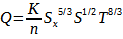 with K=0.56 (U.S.) or K=0.375 (SI),
Where
S is the longitudinal slope, ft/ft (m/m),
Sx is the cross slope, ft/ft (m/m),
T is the flow spread, ft (m),
Q is the rate of discharge, cfx (m3/S).
Expressing Q in terms of the depth of flow at the curb:
![]()
Where d=TSx is the flow depth in ft (m).
Rewriting the gutter flow Manning’s equation for spread T gives
![]()

Gutter Flow Spread – Click for source
INLET DESIGN
Inlet design refers to the planning and engineering of structures and devices that facilitate the entry of stormwater runoff into storm drainage systems while preventing sediment and debris from entering and avoiding flooding, erosion, and other negative impacts on the environment and public safety.
Sizing Grates with Slopes
Example:
Given: T = 6 ft, Sx = 0.04, S = 0.03, n = 0.016, calculate interception capacity for the grate: 2’x2′ P-1-⦺ grate. Base calculations for the condition of no spread beyond the shoulder.
Solution:
Gutter flow capacity is
![]()
Gutter flow velocity is
![]()
The ratio of frontal flow to gutter flow is
E0 = Qw = 1 – (1 = w/T)2.67.
The frontal flow interception efficiency of grates is calculated by
Rf = 1 – 0.09(V – V0).
With V0 according to table

Splash-Over Velocity of Common Inlet Grates, V0 – Click For Source
The side flow interception efficient is
![]()
Where
L is the length of grate, ft(m),
V is the gutter flow velocity, ft/s (m/s),
K = 0.15 U.S., K = 0.0828 SI,
Sx is the shoulder cross slope.
The overall efficiency is
E = RfE0 + Rs(1 – E0).
The intercepted flow of a grate is expressed as
Qi = EQ.
Slotted Inlets
The inlet capacity for the weir flow condition is
Q = Cw(L + 1.8W0)d1.5,
Where
W0 is the width of gutter depression, ft(m),
d is the depth of water at slot inlet, ft(m),
L is the length of slow, ft(m),
Cw = 2.5 (U.S.) or Cw = 1..4 (SI).
The orifice flow condition is
Q = 0.8LW(2gd)0.5,
Where
W is the width of the slow, ft(m),
g is the acceleration of gravity.
Inlet Spacing
Given Q, S, Sx, and T
(a) The flow captured by the first inlet on each shoulder is calculated by
d = TSx,
![]()
Add x% accounting for interception by the curb piece,
Ql = Ql(1 + x%).
(b) The efficiency of the inlet
E = Ql/Q.
Bypass flow is Q – Ql.
(c) The maximum spacing to the second set of inlets, accounting for the bypass flow from the first inlets
[i] First try T![]()
d = SxT.
Calculate flow interception
![]()
Add x% for side interception
Ql = Ql(1 + x%).
E = Ql/Q.
Allowable roadway runoff is
Q – Ql.
Maximum tributary area:
A = Q/Cl
The spacing to the second set of inlets is
L = A/W.
Sizing Drain Inlets of Zero-Slope Ground
The road has zero or nearly zero grade for the cases of traversing through flat lands.
With given Sx total width of lanes W, shoulder with W’, the Mannings’s coefficient n, and the intensity l, the max spacing for the inlets can be calculated with the following procedures.
The summation of the width is
∘W = W + W’
The gutter flow per unit length of roadway is
q = ∘Wl/43560.
Setting the max water surface height is
ymax = SxW’
Then, the max spacing between inlets is
![]()
DESIGN OF STORM DRAIN
Designing a storm drain involves the planning and engineering of a system of pipes and structures that convey stormwater runoff from rainfall events to receiving bodies of water, while preventing flooding, erosion, and other adverse impacts on the environment and public safety.
The peak of runoff at each inlet is calculated by the rational method:
Q = CIA.
Then, a storm water drain network could be established with the information of the pressure and flow rate at each inlets. The cross-Handy method introduced before could be used now.
INTENSITY
Firstly, the intensity of the rainfall for a certain duration of indicated frequency is determined based on the intensity-duration-frequency (IDF) curves.
To illustrate the process, we use the precipitation frequency data collected by NOAA’s National Weather Service as an example. The studied location is station Action CAMP (97-0386) in CA and the data type is the precipitation intensity. The input setup is shown in the following figure.

Illustration of the Input for Getting the Precipitation Intensity Data
Then, we can get the IDF curves as shown below.

The Intensity-duration-frequency Curve

Intensity-duration-frequency Data
For the case of a 500-yr return period with 30-min duration, by reading the plot or the table, the rainfall intensity is 2.66 in/hr. The rainfall intensity obtained from this step is used for the following peak discharge computation.
TRAVEL TIME AND TIME OF CONCENTRATION
To determine the duration for reading the rainfall intensity, we introduce the concept of time of concentration and travel time. The time of concentration is used as the duration for reading the rainfall intensity at the end. The definitions of time of concentration are:
- Time to equilibrium of the catchment under a steady rainfall excess;
- The time between the center of mass of rainfall excess and the inflection point on the recession of the direct runoff hydrograph;
- Travel time of a wave to move from the hydraulically most distant point in the catchment to the outlet;
- Travel time required for a particle of water to flow hydraulically from the most distant point in the watershed to the outlet or design point.
In the velocity method, the travel time is calculated by
Tt = L/60V’
Where
Tt is the travel time,
L is the length of flow,
V is the velocity
Then, the time of concentration is the sum of the travel times such that
![]()
Where
Tc is the time of concentration.
Notice that for the principal flow path to consist of segments with different slope, land cover, and flow behavior, it must be divided in segments.
The overland sheet flow is considered as the surface flow for calculating the travel time. The flow velocities is estimated by using a reduced Manning’s equation for given Mannings’s and hydraulic radius such that
V = kS0.5,
with
k = 1.486Rh⦝/n,
Where
V is the flow velocity,
k is a coefficient in the simplified Manning’s equation,
Rh is the hydraulic radius,
N is the Mannings’s roughness coefficient for the overland sheet flow.
Notice that the Manning’s roughness coefficient used for the overland sheet flow is not the same as for the open channel flow. The coefficient can be read from the following tables:

Manning’s Roughness Coefficient for Overland Flow Surfaces

Coefficients for Estimating Travel Time in Sheet Flow Using Manning’s Simplified Equation
Or we can read the velocity based on the surface type and slope from the following table directly.

Velocities for the Upland Method of Estimating Travel Time
PEAK DISCHARGE COMPUTATION
The rational method is the most widely used method for estimation of the rainfall peak discharge. The rational method is usually limited to areas below 1 sq mile (640 acres). The rational method is a formula such as
Qp = CIAc
where
Qp is the discharge, cfs,
C is the runoff coefficient, dimensionless,
I is the rainfall intensity corresponding to a duration equal to the time of concentration (in/hr) and for a design frequency, in./h,
Ac is the catchment area, ac.
The runoff coefficient for different types of area are shown in the following tables.

Runoff Coefficient for the Rational Method Part 1

Runoff Coefficient for the Rational Method Part 2
Applying the rational method on non-homogeneous areas, a weighted runoff coefficient should be computed, such that
![]()
where
Cw is the weighted runoff coefficient,
Cj is the runoff coefficient for area j,
A is the area for land cover j,
n is the number of land covers within the watershed
The equation for the discharge becomes
![]()
Generally, we face a non-homogeneous system with multiple inlets and pipe systems. The rational method is used to compute the peak discharge for each inlet.
A drainage system for the half main roadway of the earthbag village with multiple inlets and several catchment sections is used to illustrate the procedures of using the rational method to estimate the peak discharges.

One Drainage System With 5 Inlets and 6 Catchment Sections of the Earthbag Village
1) Determining the area A, the type of surface C, and the time of concentration of each section.
The catchment area of each section can be obtained from measurements of engineering drawings.
For simplicity, the brick pavement street is assumed as the surface type for all sections. So that the runoff coefficient is C = 0.85.
The time of concentration is only calculated for section 1 as an example. For a paved surface, the coefficient for estimating the travel time k = 20.8. Then, assuming a S = 0.01 slope, the the flow velocity is
V = kS0.5 = 20.8(0.01)0.5 = 2.8 ft/s.
With knowing the length from the most distant point to the inlet of section 1 L =102 fy by reading the engineering drawings as shown in the following figure. The time of concentration is equal to the travel time as there is only one segment for section 1 such that
Tc = Tt = L/V = 102/2.8 = 36 sec = 0.6 min.
As the minimum duration of the IDF curve is 5 min., the calculated time of concentration is less that it. So Tc = 5 min is used as the time of concentration of section 1. For simplicity, the time of concentration of all sections is Tc = 5 min. The rainfall intensity of time of concentration Tc = 5 min for 500-yr return period is I1 = 6.56 in/hr.
Information of all section can be presented within a table such that:

Area and the Time of Concentration of Each Section – Click for source

The Length From the Most Distance to the Inlet 1 of Section 1 for Calculating the Travel Time
2) Compute the peak discharge at inlet 1
Q1 = C1I1A1 = 0.85(6.56)(0.05838) = 0.3255 cfs.

Inlet 1 Peak Discharge – Click for source
3) Pipes length, slope and flow velocities of pipe 1
Determining the pipe’s dimension based on the peak flow calculated previously and storm pipe sizing table shown below. Pipe size 6 inch is used. Considering the full pipe flow, the pipe velocity is calculated for determining the travel time.

Storm Pipe Sizing

Pipe 1 Flow Velocity and Travel Time – Click for source
4) Peak discharge at inlet 2
In this case, there are two times of concentration arriving at inlet 2.
a) 0.6 min from Section #1 + 0.04625 travel time inside Pipe #1=0.64625 min.
b) 0.6 min time of concentration from Section 2.
Choose the longest time:

Inlet 2 Possible Time of Concentration T_c – Click for source
The rainfall intensity corresponding to the T_c=0.64625 min can not be read from the table directly, we use T_c =5 min as time of concentration and the corresponding rainfall intensity is I=6.56 in/hr.
Use total area: Area_1+Area_2. Then, we can get the peak discharge at inlet 2:

Inlet 2 Peak Discharge – Click for source
Based on the peak flow rate, selected pipe slope, pipe material, and the drain pipe sizing table, we get flow velocity and travel velocity in pipe such that:

Pipe 2 Flow Velocity and Travel Time – Click for source
1) Peak discharge at inlet 3
In this case, there are three possible times of concentration arrive at inlet 3.
Choose the longest time and find the rainfall intensity:

Inlet 3 Possible Time of Concentration T_c – Click for source
The peak discharge is:

Inlet 3 Peak Discharge – Click for source
Based on the peak flow rate, selected pipe slope, pipe material, and the drain pipe sizing table, we get flow velocity and travel velocity in pipe such that (the result table is same as pipe2):

Pipe 3 Flow Velocity and Travel Time – Click for source
2) Peak discharge at inlet 4
In this case, there are four possible times of concentration to arrive at inlet 4.
Choose the longest time and find the rainfall intensity:

Inlet 4 Possible Time of Concentration T_c – Click for source
The peak discharge is:

Inlet 4 Peak Discharge – Click for source
Based on the peak flow rate, selected pipe slope, pipe material, and the drain pipe sizing table, we get flow velocity and travel velocity in pipe such that the velocity (26.1904 ft/s) is faster than pipe3′ (21.6197 ft/s):

Pipe 4 Flow Velocity and Travel Time – Click for source
3) Peak discharge at inlet 5
Choose the longest time and find the rainfall intensity:

Inlet 5 Possible Time of Concentration T_c – Click for source
The peak discharge is:

Inlet 5 Peak Discharge – Click for source
From the previous calculation of the peak flow rate for each catchment area, we can find that even the longest time of concentrations is much less than the minimum measuring duration 5 minutes because of relatively small catchment areas. For simplicity, we can use the minutes as time of concentration for every catchment area to estimate rainfall intensities.

A Schematic Diagram Of The Drain Of The Stormwater Harvesting Of The Earthbag Village. The Diagram Shows The Sections, Locations Of Drain Inlets, Layout Of Drainage Plumbing, And Direction Of Drain Flow. S-Section, I-Inlet.

Overflow Pipes From Barrels to the Larger Water Tank Under the Shower Room

Overflow Pipes From Barrels to the Larger Water Tank Under the Shower Room

Sedimentation Chamber for Stormwater Harvested From the Main Roadway Drain

Peak Flow Downstream of the Inlet of the Drain – Click for source

Peak Flow Downstream of the Inlet of the Drain – Click for source
AQUAPINI & WALIPINI WATER CATCHMENT
 Water collection (with storage in the central pond) is planned for the Aquapinis, Walipinis, and surrounding roadways. Water catchment for this area has been calculated using the following color coordinated zones: Pink for small structures, Orange for the large structures, and Blue for Roads & Walkways.

Food Infrastructure Water Collection Zones: Click to Visit the Aquapini and Walipini Open Source Hub
WATER CATCHMENT OFF THE SMALL STRUCTURES (PINK)
The water collection area of each small structure (pink) equals 2079 square feet x 4 structures = 8,316 sq. ft. Using a (conservative for our location) 10-inch annual rainfall* and applying the formula for calculating water harvesting (catchment area x rainfall x runoff) yields: (8,316) X (.833) X (7.48) = 51,885 gallons of water harvested per year from these structures.
WATER CATCHMENT OFF THE LARGE STRUCTURES (ORANGE)
The water collection area of each large structure (orange) equals 3,399 square feet x 2 structures = 6,798 sq. ft. Using a (conservative for our location) 10-inch annual rainfall* and applying the formula for calculating water harvesting (catchment area x rainfall x runoff) yields: (6,798) X (.833) X (7.48) = 42,357 gallons of water harvested per year from these structures.
WATER CATCHMENT OFF THE ROADWAYS AND WALKWAYS (BLUE)
- Central circle = 5,541 sq. ft.
- Walkways = 1,250 sq. ft.
The water collection area of the walkways and central area equals 6,791 sq. ft. Using a (conservative for our location) 10-inch annual rainfall* and applying the formula for calculating water harvesting (catchment area x rainfall x runoff) yields: (6,791) X (.833) X (7.48) = 42,313 gallons of water harvested per year from this area.
TOTAL WATER CATCHMENT FOR OUR INITIAL FOOD INFRASTRUCTURE:
136,555 GALLONS OF WATER
*Note: For calculating cistern and pond sizes we used the average annual rainfall for our location of 13.6 ~ 15 in = average of 368.3 mm. For calculating pipe size we used the Daily Critical Rainfall (the maximum daily amount of rainfall in our location) of 1.3″ / 33 mm.
DUPLICABLE CITY CENTER WATER COLLECTION
![]() Water will also be collected off the entire Duplicable City Center Hub. Water catchment for this area has been calculated using the following color coordinated zones: Pink for the domes and Blue for the central area. There is a 4th floor cupola that will cover the central area but water will still be collected from this cupola so we have used the zones you see below for simplicity.
Water will also be collected off the entire Duplicable City Center Hub. Water catchment for this area has been calculated using the following color coordinated zones: Pink for the domes and Blue for the central area. There is a 4th floor cupola that will cover the central area but water will still be collected from this cupola so we have used the zones you see below for simplicity.

Duplicable City Center Water Catchment Zones – Click for the Details Page
The Duplicable City Center footprint for each of the domes (area of the circle) was calculated for rainwater catchment. The area of a 74′ diameter circle equals 4,300 feet x 3 domes = 12,900 sq ft. Using a (conservative for our location) 10-inch annual rainfall* and applying the formula for calculating water harvesting (catchment area x rainfall x runoff) yields: (12,900) X (.833) X (7.48) = 80,485 gallons of water harvested per year from the domes.
* Note: For those interested, the actual surface area of each of the Duplicable City Center’s 74′ diameter/35′ high domes (pink) can be quickly calculated using this tool as equalling 8,149 feet.
WATER CATCHMENT FROM THE CUPOLA AND CENTRAL AREA (BLUE)
The area of the central water collection zone (blue) for the Duplicable City Center includes the area shown on the map above (topped with the cupola that will cover much of this area) equaling roughly 3,010 sq ft. of rain collecting space. Using a (conservative for our location) 10-inch annual rainfall* and applying the formula for calculating water harvesting (catchment area x rainfall x runoff) yields: (3,010) X (.833) X (7.48) = 18,754 gallons of water harvested per year from the Duplicable City Center Hub.
TOTAL WATER CATCHMENT FOR THE DUPLICABLE CITY CENTER
18,754 GALLONS OF WATER
*Note: For calculating cistern and pond sizes we used the average annual rainfall for our location of 13.6 ~ 15 in = average of 368.3 mm. For calculating pipe size we used the Daily Critical Rainfall (the maximum daily amount of rainfall in our location) of 1.3″ / 33 mm.
SOLAR ARRAY WATER COLLECTION
Water will also be collected off of and under our energy infrastructure of solar panels that will cover a total of 7,392 square feet. Using a (conservative for our location) 10-inch annual rainfall* and applying the formula for calculating water harvesting (catchment area x rainfall x runoff) yields: (7,392) X (.833) X (7.48) = 46,058 gallons of water harvested per year.
TOTAL WATER CATCHMENT FOR THE SOLAR ARRAY:
46,058 GALLONS OF WATER
*Note: For calculating cistern and pond sizes we used the average annual rainfall for our location of 13.6 ~ 15 in = average of 368.3 mm. For calculating pipe size we used the Daily Critical Rainfall (the maximum daily amount of rainfall in our location) of 1.3″ / 33 mm.
SWALE CREATION AND BENEFITS
Swale creation is part of the One Community water conservation plan, stewardship strategy, and food forest design. In addition to water collection off all the structures of One Community, we will also open source project-launch blueprint the effectiveness and value of swale creation for land restoration, food forest establishment and support, and greywater processing.

Tamera Eco-Settlement Water Conservation Results: This Took Less Than 4 years
WHAT IS A SWALE
A swale is a ditch and berm system designed to halt overland water flow and maximize water infiltration. The design calls for an excavated ditch along the contour lines of a property such that the ditch is always following the level contour of the land. The soil excavated from the ditch is moved to the downslope side to form a berm. It is important to make sure that the top of the berm is level, in order to prevent accumulated water in the swale from finding a low spot and washing out the berm. The entire area is raked smooth, mulched, and densely planted with a broad mix of annual and perennial species. In dry climates it may be necessary to irrigate the plantings until the first rain event, or until the plantings take hold.
WHAT DOES A SWALE DO
A properly designed and constructed swale accomplishes a number of important functions. First and foremost is the retention in the landscape of the maximum amount of precipitation or inflow. As the infiltrated water moves down and out through the soil profile, it enables the growth of trees and other plants upslope and downslope of the swales that would not otherwise survive on the site. The tree cover in turn shades and mulches the swale, maintaining and enhancing the infiltration; as the trees grow, their roots help guide moisture ever deeper into the soil profile. This synergistic feedback loop makes possible the reforestation or afforestation of even the driest regions. The system is expanded with additional swales upslope and downslope across the landscape.
It is important to understand that a swale is NOT meant to direct or divert the flow of water across the slope. Rather, the design and intention of a swale is to HALT the flow of water, so that it collects in the swale and has the chance to sink into the soil. In areas that receive sufficient rainfall, swales can be connected to a series of deeper ponds or impoundments to hold larger amounts of water. These can be constructed to increase the area of infiltration, or designed as permanent ponds.
Understanding the soil structure where a swale is under consideration is important to achieve the aim of maximum infiltration. On most soils, the mulch layer starts the generation of the soils microbiota, which improves the crumb structure and drainage of the soil. In the case of clay, treatment with gypsum (calcium sulfate) followed by mulch, will help the clay flocculate and achieve percolation. In extremely rocky or shale situations, mechanically ripping the bottom of the swale with a dozer shank may be necessary.
As a swale establishes its associated habitat, an accelerated turnover in species composition is seen. The initial annuals and short-lived perennials are soon shaded out by taller, longer-lived trees and shrubs, which in turn are succeeded by slower growing climax forest species. At each stage of this evolution, niches are created for new species, and “edge” increases at the peripheries. Properly managed, each of these niches is an opportunity for developing an ever-widening array of yields.
As the systems of multiple swales extend towards each other, the management of the interswale zone can be maintained as e.g. open meadow, agricultural field, home or village site, etc. Allowing these sites to be surrounded with swale-derived agroforest increases their soil moisture, reduces wind and evapo-transpiration, provides convenient access to wild foods, medicinal plants, and other forest yields. This approach brings Zones 3 and 4 closer to Zones 1 and 2.
A VIDEO ABOUT WHAT IS POSSIBLE AND THE ABOVE PICTURE

WATER RETENTION BENEFITS
- Erosion control
- More availability of water for agricultural use & drinking
- Slows the flow of water downstream which reduces flood risk
- Healthy soil and fresh water are the foundations of any land based ecosystem
WATER RETENTION TECHNIQUES
- Swales
- Keyline design
- Lakes & ponds
- Roof harvesting
SWALES SIMPLIFIED
Forming swales looks like this:

A swale on contour catches large volumes of water and allows it to soak into the land like this:

Water caught by a swale absorbs into the land like this:

KEYLINE DESIGN SIMPLIFIED
Ripping plow lines on contour, pushes rushing water from the valleys out to the ridges like this:

PONDS AND LAKES SIMPLIFIED
Excess water from swales is directed to ponds and lakes like this:
A SPECIAL NOTE ABOUT BAMBOO
Bamboos are an especially useful set of plants for swales. Monopodial (“clumping”) bamboos have very dense root systems, and excel as silt traps. The sympodial or so-called “running” bamboos spread out and form groves of canes that can quickly shade and mulch large areas. Their root systems will seek moisture, and they can spread along a swale for hundreds of feet, mulching and protecting the newly installed swale as they go. Near dwellings or settlements, all greywater can be directed to bamboo groves, which will greedily filter out nitrates and nitrites. There are different species of bamboo that will grow from the equator to the arctic latitudes, and given the wide variety of yields – edible shoots, medicine, craft and construction wood, mulch, fuel, livestock browse, etc. – their judicious selection and placement should be part of any site development.
RESOURCES
- Amazon Link – “Urban Storm Water Management” by Hormoz Pazwash
- Arcicle: “URBAN DRAINAGE DESIGN: Part 1” by Dr. Walter F. Silva-Araya
- Article: “URBAN DRAINAGE DESIGN: Part 2” by Dr. Walter F. Silva-Araya
- Article: NOAA’s National Weather Service – Atlas 14 Point Precipitation Frequency Estimates: CA
- Article: One Community’s Duplicable City Center Water Catchment – Maximum Water Volume Details
- Article: J.R. HOE – Manhole Covers
- Article: Atlantis Flo-Tank® – Efficient rainwater management
- Article: “Runoff Coefficient in InfoSewer and InfoSWMM”
- Article: 2018 International Plumbing Code – Chapter 11: Storm Drainage
- Article: Krest Engineers – Manning’s n (Roughness Coefficient) for HEC-RAS 2D Modeling
- Article: Bentley StormCAD CONNECT Edition Help: I-D-F Curves
- Article: Runoff Coefficient (C) Fact Sheet – The Clean Water Team Guidance Compendium for Watershed Monitoring and Assessment
- Article:Belding Tank Technologies – How Long Do FRP Tanks Last?
- Article: Atlantis Water Tanks – Total Water Management
- Article: Bega Concrete Tanks – How Long Do Concrete Water Tanks Last Ideally?
- Article: Permaculture Research Institute – Ferro-cement Water Tanks an Affordable DIY Solution
- Article: “Preparing Rainwater for Potable Use” by Mary Ann Capehart, Janick F. Artiola Ph.D., and Susanna Eden Ph.D.
- Home Depot: Amerimax Home Products – 5 in. x 16 ft. White Aluminum K-Style Gutter
- Home Depot: Amerimax Home Products – 5 in. x 10 ft. High Gloss 80 Degree White Aluminum Half Round Gutter
- Article: “Rainwater Harvesting” by Alex Wilson
- Article: Danner Manufacturing – Proline High-Flow Submersible Water Pumps
- Article: Lowe’s: A.O. Smith 52-Gallon Vertical Pressure Tank
- Article: H2O Equipment – Waterlogged Pressure Tank Definition
- Article: Rainwater Harvesting: System Planning – Ch 10. “Roofing, Gutters, and Downspouts” by Justin Mechell et al.
- Article: “Rainwater Harvesting and Make Up Water: The Why, When, and How” by Dave Adams
- Product Description: Water Storage Tank – 1000 Gallon Norwesco Plastic Potable Water Storage Tank | Specs
- Article: Schedule 40 PVC Pipe – Charlotte Pipe 3-in x 10-ft 260 Psi Schedule 40 PVC Pipe
- Product Description: Ball Valve – Matco-Norca 770N PVC Ball Valve | Specs
- Article: 3″ Schedule 40 PVC Tee – Schedule 40 PVC Tee – Socket x Socket x Socket (401-030)
- Article: 3″ Schedule 40 PVC Cross – Schedule 40 (S x S x S x S) PVC Cross 420-030
- Article: 2 in. Spigot X 3/4 in. Reducing Bushing – Charlotte Pipe Schedule 40 2 in. Spigot X 3/4 in. D FPT PVC Reducing Bushing
- Article: PVC Spigot Kit – Voaesdk PVC Spigot Kit Rain Barrel Faucet Kit 3/4 inch Rain Barrel Valve with Bulkhead Fitting Adapter
- Article; PVC Flexible Coupling – Fernco 3 in. x 3 in. PVC DWV Mechanical Flexible Coupling
- Product Description: 3″ PVC Bulkhead Fitting – 3″ Hayward BFAS Series PVC Bulkhead Fitting W/Socket X Threaded Ends | Specs
- Product Description: Male Adapter Schedule 40 – Male Adapter: Schedule 40, 3 in x 3 in Fitting Pipe Size, Male Spigot x Male NPT, White | Specs
- Product Description: Male Spigot Schedule 40 – Male Adapter: 2 in x 2 in Fitting Pipe Size, Schedule 40, Male Spigot x Male NPT, Black | Specs
- Article: Return Bend PVC Pipe – Charlotte Pipe 3-in PVC DWV Return Bend
- Article: Street Elbow Schedule 40 – Spears 3″ PVC Sch. 40 90° Street Elbow (MIPTxSOC)
- Article: Screen Vent – 3″ Round Open Screen Vent – Mill – Package of 4
- Article: Downspout Filter – Rain Harvesting Pty Leaf Eater Ultra Downspout Filter | Specs
- Article: Advanced Downspout Filter – Rain Harvesting Pty Leaf Eater Advanced Downspout Filter (Round Output) – Assembly Instructions | Specs
- Article: Gutter Guard – A-M Gutter Guard – Aluminum 6″ (23 Feet, Mill Finish)
- Article: Water Storage Tank Specs Drawing – 1600 GALLON VERTICAL TANK, SHORT
- Article: Alkaline and UV System – Article: NU Aqua Platinum Series 7 Stage Alkaline and UV Ultraviolet 100GPD RO System with Booster Pump
- Article: Well Water UV Filtration System – Rhino® Well Water with UV
- Article: High Flow Water Filtration System – Everpure EV9328-06 High Flow CSR Triple-MC2 Water Filtration System with Pre-Filter – .5 Micron and 5 GPM
- Article: Single Membrane Water Maker – Watermaker: AC 110-220V, 970W, 20 GPH, Single Membrane.
- Article: Water Filter System – 3M Water Filter System: 0.2 micron, 15 gpm, 162,000 gal, 3/4 in, NPT, 24 1/8 in Overall Ht
- Article: Water Pump – FLOJET Booster Pump System: Self-Priming, 3/4 in Barbed, 3/4 in Intake Connection Size, Barbed, 2840
- Article: The Rain Catcher: Cisterns for Rainwater Storage ” Above & Below Ground
- Article: “Cistern Design Considerations for Large Rainwater Harvesting Systems” by Greg Kowalsky, BSME, and Kathryn Thomason, P.E.
- Article: National Sanitation Foundation home page
- Product description: Rainwater Integrated Filtration Unit – IHS22-E4 Integrated Filtration Unit | Specs
- Article: Solar Water Distillation Fact Sheet – Safe Drinking Water Foundation
- Article: Caltrans – Erosion Control Toolbar: Permeable Paving
- Article: Home Depot: U.S. TRENCH DRAIN – 18 in. Storm Water Pit and Catch Basin for Modular Trench and Channel Drain Systems with Galvanized Steel Grate
- Article: Houston Landscape Pros: Catch Basin Drain Installation
- Article: US Environmental Protection Agency: Learn About Green Streets
- Article: Minneapolis Street Design Guide: 3.3E Green Stormwater Infrastructure
- Article: InfoDrainage 2021.3 Help Documentation: Swale
- Article: JC Property Professionals: Should you install a French drain?
- Article: Property Pros: Rain Gardens
- Article: Amazon: U-nitt Rain Chains, Roof Gutter Downspout/Spout Channel, Rainwater Water Catcher/Diverter, 8.5 feet Length, Metal, Gray, Hand Painted Basketball, Sports Theme, Square Cup, 8801AL
- Article: Summit…responsible solutions 110-12 Mosquito Dunks, 6-Pack, Natural, 6 pack
- Article: US Environmental Protection Agency: Water Reuse Research
- Article: “Wastewater Treatment and Recycling” by Caroline Gleason
- Science Direct article: Drinking Water Treatment
- Article: Atlantis Tank System ” Underground Stormwater Retention & Infiltration System
- Article: Atlantis Rainwater Harvesting Tank System – Underground Rainwater Tank
- Article: Grass Reinforcement Structure for Landscaping by Atlantis
- Article: US Fabrics: Filter Fabrics
- Article: Southern Tank & Manufacturing: Steel Water Tanks
- Article: Pioneer Water Tanks: Model XLE 15/02 with 20,243-Gallons Capacity
- Article: Urban Storm Water Management, 2nd Edition – Hormoz Pazwash
- Article: Urban Drainage Design Part 1 – Dr. Walter F. Silva-Araya
- Article: Urban Drainage Design Part 2 – Dr. Walter F. Silva-Araya
- Article: National Oceanic and Atmospheric Administration – Precipitation Frequency Data Server (PFDS)
- Article: One Community: Duplicable City Center Water Catchment
- Article: Green Infrastructure Right-of-Way Inlet Type Selection: Hydraulic and Siting Factors to Consider to Optimize Design
SUMMARY
![]() The benefits of harvesting rainwater are many. With minimal filtration it can be used for bathing, clothes washing, and dish washing. With no filtration it can be used for watering gardens and houseplants, flushing toilets, washing cars and buildings, composting, outdoor ponds and water features, fire control, etc. Collecting and using rainwater reduces municipal water needs and peak demands (demands on groundwater), reduces costs/water bills, and is good for the environment. We are open sourcing the rainwater catchment specifics for all seven different village models, the Duplicable City Center Hub, and our sustainable food systems to help with open source collaborative improvement of the designs, as an example of the process and needs for other similar-sized structures, and to share here additional specifics like purchasing and installation details, the maintenance and upkeep process, etc.
The benefits of harvesting rainwater are many. With minimal filtration it can be used for bathing, clothes washing, and dish washing. With no filtration it can be used for watering gardens and houseplants, flushing toilets, washing cars and buildings, composting, outdoor ponds and water features, fire control, etc. Collecting and using rainwater reduces municipal water needs and peak demands (demands on groundwater), reduces costs/water bills, and is good for the environment. We are open sourcing the rainwater catchment specifics for all seven different village models, the Duplicable City Center Hub, and our sustainable food systems to help with open source collaborative improvement of the designs, as an example of the process and needs for other similar-sized structures, and to share here additional specifics like purchasing and installation details, the maintenance and upkeep process, etc.
FREQUENTLY ANSWERED QUESTIONS
Use this page (click here) if you have a question you’d like answered.
![]()